1
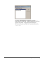
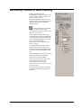
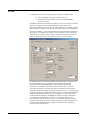
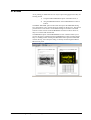
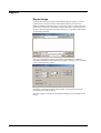
User's Guide
AIDA Image Analyzer
Multi Labeling
raytest Isotopenmeßgeräte GmbH
AIDA Image Analyzer
Multi Labeling User’s Guide
The software described in this manual is furnished under a license agreement and
may be used only in accordance with the terms of the agreement.
Copyright Notice
Copyright (c) 2001 raytest Isotopenmeßgeräte GmbH
All Rights Reserved
This document may not, in whole or in part, be copied, photocopied, reproduced,
translated, or reduced to any electronic medium or machine-readable form
without prior consent in writing from raytest Isotopenmeßgeräte GmbH,
Benzstr. 4, 75334 Straubenhardt, Germany.
Trademarks
AIDA Image Analyzer, AIDA Array Metrix, AIDA Annotation, AIDA 1D Multi
Labeling, AIDA 1D Evaluation, AIDA 1D Densitometry, AIDA 2D Multi
Labeling, AIDA 2D Densitometry, AIDA Easy Array, AIDA Whole Body
Autoradiography, AIDA 1D Thin Layer Chromatography, AIDA 2D Thin Layer
Chromatography are trademarks of raytest Isotopenmeßgeräte GmbH.
Other product names mentioned in this manual may be trademarks or registered
trademarks of their respective companies and are the sole property of their
respective manufacturers.
2001 05 1.0
Table of Contents
Introduction
3
Starting Multi Labeling............................................................................................................. 3
User Interface of Multi Labeling
5
Data Windows in Multi Labeling ............................................................................................. 5
Multi Channel Image Window .................................................................................. 5
Multi Channel Control Toolbox ............................................................................................... 6
Publishing Toolbox in Multi Labeling ..................................................................................... 9
Print.......................................................................................................................................... 10
Preview .................................................................................................................................... 11
Export ...................................................................................................................................... 12
Export Image ............................................................................................................ 12
Performing Multi Labeling Evaluations
13
Performing 1D Multi Labeling Evaluations........................................................................... 13
Performing 2D Multi Labeling Evaluations........................................................................... 15
Introduction
Starting Multi Labeling
The AIDA MULTI LABELING modules allow you to evaluate one image (the
master image) by comparing it with one or two other images, and to easily
visualize the result of the comparison. For this purpose, the images can be
displayed in lookup table colors (red, green, or blue) instead of grayscales,
superimposed on each other. The combined colors resulting from this additive
color synthesis indicate relative signal strength. For example, you can combine
the scans of up to three different fluorescent dyes into a single image, or you can
compare re-probed blots by using the same label.
AIDA MULTI LABELING is actually an add-on for the 1D EVALUATION and
2D DENSITOMETRY module respectively, supplementing MULTI CHANNEL
DISPLAY functionality. Therefore, 1D MULTI LABELING represents the
MULTI CHANNEL DISPLAY extended version of 1D EVALUATION,
whereas 2D MULTI LABELING can be described as the MULTI CHANNEL
DISPLAY extended version of 2D DENSITOMETRY.
Using 1D MULTI LABELING, you can transfer the runlength calibration (for
MW, IF etc.) from one (calibration) image to the master image.
2D MULTI LABELING allows you to normalize one master image using a
second one.
The core component of the MULTI LABELING add-on is constituted by the
MULTI CHANNEL DISPLAY function, responsible for visualizing the image
comparison in 1D MULTI LABELING and 2D MULTI LABELING.
Depending on the desired evaluation, select the appropriate evaluation mode
(1D MULTI LABELING, 2D MULTI LABELING) by clicking the
EVALUATION button in the toolbar. A dialog box appears offering you a list of
available evaluation modes. The list entries reflect the installed AIDA
application modules. Select the appropriate list item und click OK. Note that
these evaluation modes are only available if you purchased the AIDA MULTI
LABELING option.
4 • Introduction
User's Guide AIDA Image Analyzer Multi Labeling
User Interface of Multi Labeling
Data Windows in Multi Labeling
In addition to the AIDA standard data windows IMAGE and HISTOGRAM and
the additional data windows specific to the respective core module, the following
data window is available in the MULTI LABELING mode:
•
MULTI CHANNEL IMAGE
You can access this data window by selecting the MULTI CHANNEL IMAGE
entry from the VIEW menu.
Multi Channel Image Window
In the MULTI CHANNEL IMAGE window the overlaid images are displayed.
After selecting a master image and one or two reference images using the
controls of the MULTI CHANNEL CONTROL toolbox (see below), you can
adjust the position of these images to yield maximum superimposition.
Multi Channel Control Toolbox
In addition to the standard AIDA toolboxes DISPLAY CONTROL and
PUBLISHING LAYOUT and the core evaluation module-specific toolboxes, the
MULTI CHANNEL CONTROL toolbox becomes available after selecting the
appropriate MULTI LABELING evaluation mode. You can access these
additional toolboxes from the EVALUATION menu or by clicking the
appropriate button on the toolbar.
The controls of the MULTI CHANNEL
CONTROL toolbox allow you to add
images to the master image, to move them
against each other and to adjust the
contrast of the images in the MULTI
CHANNEL IMAGE window.
To display the MULTI CHANNEL
CONTROL toolbox:
On the main menu, click EVALUATION,
and then click MULTI CHANNEL
CONTROL. Alternatively you can select
the MULTI CHANNEL CONTROL button
on the toolbar.
Clicking the SELECT… button opens the
EDIT CHANNELS dialog box, which is
used to select a reference image to be
added to or removed from the MULTI
CHANNEL IMAGE window as well as the
colors for both images:
To select a image for the reference channel
(called STANDARD CHANNEL or
NORMALIZATION CHANNEL,
depending on the active MULTI
LABELING mode), click the BROWSE…
button. The OPEN FILE dialog box
appears, prompting you to choose a file.
You can select pure images (like TIFF or
BMP files) or AIDA Evaluation files
(.adf). Since each ADF file is associated to
exactly one image, by selecting an ADF
file, you actually select the image
associated with.
To remove an image from the reference channel, just delete its name in the
combo box.
Note that in 2D MULTI LABELING the image of the second channel
automatically becomes the normalizing image.
6 • User Interface of Multi Labeling
User's Guide AIDA Image Analyzer Multi Labeling
In 1D MULTI LABELING, you will be asked whether the runlength calibration
should be taken over from the added channel to the master image. Of course the
runlength calibration can only be taken over from the added channel, if you have
made a runlength calibration on that image at all.
Use the MOVE… button to move and/or rotate the images against each other. If
you click the button, the top section of the MULTI CHANNEL CONTROL
toolbox is changed, providing controls for moving, flipping and rotating.
From the MOVE drop-down list select the
image you want to move, flip or rotate.
Then drag it with the mouse pointer to the
desired position in the MULTI CHANNEL
IMAGE window. You may also use the
arrow keys on your keyboard to move the
image by pixel. Alternatively you can enter
the shift values for x- and/or y-direction in
the appropriate combo boxes below the
MOVE drop-down list.
Use the first two of the four buttons to horizontally and
vertically flip the image, and the remaining two to rotate the image by 90
degrees counterclockwise and clockwise respectively (no pixel interpolation
necessary!).
Accomplish the move action by clicking the OK button on the MOVE panel
(unless you confirm the action, no previously computed value will be changed).
You can use the VIEW button to open the MULTI CHANNEL IMAGE window
for displaying the overlaid images.
User's Guide AIDA Image Analyzer Multi Labeling
Multi Channel Control Toolbox • 7
If you want to switch a channel temporally
off, so that this channel is no longer shown
in the MULTI CHANNEL IMAGE
window, select the appropriate colored
check box next to the file path indicating
the channel's image. Enabling or disabling
a channel does not change any computed
values.
Transfer Curve Section
The controls of TRANSFER CURVE
section are used to adjust the contrast of
the images in the MULTI CHANNEL
IMAGE window. Select the channel, to
which the controls should be applied by
selecting the appropriate colored button
above the histogram window. The
histogram window and its controls below
are similar to those of the DISPLAY
CONTROL toolbox, described in the
AIDA Image Analyzer Basic Concepts and
Features User's Guide.
8 • User Interface of Multi Labeling
User's Guide AIDA Image Analyzer Multi Labeling
Publishing Toolbox in Multi Labeling
In MULTI LABELING the
PUBLISHING LAYOUT toolbox of the
respective core evaluation module (1D
EVALUATION or 2D
DENSITOMETRY) is expanded by an
additional button for specifying the print
options for the MULTI CHANNEL
IMAGE window:
Selecting the MULTI CHANNEL
option, you can specify the paper
orientation for the printout as well as the
items you want to print.
In the FORMAT part select the paper
orientation for the printout (PORTRAIT
or LANDSCAPE). The size of the image
can be automatically adjusted to fit the
page (AUTOMATIC SIZE).
Alternatively you can enter the zoom
factor in percent.
The PARAMETER checkbox of the
PRINT controls section enables the
printing of the data and comment which
are found in the FILE INFORMATION
box.
Check WHITE BG, if you want to set the
background color for the printout to
white instead of black (default).
Selecting COLORSCALE prints a bar
next to the image, showing the
representation of various signal
intensities as color scale in the way it was
set for the image.
SCALES prints a bar next to the image
that shows the length representation in
the image.
User's Guide AIDA Image Analyzer Multi Labeling
Publishing Toolbox in Multi Labeling • 9
Print
In AIDA there are two ways for printing your image and evaluation data:
1) Select the PRINT option from the FILE menu, or
2) use the PROTOCOL PRINT section on the PUBLISHING
LAYOUT toolbox.
The PRINT command of the FILE menu allows you to print your data 'on the fly'
without permanently storing the layout/printing settings, whereas the
PROTOCOL PRINT panel provides you with a complete set of printing features
which includes saving the setting with the data file for reasons of reproducibility.
Selecting the PRINT... option from the FILE menu opens the PRINT dialog box,
allowing you to configure the printout to contain only the overlays, results and
graphs that are currently needed. Click the check boxes for the various items to
enable or disable them. Select the number of copies, you want to print.
In addition to the PARAMETER and IMAGE standard AIDA checkboxes and
the checkboxes specific to the respective core evaluation module, the
MULTICHANNEL PARAMETER and MULTICHANNEL IMAGE
checkboxes are available in the left part of the PRINT toolbox. Select the
appropriate checkboxes to include the respective information in the printout.
The MULTICHANNEL PRINT OPTIONS section allows you to set the printing
options for the MULTI CHANNEL IMAGE printout. As for the PARAMETER
AND IMAGE OPTIONS section, you can configure the content range of the
printout (WHOLE IMAGE or WINDOW CONTENT), the paper orientation
(LANDSCAPE or PORTRAIT), and the size of the image representation
(AUTOMATIC SIZE or relative size in %). Use the three check boxes on the
right part of the section to enable or disable the printing of the COLORSCALE,
SCALES and WHITE BG (see the respective description in the Publishing
Layout Toolbox section above).
10 • User Interface of Multi Labeling
User's Guide AIDA Image Analyzer Multi Labeling
Preview
As for printing, in AIDA there are two ways of previewing pages before they are
actually printed:
1) Using the PRINT PREVIEW option of the FILE menu, or
2) using the PREVIEW button on the PUBLISHING LAYOUT
toolbox.
The PRINT PREVIEW option of the FILE menu opens the PREVIEW dialog
box, which allows you to specify the layout settings for the preview. The options
presented here are the same as in the PRINT dialog box and those selectable
from the various sections of the PUBLISHING LAYOUT toolbox. However,
they are not stored with the data file.
The PREVIEW option of the PUBLISHING LAYOUT toolbox allows you to
preview all pages as configured in the PUBLISHING LAYOUT toolbox before
they are actually printed. Clicking the PREVIEW button opens the PREVIEW
window directly, since all layout setting are already made through the PRINT
PROTOCOL panel.
User's Guide AIDA Image Analyzer Multi Labeling
Preview • 11
Export
Export Image
To export the content of the MULTI CHANNEL IMAGE window in a raster
graphic format, choose the MULTI CHANNEL IMAGE option from the
EXPORT submenu of the FILE menu or select the COPY CONTENT from the
EDIT menu. The MULTI CHANNEL EXPORT dialog box opens asking you to
specify a name and data format (Windows Bitmap or CompuServe GIF format)
for the image export file.
After you confirmed the export by clicking the SAVE button, the MULTI
CHANNEL EXPORT OPTIONS dialog box appears, allowing you to set further
option for the image file export.
Depending on the purpose of the export bitmap, you can select the size and
resolution of the resulting bitmap.
The raster graphic is exported in the Windows Bitmap or the CompuServe GIF
format.
12 • User Interface of Multi Labeling
User's Guide AIDA Image Analyzer Multi Labeling
Performing Multi Labeling
Evaluations
Performing 1D Multi Labeling Evaluations
With the 1D MULTI LABELING evaluation mode you can take over a
runlength calibration from one image to another.
To take over a runlength calibration from the reference image (second channel)
to the master image (first channel), follow these steps:
1.
Open the image on which your standards for runlength calibration
are visible. Perform your runlength calibration here as usual and
save it, say under the name A.ADF.
2.
Open the master image, on which the standards are not visible. Say
this is called B.TIF
3.
Select the MULTI CHANNEL CONTROL toolbox and click the
SELECT… button.
4.
Choose "A.ADF" as second channel. It is important that you
choose the .ADF file and not only an image file like A.TIF. This is
because the runlength calibrations are always stored in the ADF
files, never in image files!
5.
Click OK.
6.
Now you are asked, if you want to take over the runlength
calibration from A.ADF.
7.
Click OK.
8.
The MULTI CHANNEL IMAGE window appears. Select the
MOVE button from the MULTI CHANNEL CONTROL toolbox.
9.
Use the mouse to move the red channel so that it lies exactly over
the green channel. You may use the arrow keys on the keyboard to
move the red channel by pixel.
•
If you want to zoom during the move action, use the PLUS or
the MINUS key on the keyboard.
•
You may want to use the ZOOM mode. But since this mode
cannot cooperate with the MOVE mode, you have to click the
MOVE button again after using the ZOOM button, if you want
to move the image further.
10. When you are content with the congruence of the channels, click
OK in the MOVE dialog. Now you can close the MULTI
CHANNEL IMAGE window.
11. The calibration lines are now transferred into the B.TIF. If you
draw a profile with peaks in B.TIF, their runlengths are calibrated
using the calibration taken over from A.ADF.
14 • Performing Multi Labeling Evaluations
User's Guide AIDA Image Analyzer Multi Labeling
Performing 2D Multi Labeling Evaluations
With the 2D MULTI LABELING evaluation mode you can use one image to
normalize the region quantities of another related one.
To use a reference image (second channel) to normalize the region quantities of
another image (master image, first channel), follow these steps:
1.
Open the image, which you want to be normalized. (say it is called
B.TIF)
2.
Select the MULTI CHANNEL CONTROL toolbox and click the
SELECT… button.
3.
Choose the image, which you want to use to normalize the B.TIF
as normalization channel. Say it is called A.TIF.
4.
The MULTI CHANNEL IMAGE window appears. Select the
MOVE button from the MULTI CHANNEL CONTROL toolbox.
5.
Use the mouse to move the red channel so that it lies exactly over
the green channel. You may use the arrow keys on the keyboard to
move the red channel in x- and/or y-direction by pixel.
6.
If you want to zoom during the move action, use the PLUS or the
MINUS key on the keyboard.
7.
You may want to use the ZOOM mode. But since this mode cannot
cooperate with the MOVE mode, you have to click the MOVE
button again after switching to ZOOM mode, if you want to move
the image further.
8.
When you are content with the congruence of the channels, press
OK in the MOVE dialog. Now you can close the MULTI
CHANNEL IMAGE window.
9.
Draw a region on B.TIF. You will see the N button (N for
Normalization) on the REPORT section of the REGION
DETERMINATION toolbox being enabled then.
10. Click the N button to normalize.
11. Open the 2D REGION REPORT window (see below). You will see
some columns, which have the suffix „Chan. 2“ attached. These are
the values for the corresponding region on the normalization
channel.
12. Further you will see some columns, which have the suffix „Norm.“
attached. These are the normalized values. A normalized value is
the value of a region on the master image divided by the value of
the region on the normalization image.
User's Guide AIDA Image Analyzer Multi Labeling
Performing 2D Multi Labeling Evaluations • 15