1
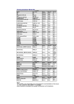
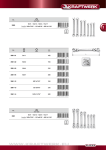
Owners Manual
POWER V6, POWER V8, POWER V12, POWER V12HP, POWER V15,
POWER VS10BP & POWER VS15BP
CONTENTS
1.0: IMPORTANT SAFETY INSTRUCTIONS
2.0: INTRODUCTION
3.0: THE BASICS
3.1
Unpacking and visual checks
3.2
Preliminary recommendation
5.1:
AC power requirements
5.2
Cooling
5.3
LED functions
5.4
Limiters
5.5
Audio Connections
4.0: INTERFACE PANEL
5.0: OPERATION
6.0: EQUALISATION
7.0: ARRAYING
8.0 DIMENSIONS
9.0: TECHNICAL SPECIFICATIONS
10.0: RIGGING
10.1 : SECUR ET - V6Y yoke bracket
10.2 : SECUR ET - V8Y yoke bracket
10.3 : SECUR ET - VMY yoke bracket
10.4 : SECUR ET - V15Y & V12Y
10.5 : SECUR ET - VMB wall mounting bracket
10.6 : SECUR ET - VEB eyebolt
10.7 : SECUR ET - VTH pole mount
10.8 : SECUR ET - VCS ceiling saddle
10.9 : SECUR ET - VPC pole clamp
11.0: SERVICE PARTS & ACCESSORIES
12.0: WARRANTY
13.0: DECLARATION OF CONFORMITY
14.0: NOTES
2
1.0: IMPORTANT SAFETY INSTRUCTIONS
The lightning flash with an arrowhead symbol within an
equilateral triangle, is intended to alert the user to the
presence of uninsulated “dangerous voltage” within the
product’s enclosure that may be of sufficient magnitude
to constitute a risk of electric shock to persons.
The exclamation point within an equilateral triangle is
intended to alert the user to the presence of important
operating and maintenance (servicing) instructions in the
literature accompanying the product.
IMPORTANT SAFETY INSTRUCTIONS
1
2
3
4
5
6
7
8
9
10
11
12
13
14
Read these instructions.
Keep these instructions.
Heed all warnings.
Follow all instructions.
Do not use this apparatus near water.
Clean only with dry cloth.
Do not block any ventilation openings. Install in accordance with the manufacturer's instructions.
Do not install near any heat sources such as radiators, heat registers, stoves or other apparatus (including amplifiers)
that produce heat.
Do not defeat the safety purpose of the polarized or grounding type plug. A polarized plug has two blades with one
wider than the other. A grounding type plug had two blades and a third grounding prong. The wide blade or the third
prong are provided for your safety. If the provided plug does not fit into your outlet, consult an electrician for replacement
of the obsolete outlet.
Protect the power cord from being walked on or pinched particularly at plugs, convenience receptacles and the point
where they exit from the apparatus.
Only use attachments / accessories specified by the manufacturer.
Use only with the cart, tripod, bracket or table specified by the manufacturer, or sold with the apparatus. When a cart
is used, use caution when moving the cart / apparatus combination to avoid injury from tip-over.
Unplug this apparatus during lightening storms or when unused for long periods of time.
Refer all servicing to qualified service personnel. Service is required when the apparatus has been damaged in any
way, such as power-supply cord or plug damaged, liquid has been spilled or objects have fallen into the apparatus,
this apparatus has been exposed to rain or moisture, does not operate normally, or has been dropped.
SAFETY WARNING
Permanent disconnection from the mains supply is to be achieved by removing the supplied cord connector from the back of
the unit.
SAFETY WARNING
Do not remove any covers, loosen any fixings or allow items to enter any aperture.
SAFETY WARNING
Objects filled with liquids should not be placed on this apparatus.
SAFETY WARNING
Replace the mains fuse only with the same T10A HBC type supplied by Tannoy under part number 34610919
SAFETY WARNING
The rear heatsink on this product gets hot. Avoid direct skin contact during operation and for at least 5 minutes after power
has been isolated.
AVERTISSEMENT DE SECURITE
Pour déconnecter l'appareil de l'alimentation principale de façon permanente, débranchez le connecteur du câble fourni à
l'arrière de l'appareil.
AVERTISSEMENT DE SECURITE
Ne retirez pas les couvercles, ne desserrez pas les fixations et ne laissez aucune pièce s'introduire dans les ouvertures.
AVERTISSEMENT DE SECURITE
Ne placez pas d'objets contenant du liquide à proximité de l'appareil.
AVERTISSEMENT DE SECURITE
Ne remplacez le fusible de réseau principal que par un fusible T10A HBC du même type fourni par Tannoy sous la référence
34610919.
AVERTISSEMENT DE SECURITE
Le radiateur arrière de cet appareil devient chaud. Evitez tout contact direct avec la peau pendant le fonctionnement et au
moins 5 minutes après la mise hors tension de l'appareil.
3
INSTALLATION INSTRUCTIONS
1
2
3
4
THIS PRODUCT MUST BE EARTHED. Use only a flexible cable or cord provided with a green or green and yellow core
which must be connected to the protective earthing terminal of the detachable Neutrik 'Powercon' type NEC3FCA
connector (Tannoy part number 3461 0919 as supplied with the equipment. The other end of the green or green and
yellow conductor must be connected to the earthing pin of a suitable mains plug or the earthing terminal of the installation.
The cord must be of maximum length 7.5 meters, rated SJ, SJT, or SJE, 10A minimum and be marked VW-1.
The electrical power connection to this product is only to be made via a detachable Neutrik 'Powercon' type NEC3FCA
connector (Tannoy part number 3461 0919) as supplied with the equipment. Wiring to this connector must only be made
by suitably qualified personnel and must comply with all local requirements.
Do not install this equipment in an enclosed space. Do not limit free ventilation and movement of air around the back
panel. Ensure that there is at least 100mm (4") of space around all sides of the product for ventilation.
Only use attachments and accessories approved by or specified by Tannoy.
FOR CUSTOMERS IN EUROPE
This product complies with both the LVD (electrical safety) 73/23/EEC and EMC (electromagnetic compatibility) 89/336/EEC
directives issues by the commission of the European community.
Compliance with these directives implies conformity with the following European standards:
EN60065
EN55103-1
EN55103-2
Product safety
EMC emissions
EMC immunity
This product is intended for the following electromagnetic environments: E2; E3 & E4. Environment E1 (domestic) is specifically
excluded.
FOR CUSTOMERS IN THE USA & CANADA
This product has been tested for electrical safety and complies with:
UL60065 7th edition
CA /CSA C22.2 No.60065-03
EMC
This equipment has been designed to comply with the limits for a Class A digital device, pursuant to part 15 of the FCC Rules.
These limits are designed to provide reasonable protection against harmful interference when the equipment is operated in a
commercial environment.
Industry Canada Class A emission compliance statement: This Class B digital apparatus complies with Canadian ICES-003.
Avis de conformite' a' la re'glementation d'Industrie Canada. Cet appareil nume'rique de classe A est conforme a' la norme
ICES-003.
2.0: INTRODUCTION
Power V™ is a range of active sound reinforcement loudspeakers equipped with the Tannoy Dual Concentric™, point source,
constant directivity drive unit technology. By combining the ‘Dual’ with a sophisticated amplifier package integrated within the
speaker cabinet, Power V™ is aimed at installation applications where uncompromised sound quality and flexibility is essential.
In order to satisfy a wide scope of fixed or on the road sound reinforcement applications there are five full range models and
two subwoofers in the Power V™ range; Power V6, Power V8, Power V12, Power V12HP and Power V15; along with the
subwoofers - Power VS10 BP and Power VS15 BP.
The location of the high frequency drive unit, in the throat of the low frequency driver, ensures that the driver delivers constant
directivity and unparalleled linearity from a true point source.
The spherical wave front delivered presents an even dispersion in both horizontal and vertical planes, providing exceptional
off-axis performance and an even response throughout a wide listening area. Overcoming the time alignment problems inherent
in a discretespeaker design the constant directivity characteristics of the ‘Dual’ exhibits better harmonic alignment, delivering
a more natural sound with superb tonal balance and greater intelligibility. This highly integrated driver design approach provides
a constant time delay over the frequency spectrum ensuring enhanced transient performance and sound quality.
4
All Power V™ loudspeakers are equipped with highly efficient, flexible and reliable Class D power amplification incorporating
switching power supplies. Optimally matched power supplies and power amplifier sections minimises noise and enhances
stability. Little is required in the way of heat sinking so the only surface area needed for cooling is the small control panel on
the rear of the cabinet; therefore, even when driven at very high power levels no fans are required, so the system runs quietly
and is not prone to internal dust contamination.
When used as a stand-alone speaker there is, on the rear panel of the full range Power V™ models, a mode switch for ‘Full
Range’.Alternatively the ‘High Pass’ position provides increased headroom for when the unit is used within close proximity to
a boundary and, in a simple setup, allows crossover to a subwoofer without the need for an external crossover.
LED’s on the rear panel indicate, signal pressence, signal activity, and power. Two low pass settings on the subwoofer amplifiers
fully optimise integration with the full range units.
Recessed carrying handles aid manoeuvrability and multiple flying points are incorporated to provide a quick and secure flying
system. Tannoy’s proprietary Secur-ET™ modular mounting hardware provides the Power V™ range with multiple hanging
options such as wall mount brackets, yoke fittings, ceiling saddles, pole clamps, pole mounts and eyebolts.
3.0: UNPACKING AND VISUAL CHECKS
Every Tannoy PowerV™ product is carefully tested and inspected before being packaged and leaving the factory. After
unpacking your loudspeaker, please inspect for any exterior physical damage, and save the carton and any relevant packaging
materials in case the loudspeaker again requires packing and shipping. In the event that damage has been sustained in transit
notify your dealer immediately.
3.1: PRELIMINARY RECOMMENDATION
A word of warning on high sound levels - these speakers are capable of generating high output levels over sustained periods
of time and such levels, over 95dBspl for 8 hours per day, can eventually cause permanent hearing loss. Since Tannoy
loudspeakers have a natural-sounding flat frequency response and low distortion, it's possible not to be aware just how high
the sound level is high while working with them.
For continuous exposure we recommend the occasional use of a sound level meter. This should be capable of integrating the
sound level over a period of exposure according to noise control standards and used just to check that noise levels are always
within safety limits.
4.0: INTERFACE PANEL
• XLR FEMALE AUDIO INPUT - This is a lockable XLR line input
socket for connection to the audio source. Fully balanced.
Pin 2 Hot (+), Pin 3 Cold (+), & Pin 1 Ground.
• XLR MALE AUDIO LINK - This is a lockable XLR line output socket
to link additional speakers. Fully Balanced.
Pin 2 Hot (+), Pin 3 Cold (+), & Pin 1 Ground.
• ROCKER POWER SWITCH - Turns AC power on to the unit (100V
- 240V)
• FUSE HOLDER - Replace only with 10A 230V anti-surge fuse.
• AC MAINS CONNECOR - Neutrik Powercon mains connector
(supplied)
• SIGNAL PRESENT LED - LED indicates when signal is being been
received by the speaker.
• LIMIT LED - LED indicates when the integral limiter is functioning
to protect the speaker.
FUSE HOLDER
• POWER LED - LED indicates when power has been applied to the
speaker.
ROCKER POWER SWITCH
XLR FEMALE AUDIO INPUT
LIMIT LED
SIGNAL LED
XLR MALE AUDIO LINK
NEUTRIK POWERCON
LOCKING MAINS CONNECOR
• MODE SWITCH - Switch allows the speaker to be toggled between
two modes;
• The subwoofers can either have an 80Hz or 110Hz low-pass
filter (LPF) filter activated.
• The full range speakers can either be run full range or have
a fixed high-pass filter (HPF) activated.
• LEVEL CONTROL - Control allows adjustment of the speaker volume.
MODE SWITCH
POWER LED
LEVEL CONTROL
5
5.0: OPERATION
The Power V™ range of products are integrated designs which include system specific EQ and protection circuitry, without
the need for external amplification. For room equalization, delay and other commissioning or setup functions, we recommend
you use a Vnet SC1 or TDX1 Digital Controller.
Below are example setups
6
5.1: AC POWER REQUIREMENTS
PowerV™ products are equipped with Neutrik Powercon™ mains connectors which mate with the Neutrik NAC3FCA Cable
connector, quick lock with a securing lever for power-in. This AC mains connector is supplied with each PowerV™ product.
The amplifier operates between the ranges of 100 to 240 Volts; the auto ranging power supply detects the mains voltage
automatically and configures accordingly. Replace the mains fuse only with the same T10A HBC type. It is necesary to have
power local to eacvh speaker, as it is not possible to daisy chain the AC power connections.
5.2 COOLING
Do not install this equipment in an enclosed space. Do not limit free ventilation and movement of air around the back panel.
Ensure that there is at least 100mm (4") of space around all sides of the product for ventilation. An efficient switch mode power
supply has less weight, less current draw and more efficient mechanical cooling; meaning that no fans are required.
5.3 LED FUNCTIONS
Power LED – When AC mains is connected to he speaker and the power switch is turned on the blue lower LED will illuminate.
Signal LED – The Green LED indicates that a useable signal is present at the input.
Limit LED - When illuminated this indicates that the system is approaching clipping.
An occasional flicker of the red LED on the loudest peaks is acceptable. If this LED remains red for more than the duration of
brief dynamic peaks, or lights continuously then the system is being overdriven.
If the red LED illuminates excessively:
• Reduce the input level (see interface panel)
• Reduce the output level of the mixer, or other source to the speaker.
5.4 LIMITERS
The limiters are carefully set-up to preserve the loudspeakers dynamic headroom by allowing short term transients to pass;
audible degradation in sound will only become apparent when the limit indication is on constantly. The limiting functions will
protect the amplifier from long term overheating by attenuating the driving voltage to the drive units. If used irresponsibly
(constant hard clipping) sound quality will be compromised. In extreme cases drive units may also be damaged.
5.5: AUDIO CONNECTIONS
Audio Connections
The signal input & link connectors are fully balanced.
When connecting a balanced signal be sure to wire
to the following standard:-
SIGNAL
Hot (+)
Cold (-)
Shield (GND)
XLR CONNECTOR
Pin 2
Pin 3
Pin 1
In a standard balanced interconnection there are two signal conductors and a shield. The shield is normally referenced to
ground at one or both ends. Many times the shield is lifted at one end, usually at the input to eliminate "ground loops" or noise.
The problem with this approach is that while it may reduce hum, the shields act as radio antennas and pickup radio frequency
interference from the environment.
Multiple enclosures may be driven from a single audio source; simply plug the signal source output into the first XLR input
socket, and patch that speakers XLR link to the next speakers XLR input socket & so on.
6.0: EQUALISATION
PowerV™ loudspeakers are designed to need no equalisation or correction to overcome system limitations. As a result, they
will only need equalisation to compensate for difficult acoustic environments.
Over equalisation can reduce system headroom, and introduce phase distortion resulting in greater problems than cures. If
equalisation is required then it should be applied gently and smoothly. PowerV™ full range loudspeakers are point source,
phase coherent designs and violent equalisation will be detrimental to the overall sound quality. When a loudspeaker is used
in close proximity to another, comb filtering effects can create coverage problems; comb filtering creates an uneven frequency
response across the coverage area due to constructive and destructive interference effects between the sources. The amount
of comb filtering is affected by the spacing of the relative sound sources. Minimising this effect cannot be cured by equalisation
(see the following section for more details).
7
7.0: ARRAYING
As discussed in the previous section, comb filtering cannot be cured by equalisation. Small alterations to loudspeaker positions
can have the effect of minimising problematic combing frequencies. Arrays should be constructed so that the individual coverage
patters of each loudspeaker combine with minimal overlap. The design of the PowerV™ cabinet greatly simplifies the creation
of effective arrays, allowing seamless wide horizontal coverage using two loudspeakers without the need for tedious
experimentation.
By placing the PowerV™ cabinets with the 30 degree angled rear panels together, minimal dispersion pattern overlap is
achieved, guaranteeing an extraordinarily smooth transition. In many applications the 90-degree (75 - degree on the
PowerV12HP™ and PowerV15™) dispersion pattern may be sufficient in the horizontal plane.
It is also possible to stack the cabinets vertically using the above method, say for use in a central cluster, where greater vertical
dispersion is required.
As shown in the above diagram, one of the PowerV™ cabinets is inverted to allow the optimum splay angle to be achieved.
The grill can be simply removed from this cabinet and be replaced in the correct orientation. The grill is held in position by
the two fixing screws on the top and bottom lips of the cabinet.
8
8.0 DIMENSIONS
POWER V6
240.8
[9.48"]
WARNING
CAUTION
TO REDUCE THE RISK OF FIRE OR ELECTRIC
SHOCK DO NOT EXPOSE THIS EQUIPMENT TO
RAIN OR MOISTURE
AVIS: RISQUE DE CHOC ELECTRIQUE-NE PAS
OUVRIR.
THIS CLASS D DIGITAL DEVICE MEETS ALL REQUIREMENTS OF THE
CANADIAN INTERFERENCE-CAUSING EQUIPMENT REGULATIONS AND
COMPLIES WITH PART 15 OF THE FCC RULES.
OPERATION SUBJECT TO CONDITIONS STATED IN THE MANUAL.
THIS EQUIPMENT MUST BE EARTHED
334.0
[13.15"]
296.0
[11.65"]
FUSE
235.0
[9.25"]
T10AL 250V
REPLACE ONLY WITH
TANNOY PART 3461 0913
POWER
LINK
0
B
A
125.0
[4.92"]
- LIMIT
- SIGNAL
MODE
INPUT
LEVEL
- POWER
10
115-230V
MODE A
MODE B
FULL
RANGE
HIGH PASS
FILTER
IN
500VA Max
50-60Hz
T E RT E K
CM
U
S
C
LI S T E D
154.0
[6.06"]
15º
15º
POWER V8
154.0
[6.01"]
30º
45º
WARNING
CAUTION
TO REDUCE THE RISK OF FIRE OR ELECTRIC
SHOCK DO NOT EXPOSE THIS EQUIPMENT TO
RAIN OR MOISTURE
AVIS: RISQUE DE CHOC ELECTRIQUE-NE PAS
OUVRIR.
THIS CLASS D DIGITAL DEVICE MEETS ALL REQUIREMENTS OF THE
CANADIAN INTERFERENCE-CAUSING EQUIPMENT REGULATIONS AND
COMPLIES WITH PART 15 OF THE FCC RULES.
OPERATION SUBJECT TO CONDITIONS STATED IN THE MANUAL.
THIS EQUIPMENT MUST BE EARTHED
388.0
[15.13"]
145.0
[5.66"]
296.0
[11.54"]
275.0
[10.73"]
FUSE
T10AL 250V
REPLACE ONLY WITH
TANNOY PART 3461 0913
POWER
- LIMIT
- SIGNAL
MODE
INPUT
LINK
A
0
B
LEVEL
- POWER
10
115-230V
MODE A
MODE B
FULL
RANGE
HIGH PASS
FILTER
IN
500VA Max
50-60Hz
T E R TE K
CM
US
C
LI S T E D
180.0
[7.02"]
POWER VS10BP
590.0
[23.23"]
365.0
[14.37"]
185.0
[7.28"]
154.0
[6.06"]
42.5
[1.67"]
220.0
[8.66"]
WARNING
CAUTION
TO REDUCE THE RISK OF FIRE OR ELECTRIC
SHOCK DO NOT EXPOSE THIS EQUIPMENT TO
RAIN OR MOISTURE
AVIS: RISQUE DE CHOC ELECTRIQUE-NE PAS
OUVRIR.
THIS CLASS D DIGITAL DEVICE MEETS ALL REQUIREMENTS OF THE
CANADIAN INTERFERENCE-CAUSING EQUIPMENT REGULATIONS AND
COMPLIES WITH PART 15 OF THE FCC RULES.
OPERATION SUBJECT TO CONDITIONS STATED IN THE MANUAL.
THIS EQUIPMENT MUST BE EARTHED
296.0
[11.65"]
355.0
[13.98"]
280.0
[11.02"]
FUSE
T10AL 250V
182.5
[7.19"]
REPLACE ONLY WITH
TANNOY PART 3461 0913
POWER
- LIMIT
- SIGNAL
MODE
INPUT
LINK
A
0
B
LEVEL
- POWER
10
115-230V
MODE A
MODE B
LPF 1
80Hz
LPF 2
110Hz
IN
500VA Max
50-60Hz
T E RTE K
CM
C
LI S T E D
U
S
295.0
[11.61"]
42.5
[1.67"]
POWER V12
180.0
[7.09"]
WARNING
CAUTION
TO REDUCE THE RISK OF FIRE OR ELECTRIC
SHOCK DO NOT EXPOSE THIS EQUIPMENT TO
RAIN OR MOISTURE
AVIS: RISQUE DE CHOC ELECTRIQUE-NE PAS
OUVRIR.
THIS CLASS D DIGITAL DEVICE MEETS ALL REQUIREMENTS OF THE
CANADIAN INTERFERENCE-CAUSING EQUIPMENT REGULATIONS AND
COMPLIES WITH PART 15 OF THE FCC RULES.
OPERATION SUBJECT TO CONDITIONS STATED IN THE MANUAL.
THIS EQUIPMENT MUST BE EARTHED
486.0
[19.13"]
406.0 180.0
[15.98"] [7.09"]
359.0
[14.13"]
FUSE
T10AL 250V
REPLACE ONLY WITH
TANNOY PART 3461 0913
360.0
[14.17"]
POWER
153.0
[6.02"]
- LIMIT
- SIGNAL
MODE
INPUT
LINK
A
B
0
LEVEL
- POWER
10
115-230V
MODE A
MODE B
FULL
RANGE
HIGH PASS
FILTER
500VA Max
50-60Hz
IN
T E R TE K
CM
175.0
[6.89"]
US
C
LI S T E D
40.0
[1.57"]
34.0
[1.34"]
175.0
[6.89"]
186.1
[7.33"]
30º
154.0
[6.06"]
50º
9
8.0 DIMENSIONS
POWER V12HP
180.0
[7.09"]
WARNING
CAUTION
TO REDUCE THE RISK OF FIRE OR ELECTRIC
SHOCK DO NOT EXPOSE THIS EQUIPMENT TO
RAIN OR MOISTURE
AVIS: RISQUE DE CHOC ELECTRIQUE-NE PAS
OUVRIR.
THIS CLASS D DIGITAL DEVICE MEETS ALL REQUIREMENTS OF THE
CANADIAN INTERFERENCE-CAUSING EQUIPMENT REGULATIONS AND
COMPLIES WITH PART 15 OF THE FCC RULES.
OPERATION SUBJECT TO CONDITIONS STATED IN THE MANUAL.
THIS EQUIPMENT MUST BE EARTHED
486.0
[19.13"]
406.0 180.0
[15.98"] [7.09"]
359.0
[14.13"]
360.0
[14.17"]
FUSE
T10AL 250V
REPLACE ONLY WITH
TANNOY PART 3461 0913
POWER
153.0
[6.02"]
LINK
A
B
175.0
[6.89"]
- LIMIT
- SIGNAL
MODE
INPUT
0
LEVEL
- POWER
10
115-230V
MODE A
MODE B
FULL
RANGE
HIGH PASS
FILTER
500VA Max
50-60Hz
IN
T E R TE K
CM
US
C
LI S T E D
34.0
[1.34"]
175.0
[6.89"]
186.1
[7.33"]
50º
30º
154.0
[6.06"]
POWER V15
450.0
[17.72"]
370.0
[14.57"]
180.0
[7.09"]
WARNING
CAUTION
TO REDUCE THE RISK OF FIRE OR ELECTRIC
SHOCK DO NOT EXPOSE THIS EQUIPMENT TO
RAIN OR MOISTURE
AVIS: RISQUE DE CHOC ELECTRIQUE-NE PAS
OUVRIR.
THIS CLASS D DIGITAL DEVICE MEETS ALL REQUIREMENTS OF THE
CANADIAN INTERFERENCE-CAUSING EQUIPMENT REGULATIONS AND
COMPLIES WITH PART 15 OF THE FCC RULES.
OPERATION SUBJECT TO CONDITIONS STATED IN THE MANUAL.
THIS EQUIPMENT MUST BE EARTHED
590.0
[23.23"]
510.0
[20.08"]
180.0
[7.09"]
359.0
420.0
[16.54"]
[14.13"]
FUSE
T10AL 250V
REPLACE ONLY WITH
TANNOY PART 3461 0913
200.0
[7.87"]
POWER
205.0
[8.07"]
- LIMIT
- SIGNAL
MODE
INPUT
LINK
A
B
0
LEVEL
- POWER
10
115-230V
MODE A
MODE B
FULL
RANGE
HIGH PASS
FILTER
500VA Max
50-60Hz
IN
T E R TE K
CM
US
C
LI S T E D
40.0
[1.57"]
200.0
[7.87"]
40.0
[1.57"]
30º
225.0
[8.86"]
50º
154.0
[6.06"]
POWER VS15BP
400.0
[15.75"]
40.0
[1.57"]
WARNING
CAUTION
TO REDUCE THE RISK OF FIRE OR ELECTRIC
SHOCK DO NOT EXPOSE THIS EQUIPMENT TO
RAIN OR MOISTURE
AVIS: RISQUE DE CHOC ELECTRIQUE-NE PAS
OUVRIR.
THIS CLASS D DIGITAL DEVICE MEETS ALL REQUIREMENTS OF THE
CANADIAN INTERFERENCE-CAUSING EQUIPMENT REGULATIONS AND
COMPLIES WITH PART 15 OF THE FCC RULES.
OPERATION SUBJECT TO CONDITIONS STATED IN THE MANUAL.
THIS EQUIPMENT MUST BE EARTHED
665.0
[26.18"]
625.0
[24.61"]
FUSE
T10AL 250V
REPLACE ONLY WITH
TANNOY PART 3461 0913
POWER
- LIMIT
- SIGNAL
MODE
INPUT
LINK
A
0
B
LEVEL
- POWER
10
115-230V
MODE A
MODE B
LPF 1
80Hz
LPF 2
110Hz
500VA Max
50-60Hz
IN
T E R TE K
CM
US
C
LI S T E D
40.0
[1.57"]
440.0
[17.32"]
10
195.0
[7.68"]
440.0
[17.32"]
38.5
[1.52"]
220.0
[8.66"]
195.0
[7.68"]
9.0 TECHNICAL SPECIFICATIONS
SYSTEM
Power V6
Power V8
Power V12
Power V12HP
Power V15
System Type
Full Range - Vented
Full Range - Vented
Full Range - Vented
Full Range - Vented
Full Range - Vented
Frequency Response (-3dB) 1 85Hz - 35kHz
Full Range Mode
80Hz - 30kHz
70Hz - 25kHz
71Hz - 23kHz
60Hz - 23kHz
78Hz - 45kHz
67Hz - 40kHz
55Hz - 38kHz
62Hz - 28kHz
47Hz - 26kHz
Frequency Response (-3dB) 1 120Hz - 35kHz
High Pass Mode
120Hz - 30kHz
100Hz - 30kHz
100Hz - 23kHz
100Hz - 23kHz
Frequency Range (-10dB) 1
High Pass Mode
100Hz - 45kHz
100Hz - 40kHz
80Hz - 38kHz
80Hz - 28kHz
80Hz - 26kHz
Rated Maximum SPL
107dB (average) 113dB (peak)
113dB (average) 119dB (peak)
120dB (average) 126dB (peak)
124dB (average) 130dB (peak)
126dB (average) 132dB (peak)
Dispersion (-6dB)
90 Degrees Conical
90 Degrees Conical
90 Degrees Conical
75 Degrees Conical
75 Degrees Conical
Driver Complement
1 x 150mm (6 ) Dual Concentric™
1 x 200mm (8 ) Dual Concentric™
1 x 300mm (12 ) Dual Concentric™ 1 x 300mm (12 ) PowerDual™
1 x 380mm (15 )PowerDual™
Directivity Factor (Q)
5.6 averaged 1kHz to 10kHz
6.8 averaged 1kHz to 10kHz
8.2 averaged 1kHz to 10kHz
8.2 averaged 1kHz to 10kHz
7.8 averaged 1kHz to 10kHz
Directivity Index (DI)
7.0 averaged 1kHz to 10kHz
7.9 averaged 1kHz to 10kHz
8.8 averaged 1kHz to 10kHz
9.1 averaged 1kHz to 10kHz
8.9 averaged 1kHz to 10kHz
Distortion
10% Full Power (8.9V)
250Hz
1kHz
10kHz
2nd Harmonic 3rd Harmonic
2.64%
0.31%
0.22%
0.45%
1.87%
0.29%
2nd Harmonic 3rd Harmonic
0.12%
0.15%
0.23%
0.84%
1.35%
0.16%
2nd Harmonic 3rd Harmonic
0.56%
0.23%
2.36%
1.88%
2.68%
0.08%
2nd Harmonic 3rd Harmonic
0.04%
0.58%
0.80%
2.64%
2.11%
0.11%
2nd Harmonic 3rd Harmonic
1.00%
0.50%
1.40%
1.00%
3.98%
1.78%
1% Full Power (2.8V)
250Hz
1kHz
10kHz
2nd Harmonic 3rd Harmonic
0.63%
0.31%
0.06%
0.23%
0.78%
0.26%
2nd Harmonic 3rd Harmonic
0.16%
0.14%
0.09%
0.53%
0.53%
0.17%
2nd Harmonic 3rd Harmonic
0.14%
0.14%
0.38%
0.94%
1.03%
0.05%
2nd Harmonic 3rd Harmonic
0.24%
0.67%
1.80%
4.11%
5.21%
0.21%
2nd Harmonic 3rd Harmonic
0.32%
0.45%
0.45%
0.79%
3.16%
0.31%
Crossover
1.6kHz Passive
1.7kHz Passive
1.4kHz Passive
1.75kHz Passive
Passive 1.4kHz
Frequency Range (-10dB) 1
Full Range Mode
Notes
1. Average over stated bandwidth. Measured at 1 metre on axis.
2. Unweighted pink noise input, measured at 1 metre in an anechoic chamber
A full range of measurements, performance data, and Ease!™ Data can be downloaded from www.tannoy.com Tannoy operates a policy of continuous research and development. The introduction of new materials or manufacturing methods will always equal or exceed the published specifications, which Tannoy reserves the right to alter without prior
CONSTRUCTION
Enclosure
11.3 litre MDF, Vented,
Internally Braced
17 litre vented, 15mm (5/8 ) birch
37.5 litre vented, 15mm (5/8 ) birch 37.5 litre vented, 15mm (5/8 ) birch 62 litre vented, 15mm (5/8 ) birch
plywood and 15mm (5/8 ) MDF front plywood and 15mm (5/8 ) MDF front plywood and 15mm (5/8 ) MDF front plywood and 15mm (5/8 ) MDF front
baffle.Vented, Internally braced.
baffle.Vented, Internally braced.
baffle.Vented, Internally braced.
baffle. Vented, Internally braced.
Finish
Textured Black or White paint
(Custom colours on request).
Powder Coated Steel Grill
(reticulated foam behind)
Textured Black or White paint
(Custom colours on request).
Powder Coated Steel Grill
(reticulated foam behind)
Connectors
1 x female XLR (input),1 male XLR
(link), 1 x Neutrik Powercon
1 x female XLR (input), 1 male XLR 1 x female XLR (input), 1 male XLR 1 x female XLR (input), 1 male XLR 1 x female XLR (input), 1 male XLR
(link), 1 x Neutrik Powercon
(link), 1 x Neutrik Powercon
(link), 1 x Neutrik Powercon
(link), 1 x Neutrik Powercon
Controls & Indicators
Level Control
Power LED (Blue)
Signal LED (Green)
Limit LED (Red)
Full Range / HighPass Switch (110Hz)
Power Switch
Level Control
Power LED (Blue)
Signal LED (Green)
Limit LED (Red)
Full Range / HighPass Switch (110Hz)
Power Switch
Level Control
Power LED (Blue)
Signal LED (Green)
Limit LED (Red)
Full Range / HighPass Switch (110Hz)
Power Switch
Level Control
Power LED (Blue)
Signal LED (Green)
Limit LED (Red)
Full Range / HighPass Switch (110Hz)
Power Switch
Level Control
Power LED (Blue)
Signal LED (Green)
Limit LED (Red)
Full Range / HighPass Switch (110Hz)
Power Switch
Fittings
4 x M6 bracket inserts,
2 x M6 yoke bracket inserts
4 x M10 Flying inserts, 2 x M10 yoke
bracket inserts 1 x recessed carrying
handle Blanking plate for optional
VTH, pole mount
8 x M10 Flying inserts, 8 x M10 yoke
bracket inserts 3 x recessed carrying
handles (2 side & 1 rear) Blanking
plate for optional VTH, pole mount
8 x M10 Flying inserts, 8 x M10 yoke
bracket inserts 3 x recessed carrying
handles (2 side & 1 rear) Blanking
plate for optional VTH, pole mount
8 x M10 Flying inserts, 8 x M10 yoke
bracket inserts 3 x recessed carrying
handles (2 side & 1 rear) Blanking
plate for optional VTH, pole mount
Dimensions
337 x 252 x 240mm
13.26 x 9.92 x 9.44”
338 x 280 x 275mm
15.28x11.02x10.83”
486 x 370 x 375mm
19.13x14.57x15.5”
486 x 370 x 375mm
19.13x14.57x15.5”
590 x 450 x 420mm
23.23x17.72x16.54”
Weight
8.5kg (18.7lbs)
10.5kg (23.1lbs)
23kg (50.6lbs)
23kg (50.6lbs)
35kg (77lbs)
Input attenuator at
minimum - +18dBu
Input attenuator at
Maximum - +5dBu
Input attenuator at
minimum - +18dBu
Input attenuator at
Maximum - +5dBu
Input attenuator at
minimum - +18dBu
Input attenuator at
Maximum - +5dBu
Input attenuator at
minimum - +18dBu
Input attenuator at
Maximum - +5dBu
Textured Black or White paint (Custom
colours on request).
Powder Coated Steel Grill (reticulated
foam behind)
Textured Black or White paint (Custom
colours on request).
Powder Coated Steel Grill (reticulated
foam behind)
Textured Black or White paint (Custom
colours on request).
Powder Coated Steel Grill (reticulated
foam behind)
ELECTRONICS
Maximum signal input for clip Input attenuator at
minimum - +18dBu
Input attenuator at
Maximum - +5dBu
Output noise
-105dB unweighted, referenced to -105dB unweighted, referenced to -105dB unweighted, referenced to -105dB unweighted, referenced to -105dB unweighted, referenced to
maximum output (22kHz bandwidth) maximum output (22kHz bandwidth) maximum output (22kHz bandwidth) maximum output (22kHz bandwidth) maximum output (22kHz bandwidth)
Efficiency
>90% typically
>90% typically
>90% typically
>90% typically
>90% typically
Damping Factor
400 ref 8 Ohms
400 ref 8 Ohms
400 ref 8 Ohms
400 ref 8 Ohms
400 ref 8 Ohms
Distortion
<0.05% @ 1kHz -3dB output
(22kHz bandwidth)
<0.05% @ 1kHz -3dB output
(22kHz bandwidth)
<0.05% @ 1kHz -3dB output (22kHz <0.05% @ 1kHz -3dB output (22kHz <0.05% @ 1kHz -3dB output (22kHz
bandwidth)
bandwidth)
bandwidth)
Input Impedance
5.6kOhms unbalanced,
11.2kOhms balanced
5.6kOhms unbalanced,
11.2kOhms balanced
5.6kOhms unbalanced,
11.2kOhms balanced
5.6kOhms unbalanced,
11.2kOhms balanced
5.6kOhms unbalanced,
11.2kOhms balanced
Excessive over current causes
shutdown
Limiters applied
Automatic protection & recovery
Inrush current limiting
1x Limit LED, 1x Signal LED &
1x Power LED
Excessive over current causes
shutdown
Limiters applied
Automatic protection & recovery
Inrush current limiting
1x Limit LED, 1x Signal LED & 1x
Power LED
Excessive over current causes
shutdown
Limiters applied
Automatic protection & recovery
Inrush current limiting
1x Limit LED, 1x Signal LED & 1x
Power LED
Excessive over current causes
shutdown
Limiters applied
Automatic protection & recovery
Inrush current limiting
1x Limit LED, 1x Signal LED & 1x
Power LED
Excessive over current causes
shutdown
Limiters applied
Automatic protection & recovery
Inrush current limiting
1x Limit LED, 1x Signal LED & 1x
Power LED
Number of channels
one
one
one
one
one
System Type
Class D
Class D
Class D
Class D
Class D
Locking Neutrik Powercon
Automatic (115 / 230V, 45 - 65Hz)
High current, high freq. switch-mode
>90% typical
100V / 115V / 230V nominal +/-10%
External
T10AT
Automatic soft-start
Locking Neutrik Powercon
Automatic (115 / 230V, 45 - 65Hz)
High current, high freq. switch-mode
>90% typical
100V / 115V / 230V nominal +/-10%
External
T10AT
Automatic soft-start
Locking Neutrik Powercon
Automatic (115 / 230V, 45 - 65Hz)
192kHz Syncronised to DSP
High current, high freq. switch-mode
>90% typical
100V / 115V / 230V nominal +/-10%
External
T10AT
Automatic soft-start
Locking Neutrik Powercon
Automatic (115 / 230V, 45 - 65Hz)
High current, high freq. switch-mode
>90% typical
100V / 115V / 230V nominal +/-10%
External
T10AT
Automatic soft-start
Locking Neutrik Powercon
Automatic (115 / 230V, 45 - 65Hz)
High current, high freq. switch-mode
>90% typical
100V / 115V / 230V nominal +/-10%
External
T10AT
Automatic soft-start
Protection systems
Over Current
Temperature
Brownout
Mains
Indicators
PSU SPECIFICATIONS
Input Connector
Voltage Selection
Type
Efficiency
Input voltage
Mains fuse
Fuse type
Other features
11
9.0 TECHNICAL SPECIFICATIONS (CONTINUED)
SYSTEM
Power Vs10BP
Power Vs15BP
System Type
Subwoofer-Bandpass
Subwoofer-Bandpass
Frequency Response (-3dB) 1
Lowpass Filter A on
37Hz - 80Hz
47Hz - 80Hz
Frequency Response (-3dB) 1
Lowpass Filter B on
37Hz - 110Hz
47Hz - 110Hz
Frequency Response (-10dB) 1
Lowpass Filter A on
32Hz - 80Hz
37Hz - 80Hz
Frequency Response (-10dB) 1
Lowpass Filter B on
32Hz - 110Hz
37Hz - 110Hz
Rated Maximum SPL
118dB (average) 124dB (peak)
124dB (average) 130dB (peak)
Driver Complement
1 x 250mm (10”) High excursion bass driver
1 x 380mm (15”) High excursion bass driver
Crossover
User Selectable LPF
User Selectable LPF
Distortion
10% Full Power (12.7V)
40Hz
100Hz
2nd Harmonic 3rd Harmonic
2.27%
0.73%
1.79%
1.27%
2nd Harmonic 3rd Harmonic
0.65%
0.67%
3.05%
0.70%
1% Full Power (4V)
40Hz
100Hz
2nd Harmonic 3rd Harmonic
0.57%
0.47%
0.61%
1.37%
2nd Harmonic 3rd Harmonic
0.13%
0.30%
0.76%
0.24%
Notes
1. Average over stated bandwidth. Measured at 1 metre on axis.
2. Unweighted pink noise input, measured at 1 metre in an anechoic chamber
A full range of measurements, performance data, and Ease!" Data can be downloaded from www.tannoy.com Tannoy operates a policy of continuous research and development. The introduction of new materials or manufacturing methods will always equal or exceed the published specifications, which Tannoy reserves the right to alter without prior
CONSTRUCTION
Enclosure
50 litre Bandpass, 15mm (5/8) birch plywood. Internally braced.
100 litre Bandpass, 15mm (5/8”) birch plywood. Internally braced.
Finish
Textured Black or White paint (Custom colours on request).
Textured Black or White paint (Custom colours on request).
Connectors
1 x female XLR (input), 1 male XLR (link), 1 x Neutrik Powercon
1 x female XLR (input), 1 male XLR (link), 1 x Neutrik Powercon
Controls & Indicators
Level Control
Power LED (Blue)
Signal LED (Green)
Limit LED (Red)
Full Range / HighPass Switch (110Hz)
Power Switch
Level Control
Power LED (Blue)
Signal LED (Green)
Limit LED (Red)
Full Range / HighPass Switch (110Hz)
Power Switch
Fittings
2 x Blanking plates, this allows the bass ports to be moved to another facia
8 x M10 Flying inserts
2 x recessed carrying handles
Blanking plate for optional VTH, pole mount
4 x Rubber Feet
2 x Blanking plates, this allows the bass ports to be moved to another facia
8 x M10 Flying inserts
2 x recessed carrying handles
Blanking plate for optional VTH, pole mount
4 x Rubber Feet
Dimensions
335 x 365 x 590mm
14 x 14.4 x 23.25”
665 x 440 x 440mm
26.18 x 17.3 x 17.3”
Weight
18kg (39.6lbs)
30kg (66lbs)
Input attenuator at minimum - +18dBu
Input attenuator at Maximum - +5dBu
Input attenuator at minimum - +18dBu
Input attenuator at Maximum - +5dBu
ELECTRONICS
Maximum signal input for clip
Output noise
-105dB unweighted, referenced to maximum output (22kHz bandwidth)
-105dB unweighted, referenced to maximum output (22kHz bandwidth)
Efficiency
>90% typically
>90% typically
Damping Factor
400 ref 8 Ohms
400 ref 8 Ohms
Distortion
<0.05% @ 1kHz -3dB output (22kHz bandwidth)
<0.05% @ 1kHz -3dB output (22kHz bandwidth)
Input Impedance
5.6kOhms unbalanced, 11.2kOhms balanced
5.6kOhms unbalanced, 11.2kOhms balanced
Protection systems
Over Current
Temperature
Brownout
Mains
Indicators
Excessive over current causes shutdown
Limiters applied
Automatic protection & recovery
Inrush current limiting
1x Limit LED, 1x Signal LED & 1x Power LED
Excessive over current causes shutdown
Limiters applied
Automatic protection & recovery
Inrush current limiting
1x Limit LED, 1x Signal LED & 1x Power LED
Number of channels
one
one
System Type
Class D
Class D
Locking Neutrik Powercon
Automatic (115 / 230V, 45 - 65Hz)
High current, high freq. switch-mode
>90% typical
100V / 115V / 230V nominal +/-10%
External
T10AT
Automatic soft-start
Locking Neutrik Powercon
Automatic (115 / 230V, 45 - 65Hz)
High current, high freq. switch-mode
>90% typical
100V / 115V / 230V nominal +/-10%
External
T10AT
Automatic soft-start
PSU SPECIFICATIONS
Input Connector
Voltage Selection
Type
Efficiency
Input voltage
Mains fuse
Fuse type
Other features
12
10.0: RIGGING
The Tannoy Professional hardware covered in this guide has been designed to offer quick, simple, cost
effective and secure solutions for mounting specific Tannoy Professional loudspeakers. This hardware has
been designed and manufactured with a high safety load factor for its specific role. To ensure the safest
possible use of the hardware covered in this guide, it must be assembled in strict accordance with the
instructions specified. The information in these manuals relating to the assembly and the safe use of these
accessories must be understood and followed. The installation of Tannoy Professional loudspeakers using
the dedicated hardware should only ever be carried out by fully qualified installers, in accordance with all
the required safety codes and standards that are applied at the place of installation.
WARNING: As the legal requirements for flying change from country to country, please consult you local safety standards
office before installing any product. We also recommend that you thoroughly check any laws and bylaws prior to commencing
work.
Tannoy Professional hardware has been designed for use with specific Tannoy Professional loudspeakers, and is not designed
or intended for use with any other Tannoy Professional products, or any other devices. Using Tannoy Professional hardware
for any purpose other than that indicated in this guide is considered to be improper use. Such use can be very dangerous as
overloading, modifying; assembling in anyway other than that clearly stated in the manual, or damaging Tannoy Professional
hardware will compromise safety.
The component parts of any Tannoy Professional hardware device must only be assembled using the accessory kits supplied
and in strict compliance with the user manual. The use of other accessories or non-approved methods of assembly may result
in an unsafe hardware system by reducing the load safety factor. Welding, or any other method of permanently fixing hardware
components together or to the integral fixing points in the cabinet should never be used.
Whenever a Tannoy Professional loudspeaker is fixed to a surface using a Tannoy Professional hardware device, the installer
must ensure that the surface is capable of safely and securely supporting the load. The hardware employed must be safely,
securely, and in accordance with the manual, attached both to the loudspeaker and also to the surface in question, using only
the fixing holes provided as standard and covered in the manual. Secure fixings to the building structure are vital. Seek help
from architects, structural engineers or other specialists if in any doubt.
All loudspeakers flown in theatres, nightclubs, conference centre or other places of work and entertainment must, be provided
with an independent, correctly rated and securely attached secondary safety - in addition to the principle hardware device.
This secondary safety must prevent the loudspeaker from dropping more than 150mm (6”) should the principle hardware device
fail.
10.1: SECUR ET™ - V6Y YOKE BRACKET
The V6Y is a discreet yoke style bracket, available in both black and white, and is used to mount the Tannoy V6 in both portrait
and landscape orientations. The Tannoy V6 loudspeaker is fixed to the bracket using the M6 bolts and washers supplied in
the accessory pack
Only the screws, fasteners, shakeproof and plain washers specified on figure 3. should be used to assemble the VMY bracket.
The arms of the V6Y have long slots, through which M6 bolts are fitted, and screwed into the integral M6 inserts in the top
and bottom of the Tannoy V6 cabinet.
13
These slots allow the installer to easily and precisely adjust the distance between the loudspeaker and the mounting surface
for optimal discreet installation of the Tannoy V6.
Use the 20mm hole to pass the loudspeaker cable through before fixing the bracket to the wall.
Use the table of parts along with the
assembly drawing to assemble the V6Y.
ASSEMBLY VIEW
DESCRIPTION
QUANTITY
1
Yoke Bracket
1
2
Washer M6 Plain
2
3
Washer M6 Spring
2
4
M6 x 25 Button Head Screw
2
5
Rubber Friction Washer
2
10.2: SECUR ET: V8Y YOKE BRACKET
VCB2: The VCB2 cluster bar is available in both black and white finishes and provides a platform onto which 2 x Tannoy V6
loudspeakers can be mounted using the V6Y yoke bracket (not supplied in the VCB2 kit). A number of different loudspeaker
arrangements can be made depending on the application and the coverage pattern required (see figures 1 & 2).
Using the VCS ceiling saddle the resulting cluster can be attached to the ceiling.
VCB4: The VCB4 cluster bar (available in both black and white) provides the platform onto which 3-4 x Tannoy V6 loudspeakers
can be mounted using the V6Y yoke bracket (not supplied in the VCB4 kit). A number of different loudspeaker arrangements
can be made depending on the application and the coverage pattern required (see figures 3-6).
N.B. When using the VCB4 cluster bar system, one of the cluster bars is mounted above the other to produce a cross formation.
To ensure an equal mounting height, the 2 x Tannoy V6 loudspeakers being flown from the lower cluster bar should be attached
to the upper surface of this bar. While the 2 x Tannoy V6 loudspeakers being flown from the upper bar should be attached to
the underside of this cluster bar.
Using the VCS ceiling saddle the resulting cluster can be attached to the ceiling.
14
Fig. 1.
Fig. 3.
Fig. 5.
Fig. 2.
Fig. 6.
Contents of VCB2
DESCRIPTION
QUANTITY
1
Cluster Bar
1
2
Washer M10 Plain
2
3
Screw M10x40 Button Head
2
4
M10 Nyloc Nut
2
5
Blanking Plug
2
Contents of VCB4
DESCRIPTION
QUANTITY
1
Cluster Bar
1
2
Washer M10 Plain
2
3
Screw M10x40 Button Head
2
4
M10 Nyloc Nut
2
5
Blanking Plug
2
15
10.3: SECUR ET - VMY YOKE BRACKET
Fig.1
Fig.2
Use the table of parts along with the assembly drawing (Figure 3.) to assemble the VMY.
Figure 4 shows the VMY assembled.
Fig.3
16
Number on Assembly View (Fig 3.)
1
2
3
4
5
6
7
8
9
10
11
12
Fig.4
Description
Hanging Bracket
Cross Member
Pivot Stud
M10 Plain Washer
M8 Spring Washer
M10 Spring Washer
M10 x 30mm Screw
M8 x 20mm Screw
M10 x 30mm Screw
M10 Nyloc Nut
Friction Washer
30mm Square Blank Plug
Quantity
2
1
2
2
2
4
2
2
2
2
2
2
10.4: SECUR ET - V15Y & V12Y
V15Y
V12Y
17
10.5 : SECUR ET - VMB WALL MOUNTING BRACKET
FIG 1.
The VMB is wall mounting bracket for the attachment of a VMY,
available in both black and white finishes, allowing the user secure
the Tannoy Power V™ Full range loudspeaker in either portrait or
landscape orientations to a wall.
The Tannoy Power V™ loudspeaker is attached to the bracket using
the accessories supplied.
This wall-mounting bracket has a larger wall plate than previous
models to maximise the integrity of fixing obtained. There are also
two holes either side of the fixing beam to allow the speaker cable
the pass through the wall plate and along the fixing beam to the
terminal panel resulting in a more discrete installation.
The fixing beam on the VMB has a number of mounting points from
which the VMY, V12Y & V15Y can be attached at varying distances
from the mounting surface.
Only the screws, fasteners, shakeproof and plain
washers specified on figure 3. should be used to
assemble the VMB bracket
.
FIG 2.
Number on Fig 3.
1
2
3
4
5
6
18
Description
VMB Wall Bracket
M10 Nyloc Nut
M10 Plain Washer
30mm Square Blank Plug
Nylon Spacer
M10 x 85mm Screw
Quantity
1
1
1
1
1
1
10.6 : SECUR ET - VEB EYEBOLT
FIG 1.
The Tannoy Power V™ loudspeaker can be flown with high quality
VEB M10 eyebolts with collar to BS4278:1984. The loudspeakers
are equipped with internal steel braces, which also double as the
flying points, and accept VEB M10 eyebolts.
To install the VEB M10 eyebolts remove the original M10 counter
sunk screws from the locations you wish to install the VEB M10
eyebolts. Then replace these counter sunk M10 screws with the VEB
M10 eyebolts. The M10 insert on the rear of the cabinet also accepts
a VEB M10 eyebolt and should only be used for tilting the loudspeaker
to the desired angle.
Important: It is imperative for safety reasons that two
eyebolts linked to two independently fixed straps are
used per cabinet. VEB eyebolts should be installed
into the relative sides of the cabinet, and should NEVER
be installed on the top of the cabinet. Never suspend
one enclosure from another to form a line array or cluster using
these fittings.
The correct method is shown in figure 2.
Never attempt to use formed eyebolts i.e. formed from a steel
rod and bent into an eye.
Only use the outer fixing points on the top and sides of the
Power V™ cabinet for fixing eyebolts. The inner two fixing points on
each side of the cabinet are for dedicated bracketry (VMY) only.
.
FIG 2.
p r o f e s s i o n a l
p r o f e s s i o n a l
p r o f e s s i o n a l
p r o f e s s i o n a l
19
10.7 : SECUR ET - VTH POLE MOUNT
The Tannoy Power V™ loudspeakers are fitted as standard with a
blanking plate on the base of the cabinet. However, should you ever
wish to mount the Power V™ onto a standard 35mm pole mount
this blanking plate can be quickly and easily removed and replaced
by a VTH pole mount. The same screws which secure the blanking
plate should be used to secure the VTH in position.
.
10.8 : SECUR ET VCS CEILING SADDLE
The VCS ceiling saddle available in both black and white finishes,
and is to be used in conjunction with the VMY and a length of M10
threaded rod (not supplied by Tannoy Limited). The VCS ceiling
saddle allows the Tannoy Power V™ loudspeaker to be suspended
at a user defined distance from the ceiling as shown in Figure 1.
Included with the VCS is an M10 nut. This should be used to secure
and lock the threaded rod in place at the top of the ceiling saddle.
FIG 1.
10.9 : SECUR ET VPC POLE CLAMP
The VPC pole clamp can be used along with the VMY yoke bracket
to suspend a Tannoy Power V™ loudspeaker from an overhead bar,
truss or suitable structure. Only the parts supplied should be used
to secure the VPC to the VMY yoke bracket.
The following items are included with each VPC:Description
VPC Pole Clamp
M10 Washer
M10 x 50mm Screw
M10 Nyloc Nut (Black)
20
Quantity
1
1
1
1
11.0: SERVICE PARTS & ACCESSORIES
PowerV6
7900 0742
7900 0683
Driver Kit - 1728
HF Diaphragm Kit
PowerV8
7900 0385
7900 0475
7900 0474
HF Diaphragm Kit
Recone Kit - 2062
Driver Kit - 2062
PowerV12
7900 0433
7900 0441
7900 0199
Driver Kit - 3142
Recone Kit - 3142
HF Diaphragm Kit
PowerV12HP
7900 0715
7900 0716
7900 0718
Driver Kit - 3190
Recone Kit - 3190
HF Diaphragm Kit
PowerV15
7900 0644
7900 0646
7900 0645
Driver Kit - 3816
Recone Kit - 3816
HF Diaphragm Kit 0282
PowerV10BP
7900 0756
7900 0639
Driver Kit - 2532
Recone Kit - 2522
PowerV15BP
7900 0596
7900 0600
Driver Kit - 3813
Recone Kit - 3813
PowerV HARDWARE
8001 2780
8001 2790
8001 2800
8001 2810
8001 2820
8001 2830
8001 2840
8001 2850
8001 2860
8001 2870
8001 3180
8001 3181
8001 3190
8001 3191
8001 2820
VMY - Secur ET - Yoke Adjustable (Black)
VMY - Secur ET - Yoke Adjustable (White)
VMB - Secur ET - Wall Bracket (Black)
VMB - Secur ET - Wall Bracket (White)
VEB - Secur ET - Eyebolts M10
VCS - Secur ET - Ceiling Saddle (Black)
VCS - Secur ET - Ceiling Saddle (White)
VPC - Secur ET - Pole Clamp
VTH - Secur ET - Top Hat (Black)
VTH - Secur ET - Top Hat (White)
V12Y- Secur ET - Yoke Bracket (Black)
V12Y- Secur ET - Yoke Bracket (White)
V15Y- Secur ET - Yoke Bracket (Black)
V15Y- Secur ET - Yoke Bracket (White)
VEB - Secur ET - Eyebolts M10
21
12.0: WARRANTY
No maintenance of the Power V™ loudspeakers is necessary.
All Tannoy professional loudspeaker products are covered by a 5 year warranty from the date of manufacture (1 year for electronics), subject
to the absence of misuse, overload or accidental damage. Claims will not be considered is the serial number has been altered or removed.
Work under warranty should only be carried out by a Tannoy Professional dealer or service agent. This warranty in no way affects your statutory
rights. For further information please contact your dealer or distributor in your country. If you cannot locate your distributor please contact
Customer Services, Tannoy Ltd at the address given below.
Customer Services, Tannoy Ltd., Rosehall Industrial Estate, Coatbridge, Strathclyde, ML5 4TF, Scotland.
Telephone:
Fax:
E-Mail:
01236 420199
+44 1236 420199
01236 428230
+44 1236 428230
[email protected]
(National)
(International)
(National)
(International)
DO NOT SHIP ANY PRODUCT TO TANNOY WITHOUT PREVIOUS AUTHORISATION
Our policy commits us to incorporating improvements to our products through continuous research and development. Please confirm current
specifications for critical applications with your supplier.
13.0: DECLARATION OF CONFORMITY
The following apparatus is/are manufactured in UK by Tannoy Ltd of Rosehall Industrial Estate, Coatbridge, Scotland, ML5 4TF. The following
equipment is marked with the CE label and conform(s) to the protection requirements of the European Electromagnetic Compatibility Standards
and Directives. The apparatus is designed and constructed such that electromagnetic disturbances generated do not exceed levels allowing
radio and telecommunications equipment and other apparatus to operate as intended, and, the apparatus has an adequate level of intrinsic
immunity to electromagnetic disturbance to enable operation as specified and intended.
Details of the Apparatus:
Power V6
Power V8
Power V12
Power V12HP
Power V15
Power VS10BP
Power VS15BP
The equipment listed above is covered by this certificate and marked with the CE-label conforms with following standards:
EN 60065
(IEC 60065)
Safety requirements for mains
operated electronic and related apparatus for household and similar general use
EN 55103-1
Product family standard for audio, video, audio-visual and entertainment lighting control apparatus for
professional use. Part 1: Emission.
EN 55103-2
Product family standard for audio, video, audio-visual and entertainment lighting control apparatus for
professional use. Part 2: Immunity.
With reference to regulations in following directives:
73/23/EEC, 89/336/EEC
Signed:
22
Position:
Engineering Director – Professional Products, Tannoy Professional
Date:
For Tannoy Ltd
14/06/2006
14.0: NOTES
NOTES
NOTES
NOTES
NOTES
T: +44 (0) 1236 420199
F: +44 (0) 1236 428230
E: [email protected]
T: (519) 745 1158
F: (519) 745 2364
E: [email protected]
Tannoy Deutschland
T: 0180 1111 88 1
F: 0180 1111 88 2
E: [email protected]
Tannoy adopts a policy of continuous improvement and product specification is subject to change.
6481 0478
Tannoy United Kingdom
Tannoy North America