Transcript
Beiblatt zur Bedienungsanleitung
Insert for operating instructions
Für künftige Verwendung aufbewahren
Please keep carefully for future use
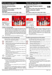
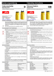
Gerätesteckdose mit
Schaltzustandsanzeige
Typ 1-1-84-652-010 (230V)
Typ 1-1-84-652-011 (24V)
connector with
lamp indication
Type 1-1-84-652-010 (230V)
Type 1-1-84-652-011 (24V)
D
GB
Anschluss und Inbetriebnahme sind nach dieser Bedienungsanleitung
und nur von autorisiertem Fachpersonal vorzunehmen. Die geltenden
Sicherheitsbestimmungen, Verwendungszweck und technischen Daten sind unbedingt einzuhalten.
Connection and commissioning must be carried out in accordance with
these operating Instructions and by authorized, qualified personnel only.
The valid safety regulations, intended use und technical data must be
observed.
Robert-Scheuffele GmbH&Co. KG
Keplerstraße 12-14
D-74321 Bietigheim-Bissingen
Telefon (07142) 597-0
Telefax (07142) 597-19
www.suco.de
E-Mail: [email protected]
Robert-Scheuffele GmbH & Co. KG
Keplerstraße 12-14
D-74321 Bietigheim-Bissingen
Phone (07142) 597-0
Fax (07142) 597-19
www.suco.de
e-mail: [email protected]
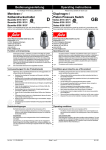
DIN EN 175301 – 803 – A
(DIN 43650 – A)
Funktion
Function
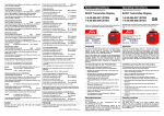
Die grüne Leuchtdiode (LED) signalisiert den Schaltzustand des
Öffnerkontaktes; die gelbe Leuchtdiode entsprechend für den
Schließerkontakt. Vor Erreichen des Schaltpunktes leuchtet die
grüne Leuchtdiode. Wird der Schaltpunkt überschritten, schaltet
die grüne Leuchtdiode aus und die gelbe Leuchtdiode ein.
Technische Daten
Betriebsspannung:
1-1-84-652-010
1-1-84-652-011
230 V AC/DC
± 20%
24 V AC/DC
± 20%
Rated operating
voltage:
1-1-84-652-010
1-1-84-652-011
230 V AC/DC
± 20%
24 V AC/DC
± 20%
Rated operating
current:
4A
bis 1,5 mm² (AWG 16)
C – VDE 0110
Pg 11
6 – 11 mm
transparente Polyamide
PA + GF 30
CuZn (Ag)
Schaltbild
1-1-84-628-007_e.doc
The green LED signalizes the behaviour of the N.C.-contact and the
yellow LED the behaviour of the N.O.-contact. In the rest position
(no pressure) the Green LED illuminates. When the switch point is
reached the green LED turns off and the yellow LED illuminates.
Technical data
Bemessungsstrom:
Anschlussquerschnitt
(Anschluss mit Adernendhülsen):
Isolierklasse:
Kabelverschraubung:
Klemmbereich:
Werkstoffe:
Gehäuse:
Isolierkörper:
Gabelkontakt:
DIN EN 175301 – 803 – A
( DIN 43650 – A)
lead-cross section
(with wire-end sleeve):
Insulation class:
cable screw coupling:
cable size:
Materials:
Housing:
Terminal board:
Contacts:
4A
maximum 1,5 mm² (AWG 16)
C – VDE 0110
Pg 11
6 – 11 mm
translucent polyamide
PA + GF 30
CuZn (Ag)
circuit diagram
Stand: 08.02.06
Seite 1 von 1 1-1-84-628-007_e.doc
State: 08.02.06
Page 1 of 1