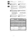
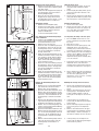
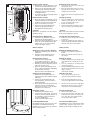
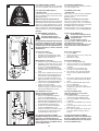
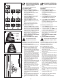
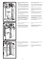
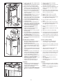
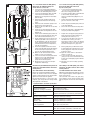
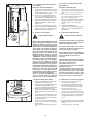
1
Bedienungsanleitung
Operating Instructions
iDOME
Vorwort
Der iDOME ist nach dem neuesten Stand der
Technik gebaut und betriebssicher. Es können
jedoch von dem iDOME Gefahren ausgehen, wenn
er nicht von geschulten oder eingewiesenen
Personen oder zu nicht bestimmungsgemässem
Gebrauch eingesetzt wird. Deshalb müssen von
jeder Person, die mit der Aufstellung, Inbetriebnahme, Bedienung, Wartung und Reparatur des
Gerätes beauftragt ist, die Bedienungsanleitung
und besonders die Sicherheitshinweise gelesen
und verstanden werden. Lassen Sie sich bzw. Ihr
Personal unbedingt vor dem ersten Einsatz des
Gerätes vom Fachberater unterweisen.
Sollten wider Erwarten an Ihrem Gerät technische
Defekte auftreten, wenden Sie sich bitte an die
Kundendienststelle oder Ihren Händler.
Forward
The iDOME is built with state-of-the-art technology and is safe to operate.
However, there is a risk of danger if the unit is
operated by people who have not been properly
instructed or trained in its use or in a way other
than that for which was intended. Therefore all
persons concerned with the assembly, installation, operation, maintenance and repair of the unit
must first read and understand the operating
instructions and especially the safety instructions.
Ensure that you and your staff are instructed by
a specialist before the unit is used for the first
time.
In the unlikely event of a technical fault please
contact our Customer Service or your dealer.
INHALTSVERZEICHNIS ............ SEITE
TABLE OF CONTENTS .............. PAGE
1
1.1
1.2
1.3
1.4
1.5
1.6
1.7
1.8
1
1.1
1.2
1.3
1.4
1.5
1.6
1.7
1.8
SICHERHEITSHINWEISE ................ 4-5
Vor der Inbetriebnahme .......................... 4
Erstinbetriebnahme des Gerätes ............. 4
Gefahrenquellen ...................................... 4
Bestimmungsgemässe Verwendung ....... 5
Produkthaftung ....................................... 5
Verhalten im Notfall ................................ 5
Erklärung der Gefahrensymbole ............. 5
Aufenthaltsort des Gerätebenutzers ........ 5
NOTES ON SAFETY ....................... 4-5
Before initial operation ............................. 4
Using the unit for the first time ................ 4
Safety warning ......................................... 4
Proper use ................................................ 5
Product liability ........................................ 5
What to do in an emergency .................... 5
Explanation of danger symbols ................ 5
Position of the user .................................. 5
ANGABEN FÜR DEN BENUTZER
INFORMATION FOR THE USER
2
2.1
2.2
2.3
2.3.1
2.3.2
2.3.3
2.3.4
2.3.5
2.3.6
2.3.7
2.3.8
2.4.
2
2.1
2.2
2.3
2.3.1
2.3.2
2.3.3
2.3.4
2.3.5
2.3.6
2.3.7
2.3.8
2.4.
BEDIENUNG ............................. 6-10
Ausstattung - Neues und Bewährtes ....... 6
Vorbereitung ........................................... 7
Starten .................................................... 7
Starten im Münzbetrieb ........................... 7
Starten im Privatbetrieb .......................... 7
Körperlüfter ............................................. 8
Kopflüfter ................................................ 8
Audio (Option) ..................................... 8-9
BREEZE (Option) ..................................... 9
AROMA (Option) ..................................... 9
Störungsanzeigen ................................... 9
Reinigen der Panelscheibe .................... 10
OPERATION .............................. 6-10
Equipment - New and proven ................... 6
Preparation ............................................... 7
Starting .................................................... 7
Starting in coinbox operation ................... 7
Starting in private operation .................... 7
Body fan ................................................... 8
Head end fan ............................................ 8
Audio (Optinal) ..................................... 8-9
BREEZE (Optinal) ..................................... 9
AROMA (Optinal) ...................................... 9
Fault indicators ......................................... 9
Cleaning the acrylic panel ...................... 10
ANGABEN FÜR DEN BETREIBER
INFORMATION FOR THE OPERATOR
3
3.1
INBETRIEBNAHME .................... 10-13
Wichtige Information! ........................... 10
Unbedingt lesen!
3.2
Vor der Inbetriebnahme ........................ 10
3.3
Erstinbetriebnahme des Gerätes ........... 11
3.3.1 Festlegen .......................................... 11-12
Münz-/ Privatbetrieb
3.4. BREEZE-Behälter anschliessen ............ 12
3.4.1 BREEZE-Leitungen entlüften ................. 13
3.4.2 AROMA-Flasche anschliessen ............... 13
3.5
Audio System ........................................ 13
3.6
Störmeldungen ..................................... 13
3
3.1
4
REINIGEN-WICHTIGE INFOR- ....... 14-15
MATION FÜR DEN BETREIBER
4
CLEANING – IMPORTANT ............ 14-15
INFORMATION FOR THE OPERATOR
5
KNOW HOW FÜR ...................... 16-19
DEN BETREIBER
Service-Modul (Betriebsstunden, ......... 16
Fehlermeldung)
Service-Modul ....................................... 16
Bedienung des Service-Moduls ............ 16
Programme des Service-Moduls ..... 17-18
Das Service-Modul auf einen Blick ....... 19
Voreingestellte Wartungsintervalle ....... 18
Übersicht über mögliche ....................... 18
Einstellungen
5
IMPORTANT INFORMATION ........ 16-20
FOR THE OPERATOR
Service module ...................................... 16
(Operating hours, error messages)
Service module ...................................... 16
Use of the service module ..................... 16
Programs of the service module ...... 17-18
The service at a glance ........................... 20
Preset service intervals .......................... 18
Overview of ............................................ 18
Possible Settings
5.1
5.1.1
5.1.2
5.1.3
5.2
5.2.1
2
COMMISSIONING ...................... 10-13
Important information! .......................... 10
To be read by everyone!
3.2
Before initial operation ........................... 10
3.3
Using the unit for the first time .............. 11
3.3.1 Specifying coin- ............................... 11-12
operated/private operation
3.4. Connecting the BREEZE tank ................. 12
3.4.1 Bleeding the BREEZE lines ..................... 13
3.4.2 Connecting AROMA bottle ..................... 13
3.5
Audiosystem .......................................... 13
3.6
Error messages ...................................... 13
5.1
5.1.1
5.1.2
5.1.3
5.2
5.2.1
INHALTSVERZEICHNIS ............ SEITE
TABLE OF CONTENTS .............. PAGE
6
6
6.1
6.1.1
6.2
6.3
6.3.1
6.3.2
6.4
6.4.1
6.4.2
6.5
6.5.1
6.5.2
6.6
6.6.1
6.6.2
6.6.3
6.6.4
6.7.
6.7.1
7.
8.
WARTUNG UND ........................ 21-30
INSTANDHALTUNG
Auswechseln der Acrylglasscheibe ....... 21
Panelscheiben ......................................... 22
Wechsel des Power Spots ................ 22-23
Wechsel der Besonnungslampe ....... 23-24
Beleuchtung der Sichtblende .................. 24
LED Griffbeleuchtung ............................. 25
Auswechseln der Filtermatten ................ 26
Filtermatten in den Panelen .................... 26
Filtermatten Montageplatte ............... 26-27
Wartung BREEZE System ....................... 27
BREEZE-Leitungen entlüften .................. 28
Störung des BREEZE Systems ............... 28
BREEZE Behälter auswechseln ............... 28
BEEZE-Düse wechseln ............................ 28
Wichtige information zu BREEZE ...... 28-29
Sprühvorgänge BREEZE ......................... 29
auf Null setzen, BREEZE entlüften
BREEZE System entlüften ....................... 29
Wechsel der AROMA Flasche ................. 29
(Option)
Auswechseln der LED-Beleuchtung ........ 30
AROMA
TIPPS ZUR BESEITIGUNG ............ 30-31
KLEINERER MÄNGEL
ENTSORGUNG .............................. 31
6.1
6.1.1
6.2
6.3
6.3.1
6.3.2
6.4
6.4.1
6.4.2
6.5
6.5.1
6.5.2
6.6
6.6.1
6.6.2
6.6.3
6.6.4
6.7.
6.7.1
7.
8.
SERVICE AND .......................... 21-30
MAINTENANCE
Replacing acrylic panels ........................ 21
Acrylic panels ......................................... 22
Exchanging the Power Spot ............. 22-23
Exchanging the Sunlamp .................. 23-24
Lighting of the facia panel ...................... 24
LED hand rail lighting ............................. 25
Changing the filter mats ......................... 26
Filter mats in the panels ......................... 26
Filter mats Mounting plate ................ 26-27
Servicing the BREEZE system ................ 27
Bleeding the BREEZE lines ..................... 28
BREEZE-system faults ............................ 28
Replacing the BREEZE tank .................... 28
Change of BREEZE nozzle ....................... 28
Important Information to BREEZE .... 28-29
Ventilation of BREEZE system ................ 29
to zero, bleed BREEZ
Set the BREEZE spray cycles .................. 29
Changing AROMA bottle ......................... 29
(optional)
Replacing the LED illumination .............. 30
AROMA
TIPS FOR ................................ 30-31
TROUBLESHOOTING
WASTE DISPOSAL ........................ 31
ANGABEN FÜR DEN TECHNIKER UND
uwe -PROFI
INFORMATION FOR THE ENGINEER
AND uwe PERSONNEL
9
9
9.1
9.2
9.2.1
9.2.2
9.2.3
9.2.4
9.2.5
9.2.6
9.2.7
9.2.8
9.3
9.3.1
9.4
9.4.1
9.4.2
9.5
AUFSTELLEN DES ..................... 32-41
PROFI-GERÄTES
Aufstellort und Anlieferungszustand ...... 32
Aufstellung und Montage ....................... 32
Montage Boden ...................................... 32
Montage Panel 1 ..................................... 33
Montage Funktionssäule ......................... 33
Körperkühlung
Montage Panel 2 ..................................... 34
Montage der Gehäuse für ....................... 34
Vorschaltgeräte
Montage Funktionssäule ......................... 35
Montage Dachmodul .............................. 35
Montage Panel Tür ................................. 36
Anschluss der Steckverbindungen ......... 37
Geräteboden beleuchtet verbinden ......... 39
(Option)
Montage Verkleidungsteile ..................... 39
Montage des Rahmens für die ................ 39
Geräteverkleidung
Montage der Geräteverkleidung ........ 39-41
Endmontage der Anbauteile. .................. 41
9.6
9.6.1
9.6.2
9.6.3
9.1
9.2
9.2.1
9.2.2
9.2.3
9.2.4
9.2.5
9.2.6
9.2.8
9.2.9
9.3
9.3.1
9.4
9.4.1
9.4.2
9.5
OPTIONEN ............................... 41-43
Transluzente Haube mit RGB (Option) .... 42
RGB-Controller mit Fernbedienung ........ 42
Tranzluzente Haube mit .......................... 43
Beleuchtungsröhren (Option)
9.7
Anschluss der Geräteabluft ..................... 43
9.7.1 Montage Abluftschlauch (Option) .......... 43
9.6
9.6.1
9.6.2
9.6.3
10
10.1
10.2
10
10.1
10.2
TECHNISCHE DATEN ...................... 44
Abmessung und UV-Typ* ....................... 44
Abdeckung der Lampen .......................... 44
(Filterscheiben)
3
INSTALLATION OF THE ............... 32-41
PROFI UNIT
Installation site and delivery condition ... 32
Assembly and Installation ...................... 32
Assemblying the bottom ......................... 32
Assemblying Panel 1 .............................. 33
Assemblying the function column .......... 33
body cooling
Assemblying Panel 2 .............................. 34
Assembling the series ............................ 34
housings
Assembling the function column ........... 35
Assembling the roof module .................. 35
Assembling the door panel ..................... 36
Connection of plug-in connections ........ 37
Connect illuminated unit bottom ............ 39
(optional)
Assembling the housing parts ................ 39
Assembling the housing ......................... 39
frame
Assembling the housing ................... 39-41
Final assembly of the attachments ......... 41
OPTIONS ................................ 41-43
Translucent Canopy with RGB (optional) 42
RGB-Controller with remote control ....... 42
Translucent canopy with ......................... 43
illumination tubes (optinal)
9.7
Connecting the Outgoing Air Unit ........... 43
9.7.1 Mounting of the exhaust hose (optional) 43
TECHNICAL DATA .......................... 44
Dimensions and UV type* ...................... 44
Lamp covers ........................................... 44
(filter discs)
1 SICHERHEITSHINWEISE
1 NOTES ON SAFETY
1.1 Vor der Inbetriebnahme
Die Sicherheitshinweise und die Bedienungsanleitung müssen vor der Aufstellung und Inbetriebnahme aufmerksam gelesen und beachtet werden. Halten Sie unbedingt die Anforderung von uwe
bzw. der Normgeber ein.
1.1 Before initial operation
The safety warnings and operating instructions
must be read carefully and observed before
installation and initial operation. The requirements
of uwe and the other manufacturers and standards
organisations must be strictly adhered to.
1.2 Erstinbetriebnahme des Gerätes
Vor jeder Inbetriebnahme sind die örtlichen Sicherheitsbestimmungen, sowie die Sicherheitshinweise einzuhalten.
1.2 Using the unit for the first time
Before each initial operation all local safety
regulations and safety requirements must be
observed.
1.3 Gefahrenquellen
Warnung!
Ultraviolettstrahlung der Sonne oder UV-Geräten
können Augen- oder Hautschäden, wie Hautalterung und möglicherweise Hautkrebs hervorrufen. Diese biologischen Wirkungen sind von der
Art und Menge der Besonnung und von der Hautempfindlichkeit der einzelnen Person abhängig.
Die Haut kann nach überhöhter Besonnung Sonnenbrand zeigen. Übermässig häufig wiederholte
Ultraviolettbestrahlung mit Sonnenlicht oder UVGeräten kann zu frühzeitiger Alterung der Haut und
auch zu einem erhöhten Risiko von Hauttumoren
führen. Das ungeschützte Auge kann sich auf der
Oberfläche entzünden und in bestimmten Fällen
kann übermässige Besonnung die Netzhaut beschädigen. Nach ungeschützten Besonnungen
kann sich Grauer Star bilden. In Fällen besonderer
UV-Empfindlichkeit des Einzelnen oder dann, wenn
gleichzeitig bestimmte Medikamente oder Kosmetika verwendet werden, ist besondere Vorsicht
geboten.
1.3 Safety warning
Warning!
Exposure to ultraviolet light from either the sun or
a solarium can cause damage to the eyes and skin
such as premature ageing of the skin or even skin
cancer. These biological effects depend on the type
and amount of exposure to ultraviolet light and on
the skin sensitivity of the individual. The skin may
burn after overexposure to ultraviolet light.
Excessive exposure to ultraviolet light from either
the sun or UV sunlamps can lead to premature
ageing of the skin and an increased risk of skin
cancer.
If the naked eye is exposed to UV light, the surface
of the eye may become inflamed.
In some cases excessive exposure can damage the
retina. Cataracts may result from unprotected
exposure.
Particular care with solarium exposure is required
where an individual is specially sensitive to UV light
or where certain medicines or cosmetics are being
used at the same time.
Warnung!
Warning!
Warnung
Warning
Deshalb unbedingt folgende Sicherheitshinweise
beachten:
Grosse Helligkeit, deshalb nicht in den Strahler
blicken.
Beim Sonnenbaden die Augen schliessen und
stets die mitgelieferte Schutzbrille tragen.
Kosmetika rechtzeitig vor der Besonnung entfernen. Keinerlei Sonnenschutzmittel verwenden.
Schmuck vor jeder Besonnung abnehmen.
Nicht mehr als eine Besonnung je Körperteil alle
zwei Tage nehmen, nicht zusätzlich am gleichen
Tag Sonnenbaden in der Natursonne.
Das Gerät darf nicht von Personen benutzt werden, die, wenn sie der Sonne ausgesetzt sind,
einen Sonnenbrand bekommen ohne zu bräunen.
Das Gerät darf nicht von Personen benutzt werden, die unter Sonnenbrand leiden.
Das Gerät darf nicht von Kindern benutzt werden.
Das Gerät darf nicht von Personen benutzt werden, die unter Hautkrebs leiden oder litten bzw.
dafür prädisponiert sind.
Empfehlungen bezüglich Besonnungszeiten und
Besonnungsintervallen liegen jedem Gerät als
Zeittafel bei.
Die empfohlenen Besonnungszeiten gelten nur
für die vom Hersteller vorgeschriebenen Lampenbestückungen.
Bei ärztlicher Behandlung oder Einnahme von
Medikamenten auf jeden Fall Ihren Arzt zu Rate
ziehen. Bestimmte Medikamente oder Kosmetika
können die Empfindlichkeit erhöhen. Benutzung
des Gerätes nur nach Befragung eines Arztes.
Bei hartnäckigen Schwellungen, wunden Stellen
oder pigmentierten Leberflecken auf der Haut,
die sich verändern, unverzüglich Ihren Arzt aufsuchen.
Lassen Sie mindestens 48 Stunden zwischen
Ihren ersten beiden Besonnungen auf dem
iDOME verstreichen.
Therefore the following safety instructions must
be strictly adhered to:
The lamps are extremely bright, therefore never
look directly at the lamps.
Close your eyes while tanning and always wear
the protective goggles provided. Remove all
cosmetics before tanning.
Do not use any type of sun protection. Remove
all jewellery before tanning. No part of the body
should be exposed to ultra-violet light more than
once during a period of 48 hours. Never sun bathe
in natural sunlight on the same day.
The equipment should not be used by any person
who easily becomes sunburnt without tanning
when exposed to the sun.
Do not use the equipment if you already have
sunburn.
The equipment must not be used by children.
The equipment must not be used by persons who
have suffered from skin cancer in the past or
anyone at high risk of skin cancer.
For recommended exposure times and frequencies, please see the recommended exposure
chart supplied with each unit. Recommended
tanning times are only valid in conjunction with
the lamps specified by the manufacturer.
If you are currently undergoing treatment or
taking medication consult your doctor. Some
medications and cosmetics may increase
sensitivity to UV exposure.
Consult your doctor before using the equipment.
Contact your doctor immediately if you have
persistent swellings, sores or pigmented moles
on your skin that have changed.
Make sure there are at least 48 hours between
your first and second tanning sessions on the
iDOME.
4
1.4 Bestimmungsgemässe Verwendung
Alle Geräte sind ausschliesslich bestimmt zur Besonnung von Personen im Innenbereich von Gebäuden im kommerziellen Bereich. Das Gerät nur
in nicht explosionsgefährdeten Bereichen und in
Trockenräumen betreiben. Die Räume müssen über
eine gute Be- und Entlüftung verfügen. Wird das
Gerät in einem Sonnenstudio betrieben, ist sowohl
am Gerät als auch im Raum auf äusserste Hygiene
zu achten. Jeder darüber hinaus gehende Gebrauch
gilt als nicht bestimmungsgemäss. Für hieraus resultierende Schäden haftet der Hersteller nicht; das
Risiko hierfür trägt allein der Benutzer. Zur bestimmungsgemässen Verwendung gehört auch die
Einhaltung der vom Hersteller vorgeschriebenen
Betriebs-, Wartungs-, und Instandhaltungsbedingungen. Wartungs- und Reparaturarbeit und
dergleichen dürfen nur vom uwe Kundendienst
oder von uwe ermächtigten Personen durchgeführt
werden. Die Geräte dürfen nur von Personen genutzt werden, die hiermit vertraut und über die
Gefahren unterrichtet sind. Die einschlägigen Unfallverhütungsvorschriften, sowie die sonstigen
allgemein anerkannten sicherheitstechnischen,
arbeitsmedizinischen Regeln sind einzuhalten.
Eigenmächtige Veränderungen an den Geräten
schliessen eine Haftung des Herstellers für daraus
resultierende Schäden aus. Dies gilt insbesondere
für Schäden, die auf nicht von uwe freigegebene
Lampen- bzw. Filterscheibenbestückungen zurückzuführen sind.
1.4 Proper Use
All units are intended exclusively for indoor
tanning of people and for commercial use.
The unit must only be used in dry surroundings
where there is no danger of explosion.
The area must be well ventilated.
If operated in a tanning salon, the surroundings
and solarium equipment itself must be kept
hygienic and always clean.
Using the equipment for any other than the
intended purpose will be regarded as misuse.
In this case, the manufacturer will accept no liability
for any damage which may arise.
All liabilities will be the responsibility of the user.
Proper use also includes observance of the
operating, servicing, and maintenance conditions
specified by the manufacturer.
Servicing and repair work and the like may only
be carried out by uwe Customer Service or persons
appointed by them.
The units may only be operated by those who are
familiar with them and who have been instructed
about the possible dangers. Appropriate accident
prevention measures and other generally accepted
rules regarding safety and industrial medicine must
be observed.
Unauthorized changes to the units exclude the
liability of the manufacturer for any resulting injury.
This applies in particular to any injury which may
result from the use of lamps and/or filter discs not
authorized by uwe.
1.5 Produkthaftung
Der Benutzer wird ausdrücklich darauf hingewiesen, dass das Gerät ausschliesslich bestimmungsgemäss eingesetzt werden darf. Für den Fall,
dass das Gerät nicht bestimmungsgemäss eingesetzt wird, geschieht dies in der alleinigen Verantwortung des Anwenders.
Jegliche Haftung des Herstellers entfällt somit.
1.5 Product liability
The attention of the user is drawn explicitly to the
fact that the unit may only be used for the intended
purpose.
If the unit is used for a purpose other than that
intended, all responsibility falls to the user.
All liability of the manufacturer is no longer
applicable.
1.6 Verhalten im Notfall
Netzstecker ziehen, bzw. Geräte
durch Hauptschalter oder Sicherungen spannungsfrei schalten und
Warnung gegen unbefugtes Wiedereinschalten sichern.
1.6 What to do in an emergency
Remove the mains plug or
disconnect the power via the main
switch or fuses. Ensure that the unit
Warning cannot be switched on again by
unauthorized persons.
1.7 Erklärung der Gefahrensymbole
In dieser Bedienungsanleitung haben wir alle
Stellen, die Ihre Sicherheit, Hinweise und Tipps
betreffen, mit folgenden Zeichen versehen.
Geben Sie alle Sicherheitsanweisungen auch an
andere Benutzer weiter.
1.7 Explanation of danger symbols
All sections of these operating instructions
relating to your safety are marked with this
symbol.
Please also pass on all information regarding
safety to other users.
Dieses Symbol bedeutet eine möglicherweise drohende Gefahr für das
Warnung Leben und die Gesundheit von
Personen.
Das Nichtbeachten dieser Hinweise hat schwere
gesundheitsschädliche Auswirkungen zur Folge,
bis hin zu lebensgefährlichen Verletzungen.
This symbol signifies an imminent
danger to the life or health of
persons.
Wichtig!
Dieses Symbol gibt wichtige
Hinweise für den sachgerechten
Umgang mit der Maschine.
Das Nichtbeachten dieser Hinweise kann zu
Störungen an dem Gerät oder in der Umgebung
führen.
Funktion
Unter diesem Symbol erhalten Sie
Anwendungs-Tipps und besonders
nützliche Informationen.
Warning
The consequences of non-compliance with
these notices can have a serious harmful effect
on health, and may extend to fatal injury.
This symbol provides important
information for the proper handling
Important! of the units.
Non-compliance with these instructions can
cause faults on the machine or in the vicinity of
it.
Function
Next to this symbol you will find tips
on how to use the equipment and
other useful information.
Sie helfen Ihnen, alle Funktionen an Ihrem Gerät optimal zu nutzen.
They will help you to make optimal use of the
functions on your equipment.
1.8 Aufenthaltsort des Gerätebenutzers.
In dem Gerät.
1.8 Position of the user.
In the unit.
5
ANGABEN FÜR DAS
STUDIOPERSONAL
2 BEDIENUNG
INFORMATION FOR THE TANNING
SALON PERSONNEL
2 OPERATION
2.1 Ausstattungen - Neues und Bewährtes
2.1 Equipment - New and proven
Wichtige Informationen!
Unbedingt lesen!
Important Information! To be read
by everyone!
Warnung
Warning
Nicht alle Gerätetypen verfügen über die hier
aufgeführten Ausstattungsmodule und somit
über alle Bedienmöglichkeiten.
1. Entnehmen Sie die Ausstattung Ihres
Gerätes dem Katalog.
2. Beachten Sie die für Ihr Gerät geltenden
Hinweise.
3. Geben Sie alle Informationen an den
Benutzer weiter.
Not every model is equipped with all of the
modules described here and therefore all
options.
1. Check the brochure for the features of your
unit.
2. Please observe the instructions which
apply to your unit.
3. Please pass on all information to the user.
INTERAKTIVE BEDIENUNG
Sie können die Intensitäten der Kühlung für den
Körperbereich und den Gesichtsbereich getrennt
regulieren.
INTERACTIVE OPERATION
You can regulate intensity the cooling for your
body and face separately.
KÖRPERKÜHLUNG
Es befinden sich im Säulensegment und in der
Funktionssäule Luftöffnungen, die Kühlluft direkt
über Gesicht und Körper führen.
AIR JET BODY COOLING
An air vent is provided in the column segment
and in the function column which allows cool air
to be directed over the upper part of the body.
LÜFTER
Die Lüfter laufen nach Abschalten des Gerätes
noch 2 Minuten (Werkseinstellung) weiter, um
das Gerät abzukühlen.
FAN
The fans continue to run for about 2 minutes
(factory setting) after switching off the unit in
order to cool it down.
POWERSPOT (Option*)
Es befinden sich im Dach 3 POWERSPOTS für
eine gezielte Bräunung.
POWER SPOT (Optional*)
There are three POWER SPOTS in the roof for
focused tanning.
BREEZE (Option*)
In der Funktionssäule befindet sich eine Düse,
aus der auf Wunsch ein feiner Sprühnebel aus
destilliertem, keimfreiem Wasser in den Besonnungsinnenraum gesprüht werden kann.
BREEZE (Optional*)
There is a nozzle in the function column from
which a fine atomised spray of distilled, sterilised
water can be sprayed into the tanning area on
demand.
AROMA (Option*)
Im Säulensegment des Gerätes befindet sich ein
Aroma-Modul. Bei Betätigung der Taste für das
Aroma-Modul wird 30 Sekunden lang der
Besonnungsraum beduftet. In dieser Zeit leuchtet
die Abdeckung des Aroma-Moduls.
AROMA (Optional*)
There is an aroma module in the column segment
of the unit. When the aroma module button is
pressed, fragrance is sprayed into the tanning
area for 30 seconds. During this time the LED in
the aroma button lights up.
SERVICE MODUL
Im Service-Modul können Sie die Betriebsstunden getrennt nach Gesamtbetriebsstunden Solarium und Betriebsstunden, ND-Lampen und
POWERSPOT abrufen. Im Service-Modul werden
Fehlermeldungen angezeigt. Das Service-Modul
erleichtert die Wartung und Überprüfung der
Verschleissteile auf Alterung (Kap. 5).
SERVICE MODULE
The service module allows you to monitor the
operating hours according to the total operating
hours of the solarium, the operating time of the
ND lamps and POWER SPOT. The service module
displays error messages.
The service module facilitates maintenance and
inspection of parts for wear (see Ch. 5).
AUDIOSYSTEM (Option*)
Das Gerät kann an ein externes Audiosystem
angeschlossen werden.
AUDIO SYSTEM (Optinal*)
The unit may be connected to an external sound
system.
HANDYANSCHLUSS (Option*)
Das Gerät verfügt über einen Anschluss für Ihr
Handy, damit Sie Ihre eigene Musik hören können.
CONNECTION TO CELL PHONE (Option*)
The bed has a connection for your cell phone
with which you can hear your own music.
LAUTSPRECHER (Option*)
Auf Wunsch können Sie Ihr Gerät mit 2 Lautsprechern ausstatten, so dass Sie während der
Besonnung die zentral eingespielte Unterhaltung
geniessen können.
LOUDSPEAKER (Optional*)
If you prefer, you can equip your solarium with
two speakers allowing you to enjoy the music
played on the central sound system while you
tan.
6
1
2.2 Vorbereitung
1. Stellen Sie sich in die Mitte des iDOMES.
2. Schließen Sie den iDOME mit Hilfe des
Handgriffs.
2.2 Preparation
1. Stand in the center of the iDOME.
2. Use the hand rail to close the iDOME.
2.3 Starten
Beachten Sie die Zeittafel.
Die für Ihren Hauttyp empfohlene
Besonnungszeit nicht überschreiten. Sonnenbrand unbedingt
Warnung vermeiden.
Nie bei einem bestehenden
Sonnenbrand besonnen.
Bedingt durch Ihren Hauttyp
können Sie eine bestimmte
Endbräune erreichen. Diese kann
durch Gebrauch eines Solariums
nicht weiter vertieft, sondern nur
erhalten werden.
Beim Sonnenbaden die Augen
schliessen und stets die mitgelieferte Schutzbrille tragen.
An den Augenlinsen operierte
Personen müssen eine Schutzbrille
tragen.
2.3 Starting
Observe the tanning schedule.
Do not exceed the recommended
tanning times for your skin type.
Avoid sunburn.
Warning Never exposure yourself to
ultraviolet light if you already have
a sunburn.
Your final tan (when your skin does
not darken any more) depends on
your skin type.
Your tan cannot be intensified by
using a solarium but only
maintained by it.
Close your eyes while tanning and
always wear the protective goggles
provided.
People who have undergone
surgery to their eye lenses must
wear protective goggles.
Bedien- und Anzeigeelemente:
•
[START] - Taste (1/1)
•
[STOP] - Taste (1/2)
•
Display (1/3)
Operating and display elements:
•
[START] button (1/1)
•
[STOP] button (1/2)
•
Display (1/3)
2.3.1 Starten im Münzbetrieb
1. Werfen Sie Münzen bzw. Chips in den Münzzeitgeber ein.
Das Gerät schaltet abhängig von der verwendeten Zentralsteuerung bzw. vom
Münzzeitgeber nach Ablauf der Vorlaufzeit
automatisch ein.
2. Möchten Sie das Gerät vor Ablauf der Vorlaufzeit aktivieren, drücken Sie die STARTTaste (1/1) (Frühstart).
3. Möchten Sie das Gerät vor der eingestellten
Zeit abschalten, drücken Sie die STOP-Taste
(1/2).
Die Besonnungszeit läuft während dieser
Unterbrechung weiter, d. h. die blinkende
Display-Anzeige (1/3) zählt die Zeit weiter
hoch.
2.3.1 Starting by inserting a coin
1. Insert coins or chips into the coin meter.
2.3.2 Starten im Privatbetrieb
1. Betätigen Sie die START-Taste (1/1) auf der
Bedien-Einheit.
2. Erhöhen Sie die Besonnungszeit in Minutensprüngen durch mehrmaliges Betätigen der
START-Taste (1/1).
3. Reduzieren Sie die Besonnungszeit in
Minutensprüngen durch mehrmaliges
Betätigen der STOP-Taste (1/2).
Die Einstellung der gewünschten Besonnungszeit muss innerhalb von 20 Sekunden erfolgen. Die Besonnung beginnt
5 Sekunden nach der erstmaligen Betätigung der START-Taste (1/1).
4. Möchten Sie das Gerät vor der eingestellten
Zeit abschalten, so betätigen Sie die STOPTaste (1/2). Das blinkende Display zeigt die
verbleibende Besonnungszeit an.
5. Betätigen Sie START-Taste (1/1) erneut, wird
die Besonnung fortgesetzt.
Sie haben maximal 60 Minuten Zeit, die
Besonnung fortzusetzen.Mit der STOPTaste (1/2) können Sie die Besonnung
jederzeit unterbrechen.
6. Betätigen Sie erneut die STOP-Taste (1/2),
wird die Besonnung ganz unterbrochen und
die Display-Anzeige (1/3) wird auf Null
gesetzt.
2.3.2 Starting in private operation
1. Actuate START-button (1/1) on the operating
unit.
2. Increase the tanning time in one-minute
increments by repeatedly actuating STARTbutton (1/1).
3. Reduce the tanning time in one-minute
increments by repeatedly actuating STOPbutton (1/2).
The desired tanning time must be set
within 20 seconds.
Tanning begins 5 seconds following the
initial actuation of START-button (1/1).
7
The unit starts automatically after the
warming-up period, depending on whether
central control desk or coin timer is used.
2.
3.
If you want to start the unit before the end
of the warming-up period, press the STARTbutton (1/1) (Early start).
You can interrupt the tanning session by
pressing the STOP button (1/2).
The tanning time continues during this
interruption, i.e. the display (1/3)
continues to count.
4.
5.
6.
If you would like to switch off the unit before
the set time has passed, actuate the STOPbutton (1/2).
The flashing display shows the remaining
tanning time.
Actuate START-button (1/1) again to
continue the tanning session.
You have up to 60 minutes to continue
the tanning session.
With STOP-button (1/2), you can interrupt
the tanning session at any time.
Actuate STOP-button (1/2) again and the
tanning session is completely interrupted
and the display (1/3) reset to zero.
2
2.3.3 Kopflüfter
2.3.3 Head end fan
Bedien- und Anzeigeelemente
•
[+] - Taste (2/1)
•
[-] - Taste (2/3)
•
LED (2/2)
Operating and display elements
•
[+] button (2/1)
•
[-] button (3/3)
•
LED (2/2)
Die Tasten steuern die Kühlluftzufuhr über den
Kopf. Durch Betätigen von [+] (2/1) wird die
Intensität der Kühlluftzufuhr gesteigert, durch
Betätigen von [-] (2/3) wird die Intensität verringert.
Sie können zwischen 3 Stufen wählen. Die 5 LED
(2/2) werden entsprechend der 3 Stufen eingeschaltet.
Möchten Sie die Kopflüftung ganz abschalten,
betätigen Sie bei Stufe 1 die [-] (2/3) Taste für
drei Sekunden.
Bei einem erneuten Start der Besonnung, wird
die vorher eingestellte Stufe beibehalten.
War die Kopflüftung ausgeschaltet, läuft das Gerät
auf Stufe 2 an.
The buttons control the infeed of cooling air over
the head. Actuate [+] (2/1) to increase the
intensity of the cooling air infeed; actuate [-]
(2/3)to reduce the intensity.
You can select from 3 levels. The 5 LEDs (2/2)
are switched on appropriately for the 3 levels.
If you would like to completely switch off head
cooling, actuate the [-] (2/3) button for three
seconds while on level 1.
The previously set level is retained when restarting tanning.
If head cooling was switched off, the unit starts
on level 2.
2.3.4 Körperlüfter
2.3.4 Body fan
Bedien- und Anzeigeelemente
•
[+] - Taste (2/4)
•
[-] - Taste (2/6)
•
LED (2/5)
Operating and display elements
•
[+] button (2/4)
•
[-] button (2/6)
•
LED (2/5)
Die Tasten steuern die Kühlluftzufuhr über den
Körper. Durch Betätigen von [+] (2/4) wird die
Intensität der Kühlluftzufuhr gesteigert, durch
Betätigen von [-] (2/6) wird die Intensität verringert.
Sie können zwischen 3 Stufen wählen.
Die 5 LED werden entsprechend der 3 Stufen
eingeschaltet.
Möchten Sie die Körperlüftung ganz abschalten,
betätigen Sie bei Stufe 1 die [-] Taste (2/6) für
drei Sekunden.
Bei einem erneuten Start der Besonnung, wird
die vorher eingestellte Stufe beibehalten.
War die Körperlüftung ausgeschaltet, läuft das
Gerät auf Stufe 2 an.
The buttons control the infee (2/4) to increase
the intensity of the cooling air infeed; actuate [-]
(2/6)to reduce the intensity.
You can select from 3 levels.
The 5 LEDs are switched on appropriately for the
3 levels.
If you would like to completely switch off body
cooling, actuate the [-] (2/6) button for three
seconds while on level 1.
The previously set level is retained when restarting tanning.
If body cooling was switched
off, the unit starts on level 2.
2.3.5 AUDIO (OPTION)
2.3.5 AUDIO (OPTIONAL)
• Programmwahl
Bedienelemente
•
Taste (2/9)
•
Taste (2/10)
• Program selection
Operating elements
•
button (2/9)
•
button (2/10)
Wählen Sie über (2/9) und (2/10) aus den eingespielten Unterhaltungsprogrammen aus.
Use (2/9) and (2/10) to select from the entertainment programs which are fed into the unit.
• Lautstärke
Bedienelemente
•
[+] - Taste (2/7)
•
[-] - Taste (2/8)
• Volume
Operating elements
•
[+] button (2/7)
•
[-] button (2/8)
Mit den beiden Tasten können Sie die Lautstärke
der eingespielten Unterhaltung regeln. Betätigen
Sie [+] (2/7) wird die Lautstärke gesteigert, betätigen Sie [-] (2/8) wird die Lautstärke verringert.
With the two buttons, you can control the volume
of the entertainment being fed into the unit.
Actuate [+] (2/7) to increase the volume; actuate
[-] (2/8) to decrease the volume.
8
3
Handyanschluss
Bedienelemente
•
Anschlussbuchse (3/1)
•
Handyschale (3/2)
Connection to cell phone
Operating elements
•
Socket (3/1)
•
Cell phone holder (3/2)
Stecken Sie den Stecker des Handys in die Buchse
(3/1). Die zentral eingespielte Unterhaltung wird
automatisch unterbrochen und Sie können Ihre
eigene Unterhaltung hören.
Plug the cell phone jack into the socket (3/1).
Thus the music played on the central sound
system is interrupted and you can listen to your
own music.
2.3.6 BREEZE (Option*)
2.3.6 BREEZE (Optional*)
Bedien- und Anzeigeelemente
•
Taste BREEZE (3/5)
•
LED (3/6)
Operating and display elements
•
BREEZE button (3/5)
•
LED (3/6)
Betätigen Sie die Taste (3/5) mit dem Symbol für
BREEZE, es wird ein feiner Sprühnebel aus
destilliertem Wasser aus der Düse (3/3) oberhalb
des Körperlüfters (3/4) auf den Körper und das
Gesicht gesprüht.
Die LED (3/6) leuchtet während eines Sprühvorganges. Nach ca. 40 Sekunden (Sperrzeit),
können Sie BREEZE erneut aktivieren.
Press the button (3/5) with the symbol for
BREEZE for a fine mist of distilled water to be
spray from the nozzle (3/3) located above the
body fan (3/4) onto the body and face.
2.3.7 AROMA (Option*)
2.3.7 AROMA (Optional*)
Bedien- und Anzeigeelemente
•
Taste AROMA (4/1)
•
LED (4/2)
Operating and display elements
•
Button AROMA (4/1)
•
LED (4/2)
1.
1.
Press the button above the Aroma module.
The button is illuminated by LED.
2.
The Aroma module is active for 10 seconds.
The LED illumination is on during this time.
3.
After approx. 30 seconds (pause time)
AROMA can be reactivated.
2.
3.
4
Betätigen Sie die Drucktaste über dem
Aromamodul, das Feld des Aromamoduls
wird von LED-Lampen beleuchtet.
10 Sekunden lang strömt nun der AROMADuft in den Besonnungsraum, nach Ablauf
dieser Zeit erlöschen die LED-Lampen die
das Aromamodul beleuchten.
Nach ca. 30 Sekunden (Sperrzeit), können
Sie AROMA erneut aktivieren.
The LED (3/6) lights up during the spray cycle.
After approx. 40 seconds (pause time) BREEZE
can be reactivate.
2.3.8 Störungsanzeigen
Bei Erreichen der voreingestellten Wartungsintervalle folgender Funktionen leuchtet der rechte
Dezimalpunkt (5/1):
• BREEZE
• Power Spot
• ND-Lampen
2.3.8 Fault indicators
When the preset service intervals have been
reached for the following functions, the right
decimal point illuminates (5/1):
• BREEZE
• Power Spot
• LP lamps
BREEZE weist folgende Besonderheit auf: Nach
längerer Überschreitung des voreingestellten
Wartungsintervalls wechselt die Dauerleuchtanzeige des rechten Dezimalpunktes zu einem
Blinken und die BREEZE Funktion wird deaktiviert.
BREEZE has the following special feature: If the
preset service interval is exceeded by a relatively
long period of time, the continuously illuminated
right decimal point begins to flash and the
BREEZE function is deactivated.
Please inform the salon personnel.
Benachrichtigen Sie bitte das
Studiopersonal.
Funktion
Function
5
9
6
2.4 Reinigen der Bodenplatte, der Acrylglasscheibe und der Haltegriffe
2.4 Cleaning the floor plate, the acrylic sheet
panel and the handles.
Die Bodenplatte, die Acrylglasscheiben und die Haltegriffe der Panele
müssen nach jeder Besonnung desWarnung infiziert und gereinigt werden.
The floor plate, the acrylic sheet
panel and the handles of the panel
must be disinfected and cleaned
Warning following each tanning session.
Ausschliesslich uwe Reiniger
„PICCOBELLO“ verwenden!
Only use uwe “PICOBELLO”
cleaning agent!
Immer auf äusserste Hygiene
achten.
Always pay great attention to
hygiene.
uwe Reiniger und andere Reinigungsmittel nicht in die Augen
sprühen.
Keep uwe cleaning agent or other
cleaning agents out of your eyes.
Nicht in offene Flammen sprühen.
Do not drink.
Nicht trinken.
Keep out of reach of children.
Darf nicht in die Hände von Kindern
gelangen.
Follow the manufacturer’s
instructions for the cleaning agent
and take account of the specified
activation time.
Do not spray near an open flame.
Reinigungsmittel nach Gebrauchsanweisung verwenden und die vom
Hersteller dafür angegebene
Einwirkzeit einhalten.
Never pour liquid directly onto the
unit to avoid the risk of moisture
getting inside and affecting the
electrical equipment.
Keine Flüssigkeit über das Gerät
schütten, damit keine Feuchtigkeit
in die Elektrik gelangen kann.
Reinigen der Bodenplatte, der Acrylglasscheiben und der Haltegriffe der Panele
1. Reinigen Sie nach jeder Besonnung die
Bodenplatte, die Acrylglasscheiben und die
Haltegriffe der Panele mit dem uwe Reiniger
PICCOBELLO oder dem Paletti Hydro Vlies.
2. Sprühen Sie bei Verwendung des uwe
Reinigers PICCOBELLO diesen auf die
Panelscheibe und lassen ihn ca. 1 Minute
einwirken.
3. Trocknen Sie immer mit einem sauberen
Tuch nach.
Cleaning the floor plate, the acrylic sheet and
the panel handles
1. Clean the floor plate, the acrylic sheet and
the panel handles after each tanning
session using uwe PICCOBELLO cleaner
or Paletti Hydro fleece.
2. When using uwe PICCOBELLO cleaner,
spray it onto the acrylic sheet bed and allow
it to act for approx. 1 minute.
3. Always dry the panel afterwards with a clean
cloth.
ANGABEN FÜR DEN BETREIBER
INFORMATION FOR THE USER
3
3
Inbetriebnahme
3.1 Wichtige Information! Unbedingt lesen!
Keine mangelhaften Besonnungsgeräte in Betrieb nehmen.
Achten Sie auf die höchstzulässige
Warnung Raumtemperatur von maximal 35°C,
sonst besteht die Gefahr, dass sich
das Gerät zu stark erhitzt.
Auf die hygienischen Anforderungen
achten.
Schutzbrillen bereitstellen und auf
das Tragen derselben achten.
Auf Einhaltung der vom Hauttyp abhängigen Besonnungsdauer hinweisen.
Montage- und Bedienungsanleitung
bereit halten.
Sicherheitshinweise und Zeittafel im
Besonnungsraum deutlich sichtbar
anbringen.
Gerät nur in geschlossenem Zustand
für längere Zeit betreiben.
3.2 Vor der Inbetriebnahme
Die Sicherheitshinweise und Bedienungsanleitung müssen vor dem Aufstellen und der Inbetriebnahme aufmerksam gelesen, beachtet und
verstanden werden.
10
Initial operation
3.1 Important Information!
Warning
To be read by everyone! Never
switch on a defective sun bed.
Ensure the maximum permissible
room temperature (35°C) is not exceeded, otherwise the unit may overheat.
Observe the requirements with regard to hygiene.
Be sure to provide protective goggles
and ensure that they are worn.
Point out that the permitted tanning
time depends on the type of skin.
Make sure the assembly and operating instructions are always available.
Be sure the safety instructions and
tanning schedules are clearly visible in the tanning cubicle.
Use the unit only in the closed state
for a longer period of time.
3.2 Before initial operation
Safety regulations and operating instructions
must be read carefully and taken into account
before installation and start-up.
3.3 Erstinbetriebnahme des Gerätes
Vor jeder Inbetriebnahme sind die örtlichen
Sicherheitsbestimmungen, sowie die Sicherheitshinweise einzuhalten.
Ist das Gerät komplett montiert, elektrisch angeschlossen und mit dem Münzzeitgeber bzw. der
Zentralsteuerung verbunden, kann das Gerät in
Betrieb genommen werden.
3.3 Using the unit for the first time
Before each initial operation all local safety
regulations and safety warnings must be
observed. Once the unit has been fully assembled,
connected to the power supply and coin-operated
timer or central control unit, it can be switched
on.
Die in nachfolgende Abschnitten beschriebenen
Arbeiten sind bei der Erstinbetriebnahme durchzuführen.
The tasks described in the following sections are
to be performed during the initial commissioning.
3.3.1 Festlegen Münz-/ Privatbetrieb
Das Gerät ist bei der Auslieferung ab Werk für
Münzbetrieb konfiguriert.
3.3.1 Specifying coin-operated/private
operation
The unit is configured for coin operation upon
delivery from the factory.
If the unit is to be operated privately, you must
set the unit for private operation prior to initial
start-up.
To do this, a jumper must be repositioned on the
mounting plate (behind the front apron).
Falls das Gerät im Privatbetrieb betrieben werden
soll, müssen Sie vor der Erstinbetriebnahme das
Gerät für den Privatbetrieb vorbereiten.
Dazu ist auf der Montageplatte Steuerung (hinter
dem Panel) ein Jumper umzustecken.
Warnung
7
8
Lebensgefahr! Gerät stromlos
schalten und gegen unbeabsichtigtes Wiedereinschalten sichern!
Warning
Danger to life ! De-energize the
unit and protect against accidentally being switched back on!
Bodenplatte ausbauen
1. Die Bodenplatte (7/1) ist mit 2 Stiften (7/2)
in die zwei Bohrungen (7/4), die sich in der
Querstrebe (7/3) des Metallbodens befinden,
eingesteckt.
2. Heben Sie die Bodenplatte (7/1) nach oben
ab und stellen Sie diese zur Seite.
Removing the bottom plate
1. The base plate (7/1) is plugged with two pins
(7/2) in the two holes (7/4) located in the
cross strut (7/3) of the metal bottom.
Acrylglasscheibe Panel ausbauen
1. Entriegeln Sie die sechs Drehriegel (8/4)
mit dem Innensechskantschlüssel (8/3).
2. Bewegen Sie die Panel-Acrylglasscheibe
(8/1) etwas nach links, damit diese mit ihren
Langlöchern (8/2) aus der Arretierung am
Handgriff rutscht.
3. Jetzt können Sie die Panel-Acrylglasscheibe
(8/1) nach vorne entnehmen.
4. Stellen Sie die Acrylglasscheibe zur Seite.
Remove the acrylic panel
1. Unlock the six lock bolts (8/4) with the
Allen key (8/3).
2. Move the acrylic panel (8/1) a little to the
left to allow the grooves (8/2) to slide out of
the locking device at the handle.
Besonnungslampe ausbauen
1. Drehen Sie die Besonnungslampe (8/7) in
beliebiger Richtung, bis die Kontaktstifte in
der Nut der Fassung (8/8) sichtbar sind.
2. Ziehen Sie die Lampe (8/7) heraus.
3. Bauen Sie alle Besonnungslampen aus,
damit Sie die Abdeckung der Montageplatten
ausbauen können.
Changing the sunlamp
1. Turn the sunlamp (8/7) in either direction
until the contact pins can be seen in the
groove of the lamp holder (8/8).
2. Remove the lamp (8/7).
3. Remove all sunlamps to be able to remove
the mounting board covers.
Abdeckung des Serviceschachts 1 entfernen
1. Entfernen Sie die Schrauben (8/5) der
Abdeckung (8/6) für die Montageplatten.
2. Nehmen Sie die Abdeckung ab.
Remove the service compartment cover 1
1. Remove the screws (8/5) of the mounting
board (8/6) cover.
2. Lift off the cover.
Das Gerät ist bei Auslieferung ab Werk für
Münzbetrieb konfiguriert.
Position Jumper für Münzbetrieb 1,2 Münzer
(Werkseinstellung).
Position Jumper 2,3 prvt. für Privatbetrieb.
The unit is configured for coin operation upon
delivery from the factory.
Position of jumper for coin operation 1,2 coinbox(factory setting).
Position of jumper 2,3 pvrt. for private operation.
Gerät konfigurieren für Privatbetrieb
1. Ziehen Sie den Jumper (8/9) aus Position
1,2 vom linken und mittleren Pfostenstecker
ab.
2. Stecken Sie den Jumper (8/9) in Position
2,3 auf den mittleren und rechten Pfostenstecker für Privatbetrieb.
Configuring unit for private operation
1. Pull the jumper (8/9) out of position 1,2
coinbox, from the left and center post
connectors.
2. Connect the jumper (13/3) in position 2,3
on the center and right post connectors for
private operation.
11
2.
3.
4.
Lift the bottom plate (7/1) to the top.
Now you can take out the acrylic panel (8/1)
to the front.
Put the acrylic sheet panel aside.
9
10
11
Weiteres Vorgehen
Further procedure
• Reflektor
Wischen Sie den Reflektor (9/10) mit einem
Alkohol getränkten Tuch ab.
• Reflector
Wipe off the reflector (9/10) with a cloth
moistened with alcohol.
Abdeckung des Serviceschachts 1 montieren
1. Nehmen Sie Abdeckung (9/6) für die Montageplatten.
2. Befestigen Sie die Abdeckung mit den
Schrauben (9/5) auf dem Reflector.
Mounting the cover of service compartment 1
1. Take the mounting board cover (9/6).
2. Fasten the cover with the screws (9/5) on
the reflector.
Besonnungslampe einbauen
1. Halten Sie die Besonnungslampe
(9/7) senkrecht und zwar so, dass die
Kontaktstifte senkrecht übereinander liegen.
2. Drücken Sie die Besonnungslampe in dieser
Lage in die Fassung (9/8).
3. Drehen Sie die Besonnungslampe um 90
Grad, so dass die Einkerbung im Metallring
am Lampenende oben liegt.
Bauen Sie alle Besonnungslampen ein.
Mounting the sunlamps
1. Hold the sunlamp (9/7) in vertically so that
the contact pins are vertically above each
other.
2. Press the sunlamp into the lamp holder
(9/8) in this position.
3. Turn the sunlamp 90 degrees so that the
notch in the metal ring at the end of the lamp
is at the top.
Install all the sunlamps.
Acrylglasscheibe Panel montieren
1. Nehmen Sie die Acrylglasscheibe (9/1). Die
Langlöcher (9/2) müssen Richtung Handgriff zeigen.
2. Schieben Sie die Acrylglasscheibe (9/1) mit
ihren Langlöchern (9/2) nach rechts in
Richtung Handgriff.
3. Drehen Sie die sechs Riegel (9/4) der Acrylglasscheibe (9/1) mit dem Innensechskantschlüssel (9/3) zurück, so dass die Acrylglasscheibe fest verankert ist.
Fitting the acrylic panel
1. Take the acrylic panel (9/1). The grooves
(9/2) must point towards the handle.
2. Push the acrylic panel (9/1) with its grooves
(9/2) to the right in the direction of the
handle.
3. Turn the six bolts (9/4) of the acrylic panel
(9/1) back using the Allen key (9/3) so that
the acrylic panel is secured firmly in place.
Bodenplatte einbauen
1. Nehmen Sie die Bodenplatte (10/1).
2. Stecken Sie die 2 Stifte (10/2) , die sich auf
der Unterseite der Bodenplatte befinden, in
die 2 Bohrungen (10/4) der Querstrebe
(10/3) des Metallbodens.
So mit ist die Bodenplatte arretiert.
Installing the bottom plate
1. Take the bottom plate (10/1).
2. Plug the two pins (10/2) on the under side
of the bottom plate into the 2 holes (10/4) of
the cross strut (10/3) of the metal bottom to
fix the bottom plate.
3.4. BREEZE-Behälter anschliessen
Bei der Auslieferung ab Werk ist der BREEZE Behälter noch nicht angeschlossen.
Der verschlossene Behälter wird an seinen
späteren Platz, in den Serviceschacht 2 gestellt.
3.4. Connecting the BREEZE tank
As supplied from the factory the BREEZE tank is
not yet connected up.
The closed tank is placed in its final location in
the service compartment 2.
Serviceschacht 2 öffnen
1. Schliessen Sie den iDOME.
2. Entriegeln Sie die drei Drehriegel (11/2)
mit dem Innensechskantschlüssel (11/1).
3. Klappen Sie die Tür (11/3) auf.
Open service compartment 2
1. Close the iDOME.
2. Unlock the three lock bolts (11/2) with
the Allen key (11/1).
3. Open the door (11/3).
BREEZE-Behälter anschliessen
1. Schrauben Sie den Deckel (11/6) des vollen
BREEZE Behälters ab.
2. Nehmen Sie den Deckel (11/5) mit den
Schlauchanschlüssen aus dem Gerät und
ziehen Sie die Schläuche aus den Schnellsteckkupplungen.
3. Schrauben Sie den Deckel (11/5) mit den
Leitungsanschlüssen auf den vollen Behälter
(11/7).
4. Setzen Sie den Schlauch (11/8) der von der
Pumpe kommt, in die mit grün (11/8a) gekennzeichnete Schnellsteckkupplungen ein.
5. Setzen Sie den Schlauch (11/9) der vom
Magnetventil kommt, in die mit rot (11/9a)
gekennzeichnete Schnellsteckkupplung ein.
6. Stellen Sie den vollen BREEZE-Behälter
(11/7) in den Serviceschacht.
7. Schliessen Sie die Tür (11/3) des Serviceschachts. Verriegeln Sie die Tür (11/3) mit
dem Innensechskantschlüssel (11/1).
Connecting the BREEZE tank
1. Unscrew the lid (11/6) from the full
BREEZE canister (11/7).
2. Take the cover (11/5) with the tube
connections out of the unit and pull the tubes
off the quick-acting hose connector.
12
3.
Screw the cover (11/5) with the supply
connections onto the full canister (11/7).
4.
Insert the tube (11/8) from the pump into
the green quick-acting hose connector
(11/8a) as far as it will go.
Insert the tube (11/9) from the solenoid valve
into the red quick-acting hose connector
(11/9a) as far as it will go.
Put the full BREEZE canister (11/7) in the
service compartment.
Close the service compartment door (11/3)
Lock the door (11/3) using the Allen key
(11/1).
5.
6.
7.
3.4.1 BREEZE-Leitungen entlüften
Die BREEZE-Leitungen müssen bei der Erstinbetriebnahme, nach Wartungsarbeiten am BREEZESystem und nach einem Behälterwechsel entlüftet
werden. Siehe Kap. 6.6.3.
Benutzen Sie dazu das ServiceModul in der Bedien-Einheit.
Folgen Sie den Anweisungen, wie
Warnung sie im Kapitel 5.1.3. Seite 17 unter
Programm PrP5 beschrieben sind.
3.4.2 AROMA-Flasche anschliessen (Option*)
Gerät vom Netz trennen. Benutzen
Sie bitte beim Arbeiten mit dem
AROMA Modul Handschuhe. Achten
Warnung Sie auf die Kanten des Gehäuses.
Vorsichtig arbeiten.
12
13
3.4.1 Bleeding the BREEZE lines
The BREEZE lines must be bled during the initial
commissioning, following service work on the
BREEZE system and after changing the tank.
See Chapter 6.6.3.
Warning
To do this, use the service module
in the operating unit. Follow the
instructions as described in
Chapter 5.1.3. Page 17 under
program PrP5.
3.4.2 Connecting AROMA bottle (Optional*)
Warning
Disconnect the unit from the power
supply. When working with the
AROMA module, please wear
gloves. Take note of the housing
edges. Work with care.
Im Säulensegment des iDOM befindet sich das
AROMA Modul.
Bei Auslieferung ab Werk ist die Flasche für
AROMA noch nicht angeschlossen.
Sie wird in einem separaten Karton mitgeliefert.
The AROMA module is located in the column
segement of the iDOME.
On delivery from the factory, the plastic bottle
for AROMA is not yet connected. It is supplied in
a separate carton.
AROMA Flasche anschliessen
1. Entfernen Sie das Schutzgitter (12/1).
2. Drehen Sie den Riegel (12/2) mit dem
Innensechskantschlüssel um 90° nach
links.
3. Entnehmen Sie das AROMA-Modul komplett
aus der Kunststoffverkleidung.
4. Nehmen Sie das Verdunstflies (12/5) und
führen Sie das Verdunstflies in das
Niveaurohr (12/4) ein.
5. Setzen Sie die volle Flasche (12/3) auf das
Niveaurohr (12/4).
6. Drehen Sie die Flasche im Uhrzeigersinn auf
das Niveaurohr. Achten Sie darauf, dass Sie
die Flasche mit leichtem Druck anziehen.
7. Setzen Sie das AROMA-Modul in die vorgesehene Öffnung der Kunststoffabdeckung
wieder ein.
8. Drehen Sie den Riegel (12/2) mit dem Innensechskantschlüssel um 90° nach rechts.
9. Setzen sie das Schutzgitter (12/1) wieder
ein.
Connecting the AROMA bottle
1. Remove the protective grid (12/1).
2. Rotate both bolts (12/2) with the Allen key
through 90° to the left.
3.5 Audiosystem
Im Gerät befindet sich die Anschlussplatte für ein
externes Audiosystem, an der Sie ein unverstärktes Audiosignal einspeisen können.
Kassettenrecorder oder CD-Player liefern
hierfür ein geeignetes Signal.
3.5 Audio system
A connection plate for an external audio system
is provided through which a non-amplified audio
signal can be fed.
Tape recorders or CD players provide a suitable
signal for this purpose.
3.6 Störmeldungen
Bei Erreichen der voreingestellten Wartungsintervalle folgender Funktionen leuchtet der
rechte Dezimalpunkt (13/1).
3.6 Error messages
When the preset service intervals have been
reached for the following functions, the right
decimal point illuminates (13/1):
• BREEZE
• Power Spot
• ND-Lampen
• BREEZE
• Power Spot
• Low pressure lamps
BREEZE weist folgende Besonderheit auf:
Nach Überschreitung des voreingestellten
Wartungsintervalls wechselt die Dauerleuchtanzeige des rechten Dezimalpunktes zu einem
Blinken und die BREEZE-Funktion wird deaktiviert. Siehe Kapitel 5.1 Wartungsintervalle.
BREEZE has the following special feature:
If the preset service interval is exceeded by a long
period of time, the continuously illuminated right
decimal point beginsto flash and the BREEZE
function is deactivated.
See Chapter 5.1 Service intervals.
13
3.
4.
5.
6.
7.
Remove the complete AROMA module from
the plastic hosing.
Take the evaporation fleece (12/5) and place
the evaporation fleece in the level tube
(12/4).
Put the full bottle (12/3) on the level tube
(12/4).
Turn the bottle in clockwise direction on the
level tube. Take care to ensure that you
tighten the bottle with gentle pressure.
Re-insert the AROMA module into the
opening provided in the plastic cover.
10. Rotate the bolt (12/2) with the Allen key
through 90° to the right.
9. Re-insert the protective grid (12/1).
4 REINIGEN - WICHTIGE INFORMATION
FÜR DEN BETREIBER
4 CLEANING – IMPORTANT INFORMATION FOR THE OPERATOR
Achten Sie am Besonnungsgerät und
in dessen Umgebung auf äusserste
Hygiene. Staubablagerungen verWarnung mindern die Bräunungswirkung.
Observe the utmost hygiene for the
sun bed and its surroundings.
Dust deposits reduce the tanning
Warning effect.
Ausschliesslich uwe Reiniger verwenden!
Use only uwe cleaner!
Reinigungsmittel nicht in die Augen sprühen!
Keep cleaning agents away from the eyes!
Nicht in offene Flammen sprühen!
Nicht trinken!
Do not spray cleaning agent near a naked
flame!
Darf nicht in die Hände von Kindern gelangen!
Do not drink!
Keine Flüssigkeit über das Gerät schütten, so
dass keine Feuchtigkeit in die Elektrik
gelangen kann.
Keep out of reach of children!
Reinigungsmittel nach Gebrauchsanweisung
verwenden. Halten Sie die vom Hersteller
dafür vorgegebene Einwirkzeit ein.
Es besteht keine Garantie oder Gewährleistungshaftung bei Verwendung anderer
Reinigungsmittel.
Do not pour liquid directly onto the unit to
avoid moisture affecting the electrical
equipment.
Follow the manufacturer’s instructions for the
cleaning agent and take account of the
specified activation time.
There is no liability or warranty if other
cleaning agents are used.
4.1 Reinigungsmittel
PICCOBELLO eignet sich besonders zur Desinfektion, Desodorierung und zur täglichen Reinigung von Flächen aller Art, insbesondere in
Sonnen- und Fitnessstudios. PICCOBELLO wird
von uwe als Konzentrat geliefert und muss mit
Wasser zu einer gebrauchsfertigen Lösung verdünnt werden.
4.1 Cleaning agent
PICCOBELLO is very well suited for disinfection,
deodorizing and daily cleaning of all types of
surfaces, particularly in tanning salons and
fitness studios. PICCOBELLO is supplied by uwe
in concentrated form and must be mixed with
water to produce a diluted solution which is ready
for use.
PICCOBELLO gebrauchsfertig mischen
Mischen Sie 15 ml „PICCOBELLO“ auf 1 Liter
Wasser, dies ergibt eine 1,5 %-ige Gebrauchslösung, die eine Einwirkzeit von 1 Minute benötigt.
Mixing PICCOBELLO ready for use
Mix 15 ml of “PICCOBELLO“ with 1 litre of water.
This produces a 1.5 % solution which requires
an activation time of 1 minute.
4.2 Korpus
1. Reinigen Sie die lackierten Flächen des
Gerätes mit einem schwach angefeuchteten
Tuch, wobei dem Wasser etwas Spülmittel
beigegeben werden kann. Verwenden Sie
keine scheuernden Mittel.
2. Beseitigen Sie hartnäckigen Schmutz mit einem weichen Tuch und einem ökologisch
abbaubaren Reinigungsmittel (z. B. Neutralseife).
4.2 Unit body
1. Clean the painted surfaces of the unit with
a damp cloth; some detergent can be mixed
in with the water.
Do not use any abrasive materials.
2. To clean stubborn soiling, use a soft cloth
and a biodegradable cleaning agent.
4.3 Acrylglasscheibe Panel
Reinigungsmittel nach Gebrauchsanweisung
verwenden und die vom Hersteller dafür angegebene Einwirkzeit einhalten.
4.3 Acrylic Panel sheets
Use cleaning agents according to instructions and
adhere to the reaction time specified by the
manufacturer.
4.3.1 Acrylglasscheiben Panele reinigen
1. Verwenden Sie für die Panelscheiben
ausschliesslich den original uwe Reiniger
„PICCOBELLO“ oder das Paletti Hydro Vlies.
2. Sprühen Sie bei Verwendung des uwe
Reinigers „PICCOBELLO“ diesen auf die
Panelscheibe und lassen ihn ca. 1 Minute
einwirken.
3. Trocknen Sie immer mit einem sauberen
Tuch nach.
4. Reinigen Sie von Zeit zu Zeit die Unterseite
der Panelscheibe.
4.3.1 Cleaning acrylic panel sheets
1. Only use original uwe PICCOBELLO cleaning
agent or Paletti Hydro Vlies for cleaning the
acrylic sheets.
2. If using the PICCOBELLO cleaning agent,
spray it onto the bed acrylic and leave to
work for approx. 1 minute.
3. Always dry the acrylics after cleaning with a
clean cloth.
4. From time to time, clean the rear side of the
bed acrylic.
Wichtig!
Acrylglasscheiben dürfen nicht mit
alkoholhaltigen Reinigungsmitteln
gereinigt werden.
Die mattierte Seite der Acrylglasscheibe
(LIGHTGLASS) darf nicht mit Poliermittel behandelt werden.
14
Acrylic sheets must not be cleaned
with cleaning agents which contain
Important! alcohol.
The frosted side of the acrylic sheet bed
(LIGHTGLASS) must not be treated with
polishing agent.
14
4.3.2 Acrylglasscheiben Unterseite reinigen
4.3.2 Cleaning the rear side Acrylic sheet
Bodenplatte ausbauen
1. Die Bodenplatte (14/1) ist mit 2 Stiften
(14/2) in die zwei Bohrungen (14/4), die sich
in der Querstrebe (14/3) des Metallbodens
befinden, eingesteckt.
2. Heben Sie die Bodenplatte (14/1) nach oben
ab und stellen Sie diese zur Seite.
Removing the bottom plate
1. The bottom plate (14/1) is plugged with two
pins (14/2) in the two holes (14/4) located
in the cross strut (14/3) of the metal
bottom.
2. Lift the bottom plate (14/1) off to the top.
Acrylglasscheiben Unterseite reinigen
1. Entriegeln Sie die sechs Drehriegel (14/6)
mit dem Innensechskantschlüssel (14/5).
2. Bewegen Sie die Panel-Acrylglasscheibe
(14/9) etwas nach links, damit diese mit
ihren Langlöchern (14/7) aus der Arretierung
am Handgriff rutscht.
3. Jetzt können Sie die Panel-Acrylglasscheibe
(14/9) nach vorne entnehmen.
4. Reinigen Sie die Unterseite der Panel-Acrylglasscheibe (14/9).
5. Trocknen Sie immer mit einem sauberen
Tuch nach.
4.3.2 Cleaning the back of the acrylic sheet
1. Unlock the six lock bolts (14/6) with the Allen
key (14/5).
2. Move the acrylic panel (14/9) a little to the
left to allow the grooves (14/7) to slide out
of the locking device at the handle.
Acrylglasscheibe Panel montieren
1. Nehmen Sie die Acrylglasscheibe (14/9). Die
Langlöcher (14/7) müssen Richtung Handgriff zeigen.
2. Schieben Sie die Acrylglasscheibe (14/9) mit
ihren Langlöchern (14/7) nach rechts in
Richtung Handgriff.
3. Drehen Sie die sechs Riegel (14/6) der
Acrylglasscheibe (14/9) mit dem Innensechskantschlüssel (14/5) zurück, so dass
die Acrylglasscheibe fest verankert ist.
Fitting the acrylic panel
1. Take the acrylic panel (14/9). The grooves
(14/7) must show to the handle.
2. Push the acrylic panel (14/9) with its grooves
(14/7) to the right side in direction of the
handle.
Bodenplatte einbauen und reinigen
1. Nehmen Sie die Bodenplatte (14/1).
2. Stecken Sie die 2 Stifte (14/2) , die sich auf
der Unterseite der Bodenplatte befinden, in
die 2 Bohrungen (14/4) der Querstrebe
(14/3) des Metallbodens.
So mit ist die Bodenplatte arretiert.
3. Reinigen Sie die Bodenplatte
4. Trocknen Sie immer mit einem sauberen
Tuch nach.
Mounting and cleaning the bottom plate
1. Take the bottom plate (14/1).
2. Plug the two pins (14/2) on the back of the
bottom plate into the 2 holes (14/4) of the
cross strut (14/3) on the metal bottom to
lock the bottom plate.
• Reflektor
Wischen Sie die Reflektoren beim Lampenwechsel mit einem Alkohol getränkten Tuch ab.
• Reflectors
Wipe off the reflectors using a cloth moistened
with alcohol when replacing the reflectors.
15
3.
4.
Now you can remove the acrylic panel
(14/9) to the front.
Clean the bottom of the acrylic sheet (14/9).
5.
Always dry with a clean cloth after cleaning.
3.
3.
4.
Turn the six bolts (14/6) of the acrylic panel
(14/9) back with the Allen key (14/5) so that
the acrylic panel is secured firmly in place.
Clean the bottom plate
Always dry with a clean cloth after cleaning.
15
16
5 KNOW HOW FÜR DEN BETREIBER
5 KNOW HOW FOR THE OPERATOR
5.1 Service-Modul
(Betriebsstunden, Fehlermeldung)
5.1 Service module
(Operating hours, error messages)
5.1.1 Service-Modul
Die Bedien-Einheit (15/1) dient zur Anzeige von
verschiedenen Betriebszuständen, Fehlermeldungen und liefert Service-Informationen. Mit den
Tasten der Folientastatur wird das Gerät bedient.
Im Standby Modus zeigt das Display den Wert
Null (15/1).
Das Service-Modul umfasst drei Menüs zum Abrufen von Betriebszuständen und Ablesen von
Fehlermeldungen auf dem Display (15/1) und
(16/1):
•
Programm Menü Pr (16/2)
•
Service Menü
S1 (16/3)
•
Service Menü
S2 (16/4)
5.1.1 Service module
The operating unit (15/1) is used to display
various operating states and error messages and
provides service information.
The unit is operated with the buttons on the key
pad. In the standby mode, the display shows the
value zero (15/1).
5.1.2 Bedienung des Service-Moduls
(siehe Service-Modul auf einen Blick Seite 19)
1. [START] (15/2) und die [STOP] (15/3) ca.
4 Sekunden lang gleichzeitig betätigen:
Das Programm Menü Pr (16/2) erscheint
auf dem Display.
2. [START] betätigen zum Wechseln zwischen
den drei Menüs.
Programm Menü Pr, Service Menü S1 oder
Service Menü S2 erscheinen.
3. Zum Programm-Eintritt im Programm Menü
Pr [STOP] drücken:
Die oberste Menüebene P1 (16/5) erscheint.
4. Mit [START] zur nächsten Menüebene
wechseln
5. [STOP] betätigen zur Anzeige der Parameter,
z.B. Betriebsstunden:
Es werden alternierend zwei Werte angezeigt.
Die einzelne Ziffer, die angezeigt wird, ist die
Zehntausenderstelle, die zwei Ziffern, die
angezeigt werden, stellen die Tausenderstelle
und die Hunderterstelle dar.
6. [START] betätigen und gedrückt halten.
Zehner- und Einerstelle ablesen
7. [START] und [STOP] gleichzeitig ca. 4 Sekunden lang betätigen zum Setzen der bis
jetzt gezählten Zeit auf Null (16/1) (Reset),
z.B. nach einem Lampenwechsel.
8. Auf der obersten Menüebene Pr erneut
gleichzeitig [START] und die [STOP] ca. 4
Sekunden lang betätigen.
Das Service-Menü wird verlassen, das
Display geht in den Standby-Modus.
5.1.2 Operating the service module
(see Service module at a glance on page 20)
1. Simultaneously actuate [START] (15/2) and
[STOP] (15/3) for approx. 4 seconds:
The program menu Pr (16/2) appears on
the display.
2. Actuate [START] to change between the three
menus.
The program menu Pr, service menu S1 or
service menu S2 appears.
3. To enter the program, press Pr [STOP] in
the program menu.
The top menu level P1 (16/5) appears.
4. Use [START] to switch to the next menu level
5. Actuate [STOP] to display the parameters,
e.g. operating hours
Two values are displayed alternately. The
single digit which is displayed is the tenthousands place; the two digits which are
displayed represent the thousands and
hundreds places, respectively.
6. Actuate and hold down [START].
Read the tens and single digit places
7. Simultaneously actuate [START] and [STOP]
and hold down for approx. 4 seconds to set
the time counted up to now to zero (16/1)
(reset), e.g. after replacing a lamp.
8. On the top menu level Pr, again actuate
[START] and [STOP] simultaneously for
approx. 4 seconds.
The service menu is exited and the display
switches to the standby mode.
Wenn nach Beendigung des ServiceModuls das Gerät innerhalb von 5
Minuten vom Netz getrennt wird,
werden die geänderten Parameter
gespeichert und aktiviert.
If the unit is disconnected from the
power supply within 5 minutes
Important! following completion of the service
module,the changed parameters
are stored and activated.
Werden Parameter geändert, aber nach dem Austritt aus dem Service-Modul nicht durch Trennen
des Geräts bestätigt, bleiben sämtliche Einstellungen bestehen, die vor dem Eintritt in das
Service-Moduls aktiv waren.
If parameters are changed, but not confirmed
after exiting from the service module by
disconnecting from the power supply, all settings
remain as they were prior to entering the service
module.
Weitere Informationen zum Service-Modul sind
im Diagramm auf Seite 19 zu finden.
For further information on the service module,
refer to the diagram on page 20.
Wichtig!
16
The service module includes three menus for
calling up operating states and for reading error
messages on the display (15/1) and (16/1):
• Program menu Pr (16/2)
• Service menu S1 (16/3)
• Service menu S2 (16/4)
5.1.3 Menüs des Service-Moduls
5.1.3 Service module menus
Programm Menü Pr
1. Betriebstunden können Sie im Programm
Menü ablesen.
PrP1: Betriebsstunden Solarium
PrP2: Betriebsstunden Leuchtmittel, ND
Lampen, HD-Strahler Körperbräuner,
Schulterbräuner in der Multifunktions-Einheit
PrP3: Betriebsstunden HD-Strahler
Gesichtsbräuner, POWER SPOT
PrP4: Sprühvorgänge BREEZE
PrP5: Entlüften BREEZE, erforderlich bei
a) Erstinbetriebnahme
siehe Kapitel 3.4.1
b) Behälterwechsel und Wartungsarbeiten am BREEZE-System
siehe Kapitel 6. Wartung und
Instandhaltung.
PrP6: nicht belegt
PrP7: nicht belegt
PrP8: Audio. Einstellen der Grund-Lautstärke von 1 - 64.
PrP9: Audio. Einstellen der maximalen
Lautstärke von 1 - 64.
PrP10: nicht belegt
2. Beispiel: Durch Betätigen von [STOP] im
Programm Menü P2 werden die aktuell abgelaufenen Betriebsstunden der Leuchtmittel,
ND-Lampenund POWER SPOT abgelesen.
3. Ablesen der Betriebsstunden:
Es werden alternierend zwei Werte angezeigt.
Die einzelne Ziffer, die angezeigt wird, ist die
Zehntausenderstelle, die zwei Ziffern, die
angezeigt werden, stellen die Tausenderstelle
und die Hunderterstelle dar.
4. [START] betätigen und gedrückt halten.
Zehner- und Einerstelle ablesen.
5. [START] und [STOP] gleichzeitig ca. 4 Sekunden lang betätigen zum Setzen der bis
jetzt gezählten Zeit auf Null (5-2/1) (Reset),
z.B. nach einem Lampenwechsel.
6. Hat ein Betriebsstundenzähler den Grenzwert
für den Wechsel der Leuchtmittel erreicht,
so leuchtet der rechte Punkt der 7-SegmentAnzeige auf dem Display.
Program menu Pr
1. Operating hours can be read in the program
menu.
PrP1: operating hours solarium
PrP2: operating hours lamps, LP lamps,
HP lamps for the body
tanners, side tanner in the
multifunction unit
PrP3: operating hours HP lamps for the
facial tanner, POWER SPOT
PrP4: BREEZE spray cycles
PrP5: Bleed BREEZE, necessary during
a) initial commissioning
see Chapter 3.4.1
b) tank change and service work
on the BREEZE system see
Chapter 6. Servicing and
Maintenance.
PrP6: not engaged
PrP7: not engaged
PrP8: Audio: adjustment of basic volume
from 1 to 64
PrP9: Audio: adjustment of maximum
volume from 1 to 64.
PrP10: not engaged
2. Example: by actuating [STOP] in the program
menu P2, the currently elapsed operating
hours are read for the lamps, LP lamps
and POWER SPOT in the body tanner.
3. Reading the operating hours:
Two values are displayed alternately.
The single digit which is displayed is the tenthousands place; the two digits which are
displayed represent the thousands and
hundreds places, respectively.
4. Actuate and hold down [START].
Read the tens and single digit places
5. Simultaneously actuate [START] and [STOP]
and hold down for approx. 4 seconds to set
the time counted up to now to zero (5-2/1)
(reset), e.g. after replacing a lamp.
6. If an operating hour counter has reached its
limit value, the right decimal point of the 7segment display illuminates on the display.
Wenn nach Beendigung des ServiceModuls das Gerät innerhalb von 5
Minuten vom Netz getrennt wird,
werden die geänderten Parameter
gespeichert und aktiviert.
If the unit is disconnected from the
power supply within 5 minutes
Important! following completion of the service
module, the changed parameters
are stored and activated.
Service Menü S1
Sie können im Service Menü S1 ablesen:
S1P1: Lüfternachlaufzeit: darf nicht
verändert werden
S1P2: nicht belegt
S1P3: nicht belegt
S1P4: Grenzwert der Betriebsstunden von:
ND-Lampen und HD-Strahler.
Ist der Grenzwert erreicht, so leuchtet der
rechte Dezimalpunkt auf dem Display.
S1P5: Grenzwert der Betriebsstunden von:
Betriebsstunden HD-Strahler und POWER
SPOT. Ist der Grenzwert erreicht, so
leuchtet der rechte Dezimapunkt auf dem
Display.
Service menu S1
In service menu S1 you can read:
S1P1: the cooling time of the fan: must not
be changed
S1P2: not assigned
S1P3: not assigned
S1P4: limit value of the operating hours for:
LP lamps and HP lamps.
If the limit value is reached, the right
decimal point on the display illuminates.
S1P5: limit value of operating hours for:
operating hours HP lamp and POWER
SPOT. If the limit value is reached, the
right decimal point on the display
illuminates.
Wenn nach Beendigung des ServiceModuls das Gerät innerhalb von 5
Wichtig! Minuten vom Netz getrennt wird,
werden die geänderten Parameter
gespeichert und aktiviert.
If the unit is disconnected from the
power supply within 5 minutes
Important! following completion of the service
module, the changed parameters are
stored and activated.
Wichtig!
17
Service Menü S2
Sie können im Service Menü S2 ablesen:
Service menu S2
In service menu S2 you can read:
S2P1: Ablesen des Fehlerspeichers
S2P1: reading the error memory
Wenn der linke Dezimalpunkt
leuchtet, sind ein oder mehrere
Wichtig! Fehler gespeichert.
Important!
1.
1.
2.
Mit [STOP] gelangen Sie zur Fehleranzeige
Fehlermeldungen im Sevice Menü S2 werden
mit einem E in der linken Stelle und einer
Fehlernummer in der rechten Stelle
dargestellt, z.B. E2.
Durch wiederholtes Betätigen von [START]
können Sie sich durch den Fehlerspeichertasten und sich die maximal 10 letzten Fehler
anzeigen lassen.
Wichtig!
2.
Use [STOP] to access the error display Error
messages in the service menu S2 are displayed with an E in the left position and an
error number in the right position, e.g. E2.
By repeatedly actuating [START], you can
cycle through the error memory and display
up to the last 10 errors.
Wenn eine Fehlermeldung auf dem
Display erscheint: Setzen Sie sich in
Verbindung mit dem Kundendienst
von uwe oder Ihrem Fachhändler.
If an error message appears on the
display: Contact uwe customer
Important! service or your specialized dealer.
Löschen Sie den Fehlerspeicher
noch nicht, sondern erst nach Rücksprache mit dem Kundendienst von
uwe oder Ihrem Fachhändler.
Do not yet clear the error memory.
Rather, first consult uwe customer
service or your specialized dealer.
5.2 Voreingestellte Wartungsintervalle
Wichtig!
If the left decimal point illuminates,
one or more errors are stored.
Das Erreichen der voreingestellten
Wartungsintervalle wird mit Dauerlicht
des rechten Dezimalpunktes auf der
Display-Anzeige signalisiert.
5.2 Preset service intervals
When the preset service intervals are
reached, the right decimal point on the
Important! display illuminates continuously.
5.2.1 Übersicht über mögliche Einstellungen / Overview of Possible Settings
Werkseinstellungen
Factory Settings
Mögl. Einstellbereich des Betreibers
Possible setting ranges for the operator
Minimaler Wert
Minimum value
Maximaler Wert
Maximum value
Nachlaufzeit
Overrun time
6 Minuten
6 minutes
0 Min.
10 Min.
Niederdruck Lampen
Low-pressure lamps
500 Betriebsstunden (h)
500 operating hours (hrs)
350 h
350 hrs
700 h
700 hrs
POWER SPOT
POWER SPOT
500 Betriebsstunden (h)
500 operating hours (hrs)
350 h
350 hrs
700 h
700 hrs
Filtermatte
Filter mats
150 Betriebsstunden
150 operating hours
100 h
100 hrs
300 h
300 hrs
Starter
Starter
1000 Betriebsstunden
1000 operating hours
BREEZE Modul
BREEZE Module
700 h
1400 h
700 hrs
1400 hrs
2000 Sprühvorgänge
Nicht veränderbar, zählt die Anzahl der Sprühvorgänge von 0 aufwärts.
Achtung! Nach 1920 Aktivierungen ist die
BREEZE Taste gesperrt
2000 spraying operations Cannot be changed, counts up of spraying
operations from 0.
Warning! After 1920 activations the BREEZE
button is locked
18
Das Servicemodul auf einen Blick
19
The service at a glance
20
6 WARTUNG UND INDSTANDHALTUNG
Zu Wartungs- und Instandhaltungsarbeiten Gerät immer vom Netz
trennen! Gerät gegen unbeabsichWarnung tigtes Wiedereinschalten sichern!
6 SERVICE AND MAINTENANCE
Warning
For servicing and maintenance work,
always disconnect the unit from the
power supply! Protect the unit from
being switched back on accidentally!
Halten Sie sich unbedingt an die Sicherheits
und Gefahrenhinweise, wie sie in Kapitel 1
angegeben sind.
Be certain to adhere to the safety and warning
notices as specified in Chapter 1.
Der Betreiber hat dafür zu sorgen, dass das
Gerät immer nur in einwandfreiem Zustand
betrieben wird.
The operator must ensure that the equipment
is only use when it is in perfect working order.
Auf regelmässige Wartung und Überprüfung der
technischen Einrichtungen achten.
Be sure that technical equipment is inspected
and serviced regularly.
Bei Reparatur- bzw. Wiederinbetriebnahmetätigkeiten sind zusätzliche Massnahmen, wie
Abschrankung gegen den Zutritt Unbefugter
unbedingt notwendig.
During repair or start-up, additional measures
must be taken to prevent unauthorized access
to the safety area.
Es dürfen nur autorisierte Personen an dem
Gerät arbeiten, wenden Sie sich dazu bitte an
Ihren Fachhändler oder die Fa. uwe.
Only authorized persons may work on the
equipment, contact your authorized dealer or
uwe Customer Service for further details.
Es ist jede Arbeitsweise zu unterlassen, die die
Sicherheit an dem Gerät beeinträchtigt.
Do not do anything which could impair the safety
of the equipment.
Beziehen Sie immer nur Original-Ersatzteile
über Ihren Fachhändler oder uwe. Es kann keine
Haftung übernommen werden, wenn andere als
die Original-Ersatzteile eingebaut werden.
Order original spare parts only from your
specialized dealer or uwe.
No liability can be assumed if parts other than
the original spare parts are installed.
Gerät nicht ohne Acrylglasscheiben
betreiben.
Do not operate the unit without the
acrylic sheets.
Warnung
Warning
6.1 Auswechseln der Acrylglasscheiben
der Panele
Die Acrylglasscheiben sind spezielle Kunststoffe
mit hoher UV-Durchlässigkeit. Verwenden Sie
deshalb bei Ersatz auf keinen Fall Fensterglas oder
handelsübliches Acryl, weil diese die UV Strahlen
ganz oder teilweise ausfiltern. Beziehen Sie die
Original- Acrylglasscheiben immer von Ihrem
Fachhändler oder Gerätehersteller.
Bei der Ersatzlieferung sind die Acrylglasscheiben
auf beiden Seiten mit einer Schutzfolie umhüllt.
Ziehen Sie die Schutzfolie vor dem Einsetzen in
die Besonnungsgeräte ab. Betreiben Sie die Geräte nicht ohne Acrylglasscheiben, da sonst die
Kühlung des Gerätes nicht mehr gewährleistet
ist.
6.1 Replacing the acrylic (panel) sheets
Wichtig!
Bei Schäden übernimmt der
Hersteller keine Haftung.
LIGHTGLASS
Die Acrylglasscheiben der Panele sind einseitig
mattiert.
21
The acrylic sheets are made of special plastic with
high UV penetrability.
Therefore, when replacing, never use window
glass or standard acrylic, as these filter the UV
radiation either partially or completely.
Always order the original acrylic sheets from your
specialized dealer or unit manufacturer.
Upon delivery of replacements, the acrylic sheets
are covered on both sides with a protective foil.
Remove the foil before installing in the tanning
unit.
Do not operate the unit without acrylic sheets, as
cooling of the unit cannot otherwise be ensured.
Important!
In the event of damages, the
manufacturer assumes no liability.
LIGHTGLASS
The acrylic panels of the canopy frame and bed
top are frosted on one side.
17
6.1.1 Acrylglasscheiben Panele auswechseln
6.1.1 Replacing the Acrylic sheet panels
Bodenplatte ausbauen
1. Die Bodenplatte (17/1) ist mit 2 Stiften
(17/2) in die zwei Bohrungen (17/4), die sich
in der Querstrebe (17/3) des Metallbodens
befinden, eingesteckt.
2. Heben Sie die Bodenplatte (17/1) nach oben
ab und stellen Sie diese zur Seite.
Removing the bottom plate
1. The bottom plate (17/1) is plugged with two
pins (17/2) in the two holes (17/4) located
in the cross strut (17/3) of the metal bottom.
Acrylglasscheiben ausbauen
1. Entriegeln Sie die sechs Drehriegel (17/6)
mit dem Innensechskantschlüssel (17/5).
2. Bewegen Sie die Panel-Acrylglasscheibe
(17/9) etwas nach links, damit diese mit
ihren Langlöchern (17/7) aus der Arretierung
am Handgriff rutscht.
3. Jetzt können Sie die Panel-Acrylglasscheibe
(17/9) nach vorne entnehmen.
Removing the acrylic sheet panels
1. Unlock the six lock bolts (17/6) with the Allen
key (17/5).
2. Move the acrylic panel (17/9) a little to the
left to allow the grooves (17/7) to slide out
of the locking device at the handle.
3. Now you can move the acrylic panel (17/9)
to the front.
• Reflektor
Wischen Sie die Reflektoren beim Lampenwechsel mit einem Alkohol getränkten Tuch ab.
• Reflectors
Wipe off the reflectors with a cloth moistened
with alcohol when replacing the reflectors.
Neue Acrylglasscheibe Panel montieren
1. Nehmen Sie die neue Acrylglasscheibe
(17/9). Die Langlöcher (17/7) müssen
Richtung Handgriff zeigen.
2. Schieben Sie die Acrylglasscheibe (17/9) mit
ihren Langlöchern (17/7) nach rechts in
Richtung Handgriff.
3. Drehen Sie die sechs Riegel (17/6) der
Acrylglasscheibe (17/9) mit dem Innensechskantschlüssel (17/5) zurück, so dass
die Acrylglasscheibe fest verankert ist.
Fitting the new acrylic panel
1. Take the new acrylic panel (17/9). The
grooves (17/7) must point towards the
handle.
2. Push the acrylic panel (17/9) with its
grooves (17/7) to the right side in direction
of the handle.
3. Turn the six bolts (17/6) of the acrylic panel
(17/9) back with the Allen key (17/5) so that
the acrylic panel is secured firmly in place.
Bodenplatte einbauen
1. Nehmen Sie die Bodenplatte (17/1).
2. Stecken Sie die 2 Stifte (17/2) , die sich auf
der Unterseite der Bodenplatte befinden, in
die 2 Bohrungen (17/4) der Querstrebe
(17/3) des Metallbodens.
So mit ist die Bodenplatte arretiert.
Installing the bottom plate
1. Take the bottom plate (17/1).
2. Plug the two pins (17/2) on the back of the
bottom plate into the 2 holes (17/4) on the
cross strut (17/3) of the metal bottom to lock
the bottom plate in place.
6.2 Wechsel des Power Spots
Im Dach des iDOMES befinden sich drei Power
Spots für eine gezielte Schulterbräunung.
6.2 Changing the Power Spot
There are three Power Spots in the roof of the
iDOME specially for shoulder tanning.
6.2.1 Wechsel des Hochdruckstrahlers
6.2.1 Changing the high pressure lamp
2.
Lift the bottom plate (17/1) to the top.
Attention!
Achtung!
Warnung
Warning
Transportieren Sie den Strahler bis zum Montageort in seiner Verpackung.
Transport the sunlamp in its packing to the
place of installation.
Tragen Sie zum Strahlerwechsel Handschuhe.
Wear gloves when replacing the sunlamp.
Der Strahler ist nicht mit der blossen Hand zu
berühren, da Fingerschweiss ihn beschädigen kann.
Never touch the sunlamp with your fingers, as
fingerprints will damage the sunlamp.
Eventuelle Verschmutzungen entfernen Sie
mit einem sauberen Tuch und Alkohol.
Vor Einbau ist der Strahler auf mechanische
Beschädigung zu überprüfen. Ein beschädigter Strahler darf nicht eingebaut werden.
Zum ordnungsgemässen Austausch des
Strahlers, trennen Sie auf jeden Fall das
Gerät allpolig vom Netz und lassen den
Strahler vollständig abkühlen, bevor Sie das
Gerät öffnen und den Strahler wechseln.
Tragen Sie eine Schutzbrille zum Schutz vor
einem zerplatzenden Strahler.
22
Remove possible soling with a clean cloth
soaked in rubbing alcohol.
Never install a damaged sunlamp. Before
installingthe sunlamp, check, if it shows
mechanical damage.
Before opening the decive to replace a
sunlamp, always disconnect all poles of the
decive from the mains and wait until the tube
has cooled completely.
Wear goggles to protect yourself against
exploding lamps.
18
19
Wechsel des Power Spots
1. Lockern Sie die Zylinderschrauben (18/7).
2. Drehen Sie den Abdeckring (18/1) gegen
den Uhrzeigersinn, bis die Zylinderschraubenköpfe (18/7) in den großen Bohrungen
(18/2) sichtbar sind. Jetzt können Sie den
Abdeckring (18/1) und die Abdeckscheibe
(18/3), nach unten entfernen.
Die Abdeckscheibe (18/3) liegt über dem
Abdeckring (18/1) in der Nut (18/8), achten
Sie darauf daß diese beim Entfernen des
Abdeckrings nicht nach unten fällt.
3. Entfernen Sie den Reflektor (18/4) des
POWER SPOTS durch leichten Druck gegen
die Fassung und Drehung gegen den
Uhrzeigersinn.
4. Fassen Sie den Hochdruckstrahler (18/5)
(siehe Punkt 6.2.1) an. Ziehen Sie den
Strahler heraus.
5. Nehmen Sie den neuen Hockdruckstrahler
(18/5)(siehe Punkt 6.2.1) auf. Achten Sie
dabei auf die Codierung (18/9).
Stecken Sie den neuen Strahler (18/5) in die
Fassung (18/6).
6. Setzen Sie den Reflektor (18/4) des POWER
SPOTS durch leichten Druck gegen die
Fassung und Drehung im Uhrzeigersinn ein.
7. Nehmen Sie die Abdeckscheibe (18/3), legen
Sie diese in die Nut (18/8) ein.
8. Drücken Sie den Abdeckring (18/1) mit den
Bohrungen (18/2) deckungsgleich auf die
Zylinderkopfschrauben (18/7).
9. Drehen Sie den Abdeckring (18/1) im Uhrzeigersinn bis dieser in den Langlöchern
einrastet. Drehen Sie die Zylinderkopfschrauben (18/7) fest.
Exchanging the Power Spot
1. Loosen the socket head screws (18/7).
2. Rotate the cover ring (18/1) anticlockwise
until the heads of the screws (18/7) in the
large holes (18/2) are visible.
Now you can remove the cover ring (18/1)
and the cover disk (18/3) to the bottom.
The cover disk (18/3) is located on the cover
ring (18/1) in the groove (18/8), make sure
that it does not fall down when you remove
the cover ring.
6.3 Besonnungslampe auswechseln
6.3 Exchanging the Sunlamp
Gerät stromlos schalten und gegen
unbeabsichtigtes WiedereinWarnung schalten sichern!
De-energize the unit and protect
against acciden-tally being
switched back on!
Warning
Bodenplatte ausbauen
1. Die Bodenplatte (19/8) ist mit 2 Stiften
(19/9) in die zwei Bohrungen (19/11), die
sich in der Querstrebe (19/10) des Metallbodens befinden, eingesteckt.
2. Heben Sie die Bodenplatte (19/8) nach oben
ab und stellen Sie diese zur Seite.
Removing the bottom plate
1. The bottom plate (19/8) is plugged in by two
pins (19/9) into the two holes (19/11) located
in the cross strut (19/10) of the metal
bottom.
2. Remove the bottom plate (19/8) by lifting
upwards.
Acrylglasscheibe Panel ausbauen
1. Entriegeln Sie die sechs Drehriegel (19/2)
mit dem Innensechskantschlüssel (19/1).
2. Bewegen Sie die Panel-Acrylglasscheibe
(19/5) etwas nach links, damit diese mit
ihren Langlöchern (19/3) aus der Arretierung
am Handgriff rutscht.
3. Jetzt können Sie die Panel-Acrylglasscheibe
(19/5) nach vorne entnehmen.
Removing the acrylic panel
1. Unlock the six lock bolts (19/2) with the
Allen key (19/1).
2. Move the acrylic panel (19/5) a little to the
left to allow the grooves (19/3) to slide out
of the locking device at the handle.
3. Now you can remove the acrylic panel
(19/5) to the front.
Besonnungslampe ausbauen
1. Drehen Sie die Besonnungslampe (19/6) in
beliebiger Richtung, bis die Kontaktstifte in
der Nut der Fassung sichtbar sind.
2. Ziehen Sie die Lampe (19/6) heraus.
3. Reinigen Sie den Reflektor mit einem
sauberen, alkoholgetränkten Tuch.
4. Halten Sie die neue Besonnungslampe
waagerecht und zwar so, dass die Kontaktstifte senkrecht übereinander liegen.
5. Drücken Sie die Besonnungslampe in dieser
Lage in die Fassung (19/7).
6. Drehen Sie die Besonnungslampe um 90
Grad, so dass die Einkerbung im Metallring
am Lampenende oben liegt.
Exchanging the Sunlamp
1. Turn the sunlamp (19/6) in either direction
until the contact pins can be seen in the
groove of the lamp holder.
2. Remove the lamp.
3. Clean the reflector with a cloth soaked in
alcohol.
4. Hold the new sunlamp horizontally so that
the contact pins are vertically above one
another.
5. Press the sunlamp into the lamp holder
(19/7) in this position.
6. Turn the sunlamp 90 degrees so that the
notch in the metal ring at the end of the lamp
is at the top.
23
3.
Remove the reflector (18/4) of the POWER
SPOT by pressing slightly against the socket
and turning it anticlockwise.
4.
Hold the high pressure lamp (18/5)
(see item 6.2.1).
Pull out the lamp.
Hold the new high pressure lamp (18/5)
(see item 6.2.1).
Please pay attention to the coding (18/9).
Plug the new high pressure lamp (18/5) into
the socket (18/6.
Insert the reflector (18/4) of the POWER
SPOT by pressing slightly on the socket and
turning it clockwise.
Take the cover disk (18/3), insert it into the
groove (18/8).
Press the cover ring (18/1) with the
corresponding holes (18/2) onto the socket
head screws (18/7).
Rotate the cover ring (18/1) clockwise until
it locks in the grooves.
Tighten the socket head screws (18/7).
5.
6.
7.
8.
9.
20
21
22
Acrylglasscheibe Panel montieren
1. Nehmen Sie die Acrylglasscheibe (20/5). Die
Langlöcher (20/3) müssen Richtung Handgriff (20/2) zeigen.
2. Schieben Sie die Acrylglasscheibe (20/5) mit
ihren Langlöchern (20/3) nach rechts in
Richtung Handgriff (20/2).
3. Drehen Sie die sechs Riegel (20/4) der
Acrylglasscheibe (20/5) mit dem Innensechskantschlüssel (20/1) zurück, so dass
die Acrylglasscheibe fest verankert ist.
Fitting the Acrylic panel
1. Take the acrylic panel (20/5). The grooves
(20/3) must point towards the handle
(20/2).
2. Push the acrylic panel (20/5) with its grooves
(20/3) to the right side in direction of the
handle (20/2).
3. Turn the six bolts (20/4) of the acrylic panel
(20/5) back with the Allen key (20/1) so that
the acrylic panel is secured firmly in place.
Bodenplatte einbauen
1. Nehmen Sie die Bodenplatte (20/6).
2. Stecken Sie die 2 Stifte (20/7) , die sich auf
der Unterseite der Bodenplatte befinden, in
die 2 Bohrungen (20/9) der Querstrebe
(20/8) des Metallbodens.
So mit ist die Bodenplatte arretiert.
Installing the bottom plate
1. Take the bottom plate (20/6).
2. Plug the two pins (20/7) on the back of the
bottom plate into the 2 holes (20/9) of the
cross strut (20/8) of the metal bottom to
lock the bottom plate in place.
6.3.1 Auswechseln der Beleuchtungslampen
in der Sichtblende
1. Schliessen Sie den iDOME. Entriegeln Sie die
Tür des Serviceschachts (21/3) mit dem
Innensechskantschlüssel (21/1.
2. Klappen Sie die Tür (21/3) auf.
3. Greifen Sie in die obere Öffnung (22/4) des
Fassungsträgers, drehen Sie die obere Beleuchtungslampe (22/3) in beliebiger Richtung, bis die Kontaktstifte in der Nut der
Fassung sichtbar sind.
4. Kippen Sie die Beleuchtungslampe zur Gerätemitte und schieben Sie diese etwas nach
oben. Greifen sie mit der anderen Hand in
die mittlere Öffnung (22/1) im Fassungsträger, ziehen Sie die Beleuchtungslampe
(22/3) nach hinten heraus.
5. Greifen sie in die untere Öffnung (22/5) des
Fassungsträgers, drehen Sie die untere Beleuchtungslampe (22/2) in beliebiger Richtung, bis die Kontaktstifte in der Nut der
Fassung sichtbar sind.
6. Kippen Sie die Beleuchtungslampe zur Gerätemitte und schieben Sie diese etwas nach
oben. Greifen Sie mit der anderen Hand in
die mittlere Öffnung (22/1) im Fassungsträger, ziehen Sie die Beleuchtungslampe
(22/2) nach hinter heraus.
6.3.1 Replacing the lamps in the facia panel
Einbauen der Beleuchtungslampen in die
Sichtblende
1. Nehmen Sie die neue Beleuchtungslampe
und schieben diese durch die mittlere
Öffnung (22/1) im Fassungsträger.
2. Greifen Sie mit der andern Hand in die untere
Öffnung (22/5) im Fassungsträger, positionieren Sie die Beleuchtungslampe senkrecht
und zwar so , das die Kontaktstifte der Beleuchtungslampe senkrecht übereinander
liegen.
3. Drücken Sie die Beleuchtungslampe in dieser
Lage in die Fassung. Drehen Sie die Beleuchtungslampe um 90 Grad bis sie einrastet.
4. Nehmen die neue Beleuchtungslampe und
schieben Sie diese durch die mittlere Öffnung
(22/1) im Fassungsträger.
5. Greifen Sie mit der anderen Hand in die obere
Öffnung (22/4) im Fassungsträger, positionieren sie die Beleuchtungslampe senkrecht
und zwar so, das die Kontaktstifte der Beleuchtungslampe senkrecht übereinander
liegen.
6. Drücken sie die Beleuchtungslampe in dieser
Lage in die Fasssung. Drehen sie die Beleuchtungslampe um 90 Grad bis sie
einrastet.
Mounting the sunlamps in the halo surface
24
1.
2.
3.
4.
Close the iDOME. Unlock the door of the
service compartment (21/3) with the Allen
key (21/1).
Open the door (21/3).
Reach in the bottom opening (22/4) of the
lampholder carrier, rotate the bottom
sunlamp (22/3) in either direction until the
contact pins are visible in the socket groove.
Tilt the sunlamp to the unit center and push
it a little to the top. With the other hand reach
into the center opening (22/1) in the
lampholder carrier, pull the sunlamp (22/3)
out to the rear side.
5.
Reach into the bottom opening (22/5) of the
lampholder carrier, rotate the bottom
sunlamp (22/2) in either direction until the
contact pins are visible in the socket groove.
6.
Tilt the sunlamp to the unit center and push
it a little to the top. With the other hand reach
into the center opening (22/1) in the
lampholder carrier, pull the sunlamp
(22/2) out to the rear side.
1.
2.
3.
4.
5.
6.
Take the new sunlamp and push it through
the center opening (22/1) in the lampholder
carrier.
With the other hand reach into the bottom
opening (22/5) in the lampholder carrier,
hold the sunlamp vertically so that the
contact pins of the lamp are one above the
other.
In this position press the lamp into the
socket. Rotate the lamp through 90 degrees
until it engages.
Take the new lamp and push it through the
center opeing (22/1) in the lampholder
carrier.
With the other hand reach into the upper
opening (22/4) in the lampholder, hold the
lamp vertically so that the contact pins of
the lamp are vertically one above the other.
In this position press the lamp into the
socket. Rotate the lamp through 90 degrees
until it clicks into position.
23
24
7.
8.
Schliessen Sie die Tür des Serviceschachts.
Verriegeln Sie die Tür mit dem Innensechskantschlüssel (21/1).
7.
8.
Close the door of the service compartment.
Lock the door with the Allen key (21/1).
6.3.2 Auswechseln der LED-Griffbeleuchtung
Bodenplatte ausbauen
1. Die Bodenplatte (23/1) ist mit 2 Stiften
(23/2) in die zwei Bohrungen (23/4), die sich
in der Querstrebe (23/3) des Metallbodens
befinden, eingesteckt.
2. Heben Sie die Bodenplatte (23/1) nach oben
ab und stellen Sie diese zur Seite.
6.3.2 Replacing the LED handle illumination
Removing the bottom plate
1. The bottom plate (23/1) is plugged with two
pins (23/2) in the two holes (23/4) located
in the cross strut (23/3) of the metal bottom.
Acrylglasscheiben ausbauen
1. Entriegeln Sie die sechs Drehriegel (23/6)
mit dem Innensechskantschlüssel (23/5).
2. Bewegen Sie die Panel-Acrylglasscheibe
(23/9) etwas nach links, damit diese mit
ihren Langlöchern (23/7) aus der Arretierung
am Handgriff rutscht.
3. Jetzt können Sie die Panel-Acrylglasscheibe
(23/9) nach vorne entnehmen.
Removing the acrylic sheet panel
1. Unlock the six lock bolts (23/6) with the Allen
key (23/5).
2. Move the acrylic panel (23/9) a little to the
left to allow the grooves (23/7) to slide out
of the locking device at the handle.
Auswechseln der LED-Griffbeleuchtung
1. Drehen Sie die zwei Linsenkopfschrauben
(24/5) 4,8 x13 an der Unterseite des Panel 2
und Türpanel, mit Hilfe eines abgekröpften
Schraubendrehers heraus.
2. Nehmen Sie die Kunststoffabdeckung
(24/4) ab.
3. Lösen Sie die Steckverbindung (24/6)
XS 13 Panel 1 / XS 33 Panel Tür zur LEDLeiste (24/1).
4. Entfernen Sie die zwei äußeren
Besonnungslampen (24/8), wie folgt.
5. Drehen sie die Besonnungslampe (24/8) in
beliebiger Richtung, bis die Kontaktstifte in
der Nut der Fassung (24/10) sichtbar sind.
6. Ziehen sie die Lampen heraus.
7. Drehen sie die 5 Linsenblechschrauben
(24/9) 4,2x9,5 an der Innenseite des
Fassungsträgers aus.
8. Nehmen Sie die Griffeinheit ab, und legen
sie diese auf eine Arbeitsfläche.
9. Drehen sie die fünf Linsenblechschrauben
(24/7) 4,2x13 mit den Unterlegscheiben A4,2
heraus , entnehmen Sie den Acrylglasgriff
(24/2) und legen ihn zur Seite.
10. Entfernen Sie die defekte LED-Lichtleiste
(24/3) und eventuelle Klebereste.
11. Setzen Sie die neue LED Lichtleiste ein, entfernen Sie zuvor die Schutzfolie für die Klebefläche.
12. Montieren Sie die Griffeinheit und die Besonnungslampen in umgekehrter Reihenfolge.
Replacing the LED handle illumination
1. Unscrew the two pan head screws (24/5)
4,8 x 13 on the back of Panel 2 and the
door panel with a cranked srewdriver.
Acrylglasscheibe Panel montieren
1. Nehmen Sie die Acrylglasscheibe (23/9).
Die Langlöcher (23/7) müssen Richtung
Handgriff zeigen.
2. Schieben Sie die Acrylglasscheibe (23/9) mit
ihren Langlöchern (23/7) nach rechts in
Richtung Handgriff.
3. Drehen Sie die sechs Riegel (23/6) der
Acrylglasscheibe (23/9) mit dem Innensechskantschlüssel (23/5) zurück, so dass
die Acrylglasscheibe fest verankert ist.
Fitting the acrylic panel
1. Take the acrylic panel (23/9). The grooves
(23/7) must point towards the handle.
Bodenplatte einbauen
1. Nehmen Sie die Bodenplatte (23/1).
2. Stecken Sie die 2 Stifte (23/2) , die sich auf
der Unterseite der Bodenplatte befinden, in
die 2 Bohrungen (23/4) der Querstrebe
(23/3) des Metallbodens.
So mit ist die Bodenplatte arretiert.
Installing the bottom plate
1. Take the bottom plate (23/1).
2. Plug the two pins (23/2) on the back of the
bottom plate into the 2 holes (23/4) of the
cross strut (23/3) of the metal bottom to lock
the bottom plate in place.
25
2.
3.
Lift the bottom plate (23/1) to the top.
Now you can remove the acrylic panel
(23/9) to the front.
2.
Remove the plastic cover (24/4).
3.
Disconnect the plug connector (24/6)
XS 13 Panel 1 / XS 33 Panel door to the LED
terminal (24/1).
Remove the two outside sunlamps (24/8) as
described in the following.
Rotate the lamp (24/8) in either direction
until the contact pins are visible in the socket
groove (24/10).
Pull out the lamps.
Unscrew the 5 slotted pan head screws
(24/9) 4,2 x 9,5 at the interior side of the
lampholder carrier.
Remove the handle unit and place it on a
worktop.
Unscrew the five slotted pan head screws
(24/7) 4,2x13 with the washers A4.2, remove
the acrylic handle (24/2) and put it aside.
4.
5.
6.
7.
8.
9.
10. Remove the defect LED light rail
(24/3) und eventual glue residues.
11. Insert the new LED light rail after having
removed the protective foil for the glue
surface.
12. Mount the handle unit and the lamps in the
reverse sequence.
2.
Push the acrylic panel (23/9) with its grooves
(23/7) to the right in direction of the handle.
3.
Turn the six bolts (23/6) of the acrylic panel
(23/9) back with the Allen key (23/5) so that
the acrylic panel is secured firmly in place.
25
26
6.4 Auswechseln der Filtermatten
Die Luft zur Gerätekühlung wird am Eintritt in die
Geräte über Mikrofiltermatten geführt. Dort
werden Fussel, Haare, Staubpartikel, usw. ausgefiltert, so dass die innen liegenden Geräteteile,
wie Lampen, nur in grösseren Zeitabständen
gereinigt werden müssen. Diese herausgefilterten
Partikel verstopfen nach längerem Gebrauch die
Filter und verschlechtern damit die Gerätekühlung. Erneuern Sie deshalb von Zeit zu Zeit
die Filtermatten, um eine Überhitzung des Gerätes
zu vermeiden.
In welchen Zeitabständen dies erforderlich ist,
ist von der Betriebszeit und dem Schmutzanfall
abhängig.
6.4 Changing filter mats
The air used to cool the unit passes over micro
filter mats as it enters the unit inlet.
These mats filter out fluff, hair, dust particles,
etc. to minimize the need for cleaning internal
parts such as lamps.
These filtered particles block the filter after
longterm use and reduce the cooling effect of
the unit.
You should therefore change the filter mats from
time to time to prevent the unit from overheating.
How often you replace the filter mats depends
on the operating time and the amount of dirt in
the air.
Beziehen Sie die Original-Filtermatten nur über Ihren Fachhändler
oder Gerätehersteller.
Funktion
Only purchase original filter mats
from your author ized dealer or
equipment manufacturer.
Function
Kontrollieren Sie auf jeden Fall alle 200
Betriebsstunden die Filter.
Check the filters after every 200 operating hours.
6.4.1 Filtermattenwechsel Panele
6.4.1 Filter mats in the base housing
Bodenplatte ausbauen
1. Die Bodenplatte (25/1) ist mit 2 Stiften
(25/2) in die zwei Bohrungen (25/4), die sich
in der Querstrebe (25/3) des Metallbodens
befinden, eingesteckt.
2. Heben Sie die Bodenplatte (25/1) nach oben
ab und stellen Sie diese zur Seite.
Removing the bottom plate
1. The bottom plate (25/1) is plugged with two
pins (25/2) in the two holes (25/4) located
in the cross strut (25/3) of the metal bottom.
Acrylglasscheiben ausbauen
1. Entriegeln Sie die sechs Drehriegel (25/6)
mit dem Innensechskantschlüssel (25/5).
2. Bewegen Sie die Panel-Acrylglasscheibe
(25/9) etwas nach links, damit diese mit
ihren Langlöchern (25/7) aus der Arretierung
am Handgriff rutscht.
3. Jetzt können Sie die Panel-Acrylglasscheibe
(25/9) nach vorne entnehmen.
Removing the acrylic sheet panel
1. Unlock the six lock bolts (25/6) with
the Allen key (25/5).
2. Move the acrylic panel (25/9) a little to the
left to allow the grooves (25/7) to slide out
of the locking device at the handle.
Filtermattenwechsel Panele
1. Entnehmen Sie die alten Filtermatten
(26/1)am Panel Boden und ersetzen sie
diese durch die neue Filtermatte.
Changing filter mats panels
1. Remove the old filter mats (26/1) on the
panel bottom and replace them by new filter
mats.
Acrylglasscheibe Panel montieren
1. Nehmen Sie die neue Acrylglasscheibe
(25/9). Die Langlöcher (25/7) müssen
Richtung Handgriff zeigen.
2. Schieben Sie die Acrylglasscheibe (25/9) mit
ihren Langlöchern (25/7) nach rechts in
Richtung Handgriff.
3. Drehen Sie die sechs Riegel (25/6) der
Acrylglasscheibe (25/9) mit dem Innensechskantschlüssel (25/5) zurück, so dass
die Acrylglasscheibe fest verankert ist.
Fitting the acrylic panel
1. Take the acrylic panel (25/9).
The grooves (25/7) must point towards the
handle.
2. Push the acrylic panel (25/9) with its grooves
(25/7) to the right in direction of the handle.
Bodenplatte einbauen
1. Nehmen Sie die Bodenplatte (25/1).
2. Stecken Sie die 2 Stifte (25/2) , die sich auf
der Unterseite der Bodenplatte befinden, in
die 2 Bohrungen (25/4) der Querstrebe
(25/3) des Metallbodens.
So mit ist die Bodenplatte arretiert.
Installing the bottom plate
1. Take the bottom plate (25/1).
2. Plug the two pins (25/2) on the back of the
bottom plate into the 2 holes (25/4) of the
cross strut (25/3) of the metal bottom to lock
the bottom plate in place.
6.4.2 Filtermattenwechsel Montageplatten
Bodenplatte ausbauen
1. Die Bodenplatte (26/1) ist mit 2 Stiften
(26/2) in die zwei Bohrungen (26/4), die sich
in der Querstrebe (26/3) des Metallbodens
befinden, eingesteckt.
2. Heben Sie die Bodenplatte (26/1) nach oben
ab.
6.4.2 Changing filter mats boards Removing the
bottom plate
1. The bottom plate (26/1) is plugged with two
pins (26/2) in the two holes (26/4) located
in the cross strut (26/3) of the metal bottom.
2. Lift the bottom plate (26/1) to the top.
26
2.
3.
3.
Lift the bottom plate (25/1) to the top.
Now you can remove the acrylic panel
(25/9) to the front.
Turn the six bolts (25/6) of the acrylic panel
(25/9) back with the Allen key (25/5) so that
the acrylic panel is secured firmly in place.
27
28
Acrylglasscheiben ausbauen
1. Entriegeln Sie die sechs Drehriegel (27/4)
mit dem Innensechskantschlüssel (27/3).
2. Bewegen Sie die Panel-Acrylglasscheibe
etwas nach links, damit diese mit ihren
Langlöchern (27/2) aus der Arretierung
am Handgriff rutscht.
3. Jetzt können Sie die Panel-Acrylglasscheibe
nach vorne entnehmen.
Removing the Acrylic sheet panel
1. Unlock the six lock bolts (27/4) with
the Allen key (27/3).
2. Move the acrylic panel a little to the left to
allow the grooves (27/2) to slide out of the
locking device at the handle.
Besonnungslampe ausbauen
1. Drehen Sie die Besonnungslampe (27/7) in
beliebiger Richtung, bis die Kontaktstifte in
der Nut der Fassung (27/8) sichtbar sind.
2. Ziehen Sie die Lampe (27/7) heraus.
3. Bauen Sie alle Besonnungslampen aus,
damit Sie die Abdeckung (27/6) der
Montageplatten ausbauen können.
Changing the sunlamp
1. Turn the sunlamp (27/7) in either direction
until the contact pins can be seen in the
groove of the lamp holder (27/8).
2. Remove the lamp (27/7).
3. Remove all sunlamps to be able to remove
the cover (27/6) of the mounting boards.
• Reflektor
Wischen Sie den Reflektor mit einem Alkoholgetränkten Tuch ab.
• Reflector
Wipe off the reflector with a cloth moistened with
alcohol when replacing the reflectors.
Filtermattenwechsel Montageplatten
1. Entfernen sie die Schrauben (27/5) der
Abdeckung für die Montageplatten
3. Entfernen sie die alte Filtermatte ,die sich am
Boden des ersten Montageplattenmoduls
befindet, legen Sie die neue Filtermatte
(27/9) an die gleiche Position.
Changing filter mats mounting boards
1. Remove the screws (27/5) of the mounting
board covers
3. Remove the old filter mat at the bottom of
the first mounting board module, put the new
filter mat (27/9) at the same location.
Weiteres Vorgehen
Further procedure
Abdeckung des Serviceschachts 1 montieren
1. Nehmen Sie Abdeckung (27/6) für die Montageplatten.
2. Befestigen Sie die Abdeckung mit den
Schrauben (27/5) auf dem Reflector.
Mounting the mounting board cover
1. Take the cover (27/6) for the mounting
boards.
2. Fix the cover with the screws (27/5) onto
the reflector.
Besonnungslampe einbauen
1. Halten Sie die Besonnungslampe
(27/7) senkrecht und zwar so, dass die
Kontaktstifte senkrecht übereinander liegen.
2. Drücken Sie die Besonnungslampe in dieser
Lage in die Fassung (27/8).
3. Drehen Sie die Besonnungslampe um 90
Grad, so dass die Einkerbung im Metallring
am Lampenende oben liegt.
Bauen Sie alle Besonnungslampen ein.
Mounting the sunlamp
1. Hold the sunlamp (27/7) in vertically so that
the contact pins are vertically above each
other.
2. Press the sunlamp into the lamp holder
(27/8) in this position.
3. Turn the sunlamp through 90 degrees so that
the notch in the metal ring at the end of the
lamp is at the top.
Install all the sunlamps.
Acrylglasscheibe Panel montieren
1. Nehmen Sie die Acrylglasscheibe. Die
Langlöcher (27/2) müssen Richtung Handgriff zeigen.
2. Schieben Sie die Acrylglasscheibe mit
ihren Langlöchern (27/2) nach rechts in
Richtung Handgriff.
3. Drehen Sie die sechs Riegel (27/4) der Acrylglasscheibe mit dem Innensechskantschlüssel (27/3) zurück, so dass die Acrylglasscheibe fest verankert ist.
Fitting the acrylic panel
1. Take the acrylic panel. The grooves
(27/2) must point towards the handle.
Bodenplatte einbauen
1. Nehmen Sie die Bodenplatte (28/1).
2. Stecken Sie die 2 Stifte (28/2) , die sich auf
der Unterseite der Bodenplatte befinden, in
die 2 Bohrungen (28/4) der Querstrebe
(28/3) des Metallbodens.
So mit ist die Bodenplatte arretiert.
Installing the bottom plate
1. Take the bottom plate (28/1).
2. Plug the two pins (28/2) on the back of the
bottom plate into the 2 holes (28/4) of the
cross strut (28/3) of the metal bottom to
lock the bottom plate in place.
6.5 Wartung BREEZE-System
Die BREEZE-Leitungen müssen bei der Erstinbetriebnahme, nach Wartungsarbeiten am
BREEZE-System und nach einem Behälterwechsel entlüftet werden.
6.5 Servicing the BREEZE system
The BREEZE lines must be bled during the initial
commissioning, following service work on the
BREEZE system and after changing the tank.
27
3.
Now you can remove the acrylic panel to the
front.
2.
Push the acrylic panel with its grooves
(27/2) to the right in direction of the handle.
3.
Turn the six bolts (27/4) of the acrylic panel
back with the Allen key (27/3) so that the
acrylic panel is secured firmly in place.
29
30
6.5.1 BREEZE-Leitungen entlüften
Folgen Sie den Anweisungen, wie sie im Kapitel
5.1.3 unter Programm PrP5 beschrieben sind.
6.5.1 Bleeding the BREEZE lines
Follow the instructions as described in Chapter
5.1.3 under program PrP5.
6.5.2 Störung des BREEZE-Systems
• Störungsanzeigen
Bei Erreichen des voreingestellten Wartungsintervalls des BREEZE-Systems leuchtet der rechte
Dezimalpunkt (29/1).
6.5.2 BREEZE-system faults
• Fault indicators
When the preset service interval of the BREEZE
system is reached, the right decimal point
illuminates (29/1).
BREEZE weist folgende Besonderheit auf:
Nach längerer Überschreitung des voreingestellten Wartungsintervalls wechselt die Dauerleuchtanzeige des rechten Dezimalpunktes zu einem
Blinken und die BREEZEFunktion wird deaktiviert.
Weitere Informationen über Wartungsintervalle
finden Sie in Kapitel 5.2 Voreingestellte Wartungsintervalle.
BREEZE has the following special feature:
If the preset service interval is exceeded by a
relatively long period of time, the continuously
illuminated right decimal point begins to flash and
the BREEZE function is deactivated.
Further information on the service intervals can
be found in Chapter 5.2, Preset service intervals.
6.6 BREEZE-Behälter auswechseln
Vor Behälterwechsel Gerät
unbedingt vom Netz trennen!
Der Behälterinhalt beträgt 5 Liter.
6.6 Replacing the BREEZE tank
The unit must absolutely be disconnected from the power supply before
changing the tank!
Warnung The tank capacity is 5 liters.
For health reasons, neither normal tap water
nor distilled water may be used.
Use only the water available from uwe in the
original tanks which is triple distilled and
sterile.
Warning
Aus gesundheitlichen Gründen darf auf keinen
Fall normales Leitungswasser oder nur destilliertes Wasser verwendet werden. Verwenden
Sie immer nur das von uwe angebotene Wasser
im Original-Behälter, das dreifach destilliert
und keimfrei ist.
31
Serviceschacht 2 öffnen
1. Schliessen Sie den iDOME.
2. Entriegeln Sie die drei Drehriegel (30/2)
mit dem Innensechskantschlüssel (30/1).
3. Klappen Sie die Tür (30/3) auf.
Open service compartment 2
1. Close the iDOME.
2. Unlock the three lock bolts (30/2) with
the Allen key (30/1).
3. Open the door (30/3).
BREEZE-Behälter auswechseln
1. Entnehmen Sie den leeren BREEZE-Behälter.
2. Schrauben Sie den Deckel (30/5) des leeren
BREEZE Behälters ab. Ziehen Sie die Schläuche aus den Schnellsteckkupplungen.
3. Schrauben Sie den Deckel (30/5) mit den
Leitungsanschlüssen auf den vollen Behälter
(30/6).
4. Setzen Sie den Schlauch (30/7) der von der
Pumpe kommt, in die mit grün (30/7a) gekennzeichnete Schnellsteckkupplung ein.
5. Setzen Sie den Schlauch (30/8) der vom
Magnetventil kommt, in die mit rot (30/8a)
gekennzeichnete Schnellsteckkupplung ein.
6. Stellen Sie den vollen BREEZE-Behälter
(30/6) in den Serviceschacht.
7. Schliessen Sie die Tür (30/3) des Serviceschachts. Verriegeln Sie die Tür (30/3) mit
dem Innensechskantschlüssel (30/1).
Replacing the BREEZE tank
1. Remove the empty BREEZE tank.
2. Unscrew the lid (30/5) of the empty BREEZE
tank. Pull the tubes out of the instant plugin clutches.
3. Screw the cover (30/5) with the line
connections onto the full tank (30/6).
4. Insert the tube (30/7) from the pump into
the green (30/7a) marked instant plug-in
clutch.
6.6.1 BEEZE-Düse wechseln
Die Breeze Einheit (31/3) befindet sich
ebenfalls im Serviceschacht 2
1. Ziehen Sie die Schnellsteck-Kupplung
(31/2) von der BREEZE Düse ab.
2. Drehen Sie die defekte BREEZE-Düse an der
Rändelung gegen den Uhrzeigersinn heraus.
3. Drehen Sie die neue BREEZE-Düse (31/1) an
der Rändelung im Uhrzeigersinn ein.
4. Stecken Sie die Schnellsteck-Kupplung
(31/2) auf die BREEZE Düse (31/1).
5. Schliessen Sie den Serviceschacht 2, drehen
Sie die drei Riegel (30/2) mit dem Innensechskantschlüssel (30/1) zurück.
6.6.1 Replacing BEEZE nozzle
The Breeze unit (31/3) is also located in
service compartment 2
1. Pull the line (31/3) at the instant plug-in
clutch (31/2) from the BREEZE nozzle.
2. Turn out the BREEZE nozzle anticlockwise
at the knurl.
3. Replace the defect BREEZE nozzle (31/1) by
a new one.
4. Push the quick-fit connector (31/2) over the
BREEZE nozzle (31/1).
5. Close service compartment 2, turn the three
bolts (30/2) with the Allen key (30/1) in
position.
6.6.2 Wichtige Information zu BREEZE
Die BREEZE-Leitungen müssen bei der Erstinbetriebnahme, nach Wartungsarbeiten am
BREEZE-System nach einem Behälterwechsel
und nach dem Wechsel der BREEZE- Düseneinheit entlüftet werden.
6.6.2 Important information to BREEZE
The BREEZE lines must be deventilated during
the initial commissioning, following service
work on the BREEZE system, after changing the
tank and the BREEZE nozzles.
28
5.
6.
7.
Insert the tube (30/8) from the solenoid valve
into the red (30/8a) marked instant plug-in
clutch.
Place the full BREEZE tank (30/6) into the
service compartment.
Close the door (30/3) of the service
compartment. Lock the door (30/3) with the
Allen key (30/1).
32
Wichtig!
33
Nach dem Wechsel des BREEZE Behälters muss die Anzahl der Sprühvorgänge im Programm Menü PrP4
auf Null gesetzt werden.
After changing the BREEZE tank,
the number of spray cycles must be
Important! set to zero in program menu PrP4.
6.6.3 Sprühvorgänge BREEZE auf Null
setzen, BREEZE entlüften
6.6.3 Set the BREEZE spray cycles to zero,
bleed BREEZE
Sprühvorgänge BREEZE auf Null setzen
1. Betätigen Sie [START] und [STOP] Bild 33
gleichzeitig 4 Sekunden lang.
Das Programm Menü Pr (32/2) erscheint
auf dem Display.
2. Betätigen Sie [STOP] Bild 33.
Das Programm Menü P1 (32/5) erscheint.
3. Betätigen Sie [START] solange, bis das
Programm Menü P4 (32/8)
Sprühvorgänge BREEZE erscheint.
4. Betätigen Sie [STOP] und anschliessend
[START] und [STOP] gleichzeitig 4 Sekunden
lang.
Die bis jetzt gezählten Sprühvorgänge
BREEZE werden auf Null (34/1) gesetzt.
Setting BREEZE spray cycles to zero
1. Actuate [START] and [STOP] picture 33
simultaneously for 4 seconds.
The program menu Pr (32/2) appears on
the display.
2. Actuate [STOP] picture 33.
The program menu P1 (32/5) appears.
3. Actuate [START] until program menu P4
(32/8) BREEZE spray cycles appears.
4.
Actuate [STOP] and then [START] and
[STOP] simultaneously for 4 seconds.
The number of BREEZE spray cycles counted
up to now is set to zero (34/1).
6.6.4 BREEZE-System entlüften
1. Betätigen Sie [START] und das Programm
Menü P5 (32/9). Entlüften BREEZE erscheint.
2. Drücken Sie im Programm Menü P5 [STOP]
maximal 1 Minute lang, bis der Düsenstrahl
das Bild eines fein zerstäubten Kegels zeigt.
3. Trennen Sie das Gerät innerhalb von 5
Minuten vom Netz, so werden die geänderten
Parameter gespeichert und aktiviert.
Warten sie 1 Minute bis Sie einen erneuten
Sprühvorgang auslösen.
6.6.4 Bleeding the BREEZE system
1. Actuate [START] and the program menu P5
(32/9). Bleed BREEZE appears.
2. In program menu P5, press [STOP] for up
to 1 minute until the emission pattern of the
nozzle jet is a finely atomized cone.
3. Disconnect the unit from the power supply
within 5 minutes to save and activate the
changed parameters.
Wait 1 minute before triggering another
spray cycle.
6.7. Wechsel der AROMA Flasche (Option*)
6.7. Changing AROMA bottle (Optional*)
Vor Flaschenwechsel Gerät
unbedingt vom Netz trennen.
34
35
Disconnect the unit from the power
supply before change the bottles.
Warning
Warnung
Im Säulensegment des iDOMS befindet sich das
AROMA Modul. Benutzen Sie beim Arbeiten mit
dem AROMA Modul Handschuhe.
Der Inhalt jeder AROMA Flasche beträgt 200 ml.
The AROMA module is located in the column
segement of the iDOM. Always wear gloves when
working on the AROMA module.
Each AROMA bottle contains 200 ml.
AROMA Flasche und Verdunstflies wechseln
1. Entfernen Sie das Schutzgitter (35/1).
2. Drehen Sie den Riegel (35/2) mit dem
Innensechskantschlüssel um 90° nach links.
3. Entnehmen Sie das AROMA-Modul komplett
aus der Kunsstoffverkleidung.
4. Drehen sie die Flasche (35/3) im Gegenuhrzeigersinn herunter. Den Verdunstbehälter
(35/6) an der Unterseite drehen sie ebenfalls
im Gegenuhrzeigersinn aus. Nehmen sie das
alte Verdunstflies (35/5) aus dem Niveaurohr
(35/4) heraus und ersetzen es durch ein
neues, das in der Packung mit der neuen
AROMA Duftflasche liegt.
5. Ersetzen Sie den Verdunstbehälter (35/6) mit
der Dichtung, an der Unterseite des AROMAModuls. Am Verdunstbehälter ist ein
Baionettverschluss, drehen Sie den Verdunstbehälter nach rechts bis er einrastet.
6. Setzen Sie die neue volle Flasche auf das
Niveaurohr (35/4).
7. Drehen Sie die Flasche im Uhrzeigersinn auf
das Niveaurohr. Achten Sie darauf, dass Sie
die Flasche mit leichtem Druck anziehen.
8. Setzen Sie das AROMA-Modul in die vorgesehene Öffnung der Kunststoffabdeckung
wieder ein.
9. Drehen Sie den Riegel (35/2) mit dem Innensechskantschlüssel um 90° nach rechts.
10. Setzen sie das Schutzgitter (35/1) wieder
ein.
Replacing AROMA bottle and fleece
1. Remove the protective grid (35/1).
2. Rotate both bolts (35/2) with the Allen key
through 90° to the left.
3. Remove the complete AROMA module from
the plastic cover.
4. Screw the bottle (35/3) off in an anticlockwise direction.
Also rotate the evaporation tank (35/6) on
the bottom side in an anticlockwise direction.
Remove the old evaporation fleece (35/5)
from the level tube (35/4) and replace it by a
new one provided in the package with the
new AROMA fragrance bottle.
5. Insert the evaporation tank (35/6) with the
sealing on the back of the AROMA module.
There is a bajonet catch at the evaporation
tank, turn the evaporation tank to the right
side until it engages.
6. Put the new full bottle on the level tube
(35/4).
7. Screw the bottle clockwise on the level tube.
Make sure to tighten the bottle with a slight
pressure.
8. Re-insert the AROMA module in the provided
opening of the plastic cover.
29
9.
Rotate the bolt (35/2) with the Allen key
through 90° to the right.
10. Reinstall the protective grid (35/1).
36
6.7.1 Auswechseln der LED-Beleuchtung
AROMA
1. Entfernen Sie, das Schutzgitter (36/1).
2. Drehen Sie den Riegel (36/2) mit dem InnenSechskantschlüssel 90° nach links.
3. Entnehmen Sie das AROMA-Modul (36/3)
komplett aus der Kunststoffverkleidung.
4. Lösen Sie die Steckverbindung (36/4) X6a
für die LED- Beleuchtung.
5. Entfernen Sie die defekten LED-Streifen
(36/5, 36/6, und 36/7) von der Kunststoffverkleidung.
6. Entfernen Sie die alten Klebereste von der
Kunststoffverkleidung.
7. Nehmen Sie die neuen LED-Streifen und
entfernen Sie die Schutzfolie an den Klebestreifen positionieren Sie die LED-Streifen an
den alten Positionen.
8. Verbinden Sie die Steckverbindung X6a
(36/4) für die LED-Beleuchtung.
9. Setzen Sie das AROMA-Modul in die vorgesehene Öffnung der Kunststoffabdeckung
wieder ein.
10. Drehen Sie den Riegel (36/2) mit dem InnenSechskantschlüssel um 90° nach rechts.
11. Setzen Sie, das Schutzgitter (36/1) wieder
ein.
6.7.1 Replacing the LED illumination
AROMA
1. Remove the protective grid (36/1).
2. Rotate both bolts (36/2) with the Allen key
through 90° to the left.
3. Remove the complete AROMA module from
the plastic cover.
4. Disconnect the plug connector (36//4)
X6a to the LED illumination.
5. Remove the defective LED stripe
(36/5, 36/6, and 36/7).
7
7
TIPPS ZUR BESEITIGUNG KLEINER
STÖRUNGEN
Bevor Sie mit Wartungs- und Reparaturmassnahmen beginnen, Gerät unbedingt vom Netz trennen.
Warnung Reparaturen sind nur durch uwe oder
durch autorisierte Personen durchzuführen.
Es dürfen keine Sicherheitseinrichtungen demontiert oder ausser Betrieb gesetzt werden.
Nach jeder Reparatur muss eine
Prüfung des Gerätes nach DIN VDE
0701 oder nach der entsprechenden nationalen Vorschrift durchgeführt und protokolliert werden.
• Dunkle Flecken an den Lampenenden
Zeigen sich im abgeschalteten Zustand dunkle
Flecken an den Lampenenden, so hat dies auf
die Leistung des Gerätes keinen Einfluss.
Erneuern Sie vorsorglich den Starter.
30
6.
Remove the old glue.
7.
Place the new LED stripe at the same position
8.
Connect the plug connector (36/4)
9.
Re-insert the AROMA module in the provided
opening of the plastic cover.
10. Rotate the bolt (36/2) with the Allen key
through 90° to the right.
11. Reinstall the protective grid (36/1).
TIPS FOR CORRECTING MINOR
FAULTS
Warning
Disconnect the unit from the power
supply before starting any
servicing or repair work.
Repair work should only be carried
out by uwe Customer Service or
other authorized persons.
No safety devices may be removed
or put out of action.
After each repair, the unit must be
tested to DIN VDE 0701 or the
corresponding national standard
and the results recorded.
• Dark spots at the lamp ends
Dark areas near the ends of the lamp when
switched off have no detrimental effect on the
performance of the unit.
Replace the starter to be on the safe side.
37
• Eine oder mehrere Lampen
leuchten nicht (Starterwechsel)
Im Gerät gibt es ND-Lampen unter der Panelscheibe mit Startern Bild 37.
• One or more lamps not illuminate
(replace starter)
In the unit, there are LP lamps below the acrylic
sheet panel with starters Fig.37.
Was tun, wenn eine Lampe nicht leuchtet?
1. Machen Sie die nicht funktionierende Lampe
zugänglich. Siehe Kapitel 6 Wartung und
Instandhaltung, Abschnitt 6.3 und 6.5.3
2. Prüfen Sie, ob die Lampe richtig eingesetzt
ist.
3. Überprüfen Sie dann den Starter auf seinen
Sitz.
4. Nehmen Sie den Starter an der Lampe, die
nicht brennt durch Linksdrehen heraus, und
setzen Sie ihn durch Rechtsdrehen wieder
ein.
5. Leuchtet die Lampe noch nicht, setzen Sie
den Starter einer intakten Lampe ein.
Hat dies keinen Erfolg, müssen Sie die
Lampe überprüfen.
6. Setzen Sie die Lampe, die nicht brennt, in
eine Fassung ein, deren Lampe funktioniert.
Leuchtet die Lampe nicht, ist sie defekt und
muss erneuert werden. Brennt sie jedoch,
liegt im Gerät ein elektrischer Defekt vor.
What to do when a lamp does not illuminate?
1. Gain access to the lamp which does not
function. See Chapter 6 Servicing and
Maintenance, sections 6.3 and 6.5.3
2. Check whether the lamp is correctly
mounted.
3. Then check the starter for proper seating.
4.
Remove the starter from the lamp which
does not illuminate and remount by turning
to the right.
5.
If the lamp still does not illuminate, mount
the starter from a functioning lamp.
If this does not work, you must inspect the
lamp.
Install the lamp in a base in which a lamp
illuminates. If the lamp does not illuminate,
it is defective and must be replaced. If it does
illuminate, however, there is an electrical
defect in the unit.
6.
Überprüfung durch uwe oder einer
von uwe benannten Stelle.
38
Inspection by uwe Customer Service
or a uwe authorized company.
Function
Funktion
Wo sind die Starter ?
• Panele (39/1)
Besonnungslampen auswechseln siehe Kapitel
6.3
Where are the starters?
• Panels (39/1)
Exchanging the Sunlamp see Chapter 6.3
•
•
Beleuchtungslampen in der Sichtblende
Bild 38 (38/1), Kapitel 5.3.1
Die Panele werden zu warm
1. Prüfen Sie, ob die Luftansaugfilter
(Filtermatten) verstopft sind.
2. Achten Sie darauf, dass die Abluft ungehindert abgeführt werden kann. Es darf
weder im Abluftschlauch noch im Lüftungskanal zu einem Luftstau kommen, da dies
sonst zur Überhitzung des Gerätes führt.
Informationen über eine effektive Be- und
Entlüftung entnehmen Sie aus der bei Ihrem
Händler oder bei uwe erhältlichen Broschüre
„Klimatipps“.
39
Function
Veranlassen Sie eine Überprüfung
durch uwe oder eine von uwe
benannte Stelle.
Sunlamps in the facia panel Figure 38
(38/1), Sec. 5.3.1
The panels becomes to warm
1. Check whether the air intake filters
(filtermats) are clogged.
2. Ensure that the exhaust air can be discharged
unobstructed. Airflow must not be
obstructed at either the exhaust hose or in
the ventilation duct, as this will lead to
overheating of the unit.
For information on effective ventilation, refer
to the „Climatization tips“ brochure available
from your dealer or from uwe.
Funktion
Arrange for an inspection by uwe
or a service provider named by
uwe.
8 ENTSORGUNG
8 WASTE DISPOSAL
Gerät und Lampen
Tanning units and lamps
Das Solarium und alle enthaltenen
Leuchtstofflampen, Hochdruckstrahler und Beleuchtungslampen
sind Sondermüll. Entsorgung nicht
über den Hausmüll.
Die Entsorgung erfolgt über uwe,
oder über eines von uwe benannten
Entsorgungsunternehmen.
31
The tanning units and all installed
fluorescent lamps, high pressure
bulbs and tubes are special refuses.
Do not dispose of them into the
household waste.
Waste disposal is effected by company uwe, or via a waste disposal
company denomnated by uwe.
40
ANGABEN FÜR DEN TECHNIKER UND
uwe PROFI
9 AUFSTELLEN DES PROFI GERÄTES
INFORMATION FOR THE ENGINEER
AND DEALER SPECIALIST
9 INSTALLATION OF THE PROFI UNIT
Das Gerät darf nur von uwe oder von autorisierten
Personen aufgestellt werden. Zum Aufstellen
müssen Sie zu zweit sein. Die Aufstellungsräume
müssen gut be-und entlüftet werden, sonst
besteht Überhitzungsgefahr.
The unit may only be set up by uwe personnel or
authorized persons. At least two people are
required to set up the unit. The rooms for setting
up and operating the unit must be well ventilated
or there is a danger of the unit overheating.
9.1 Aufstellungsort und Anlieferungszustand
Um einen sicheren Transport zu gewährleisten,
wird das Gerät in einzelnen vormontierten
Packstücken auf Palette angeliefert.
9.1 Place of Installation and State on Delivery
To ensure safe transport, the unit is delivered in
individual pre-assembled packages on pallets.
Packstück 1, Boden und Dach Art. Nr. . 270 797
Packstück 2, Boden und Dach Art. Nr. . 270 797
Package 1, bottom & top Art. No ......... 270 797
Package 2, bottom & top Art. No ......... 270 797
Packstück Panel 1 .................. Art. Nr. . 270 716
Package panel 1 Art. No ...................... 270 716
Packstück Panel 2 .................. Art. Nr. . 270 714
Package panel 2 Art. No ...................... 270 714
Packstück Panel Tür .............. Art. Nr. . 270 717
Package panel door Art. No ................. 270 717
Packstück Funktionssäule, .... Art. Nr. . 270 796
Säulenelement Körperkühlung
Package column Art. No ...................... 270 796
Column element body cooling
Packstück Steuerplatte .......... Art. Nr. . 270 534
Package control system board. Art. No 270 534
Packstück Montageplatte 2 ... Art. Nr. . 270 711
Package mounting board 2 Art. No ..... 270 711
Packstück Montageplatte 3 ... Art. Nr. . 270 712
Package mounting board 3 Art. No ..... 270 712
Packstück Montageplatte 4 ... Art. Nr. . 270 713
Package mounting board 4 Art. No ..... 270 713
Die Packstücke sind mit Montagebändern sicher
auf der Palette befestigt und mit einer Schutzfolie
umhüllt. Die Palette mit den Packstücken wird
mit einer Hebebühne oder einem Gabelstapler vor
Ort abgeladen.
Bitte prüfen Sie zuerst die Vollständigkeit der
Lieferung.
Zum Aufstellen am gewünschten Aufstellungsort
müssen die einzelnen Packstücke von der Palette
genommen werden und an den gewünschten
Aufstellungsort transportiert, und dort montiert
werden.
Alle Geräte sind ausschliesslich bestimmt zur
Besonnung im Innenbereich von Gebäuden. Das
Gerät nur in nicht explosionsgefährdeten Bereichen und in Trockenräumen betreiben.
Die Räume müssen gut be-und entlüftet werden.
The packages are fastened securely to the pallet
by straps and covered with a film wrap. The pallet
with the packages is unloaded on site by platform
lift or fork lift.
9.2 Aufstellung und Montage
Entfernen Sie die Montagebänder und die Folienverpackung.
Transportieren Sie die einzelnen Packstücke an
den Aufstellungsort.
9.2 Assembly and Installation
Remove the straps and packaging wrap.
9.2.1 Montage Boden
1. Entnehmen Sie aus dem Packstück Boden
und Dach Art. Nr. 270 797 das Bodenelement
(40/1).
2. Stellen Sie das Bodenelement (40/1) an den
gewünschten Aufstellungsort.
3. Das Bodenelement verfügt über 6 Stellfüße
(40/2), mit denen Bodenunebenheiten ausgeglichen werden können.
4. Überprüfen sie mit einer Wasserwaage, dass
das Bodenelement im Wasser steht.
Die (40/2) Stellfüße können mit einem Gabelschlüssel SW 17 eingestellt werden.
9.2.1 Assembling the bottom
1. Take the bottom element (40/1) out of the
bottom & top package Art. No. 270 797.
32
Please check the delivery for completeness.
For installation at the required installation site,
the individual packages must be removed from
the pallet and transported to the desired
installation site and assembled there.
All units are solely intended for tanning indoors.
The unit must only be operated in areas where
ther is no risk of explosion and in dry
surroundings.
The surroundings must be well ventilated.
Transport the individual packages to the
installation site.
2.
3.
4.
Place the bottom element (40/1) in the
required position.
The bottom is provided with 6 adjustable feet
(40/2) to level out any unevenness of the
floor.
Check with a spirit level that the bottom is
level. The adjustable feet (40/2) can be
adjusted using a SW 17 wrench.
41
42
9.2.2 Montage Panel 1
1. Demontieren Sie die Panel Acrylglasscheibe
(41/1).
2. Entriegeln Sie die sechs Drehriegel (41/4)
mit dem Innensechskantschlüssel (41/2).
3. Jetzt können Sie die Panel Acrylglasscheibe
(41/1) nach vorne abnehmen. Stellen Sie die
Panel Acrylglasscheibe bis zur Endmontage
zur Seite.
4. Drehen Sie je die zwei äußersten Besonnungslampen (41/6) an der linken und
an der rechten Seite des Panels, in beliebiger
Richtung, bis die Kontaktstifte in der Nut der
Fassung sichtbar sind. Ziehen Sie die Lampe
heraus. Stellen Sie die Lampen bis zur Endmontage zur Seite.
5. Drehen Sie die zwei Linsenschrauben
(41/7) 4,2 x 9,5 an der Unterseite des Griffs
(41/8) mit Hilfe eines abgekröpften
Schraubendreher heraus. Lösen sie die
Steckverbindung X (41/9) an der Unterseite.
6. Drehen Sie die sechs Linsenschrauben
4,2 x 9,5 (41/10) an der linken Seite des
Panels heraus, nun können Sie den kompletten Griff abnehmen. Stellen Sie den Griff
bis zur Endmontage zur Seite.
7. Lösen sie die zehn Befestigungsschrauben
4,8 x 13 (41/11) an der Abdeckhaube des
Panels, stellen sie diese auf die Seite.
8. Setzen sie nun das Panel 1 (42/4) auf das
Bodenmodul (42/5) auf.
9. An der Rückseite des Panels befinden sich
an der linken sowie an der rechten Seite je
eine Zylinderkopfschraube mit Innensechskant (42/2) M 6 x 16 sowie zwei Zylinderkopfschrauben M 4 x 12 (42/3). Drehen Sie
diese mit Hilfe eines Innensechskantschlüssels in das Bodenmodul (42/5) ein.
Funktion
43
Beachten sie , das die Befestigungsschrauben des Panels in den dafür
vorgesehenen Freibohrungen sitzen.
Das Panel muss senkrecht auf dem
Bodenmodul stehen. Bitte überprüfen Sie dies mit der Wasserwaage.
9.2.2 Assembly Panel 1
1. Remove the acrylic panel (41/1).
2.
3.
Unlock the six lock bolts (41/4) with the Allen
key (41/2).
Now you can remove the acrylic panel
(41/1) towards the front. Put the acrylic panel
aside until final assembly.
4.
Rotate the two outside sunlamps ((41/6) on
the left and right sides of the panel in either
direction until the contact pins show in the
socket groove.
Pull the lamp out.
Put the lamps aside until final assembly.
5.
Unscrew the two 4.2 x 9.5 pan head screws
(41/7) on the rear side of the handle (41/8)
with a cranked screwdriver.
Disconnect the plug connector X (41/9) at
the rear side.
Turn the six pan head screws (41/10) at the
left side of the handle out and put them aside
until the final assembly.
6.
7.
Unscrew the ten fastening screws 4.8 x 13
(41/11) at the panel cover hood and put them
aside.
8.
Now put Panel 1 (42/4) onto the bottom
module (42/5).
On the back of the panel there is a pan head
screw on the left and the right sides each
with a M 6 x 16 hexagon socket screw
(42/2) and two M 4 x 12 pan head screws
(42/3). Screw them into the bottom module
(42/5) using an Allen key.
9.
Make sure that the fastening
screws of the panel are positioned
in the holes provided. The panel
Function must stand upright on the bottom
module. Please check with a spirit
level.
10. Führen Sie nun die Anschlusskabel
X S11/12 (42/1) durch die Aussparung an
der Bodenseite durch.
10. Now lead the connection cables X S11/12
(42/1) through the recess on the bottom
side.
9.2.3 Montage Funktionssäule Körperkühlung
1. Setzen sie die Funktionssäule Körperkühlung (43/1) senkrecht auf das Bodenmodul (43/6) auf.
2. Schieben sie die Funktionssäule Körperkühlung gegen das Panel 1 (43/5), so dass
sich die zwei Strangpressprofile (43/3) und
(43/2) miteinander verzahnen.
9.2.3 Assembly body cooling column
1. Place the body cooling column (43/1)
vertically on the bottom module (43/6).
Wichtig!
3.
4.
Wichtig! Richten sie die Funktionssäule mit Hilfe einer Wasserwaage
aus.
Verschrauben Sie die Funktionssäule Körperkühlung (43/1) mit dem Bodenmodul
(43/6) mit der Sechskantschraube M 6 x12
(43/7) an der Rückseite des Funktionsmoduls Körperkühlung.
Verschrauben Sie die Funktionssäule für
Körperlüftung (43/1) mit dem Panel 1
(43/5) mit sechs Linsenschrauben 4,8 x 13
(43/4) von der vorderen rechten Innenseite
des Panel 1 (43/5).
33
2.
Push the body cooling column in direction
of Panel 1 (43/5) so that the two gear profiles
(43/3) and (43/2) engage.
Important! Align the function
column using a spirit level.
Important!
3.
Screw the body cooling column (43/1) with
the bottom module (43/6) with the hexagon
bolt M 6 x12 (43/7) on the back of the body
cooling function module.
4.
Screw the body cooling function column
(43/1) with six 4.8 x 13 pan head screws
(43/4) with Panel 1 (43/5) from the front right
internal side of Panel 1 (43/5).
44
45
46
9.2.4 Montage Panel 2
1. Demontieren Sie die Panel Acrylglasscheibe.
2. Entriegeln Sie die sechs Drehriegel (44/5)
mit dem Innensechskantschlüssel (44/3).
3. Jetzt können Sie die Panel Acrylglasscheibe
(44/1) nach vorne abnehmen. Stellen Sie
Panel Acrylglasscheibe bis zur Endmontage
zur Seite.
4. Drehen sie die Besonnungslampe (44/4) in
beliebiger Richtung, bis die Kontaktstifte in
der Nut der Fassung sichtbar sind.
5. Ziehen sie die Lampe (44/4) heraus. Entfernen Sie die restlichen Besonnungslampen
wie oben beschrieben. Stellen Sie Besonnungslampen bis zur Endmontage zur Seite.
6. Setzen Sie das Panel 2 (44/8) auf das
Bodenmodul (44/10) auf.
7. An der Rückseite des Panels (45/4) befinden
sich an der linken sowie an der rechten Seite
je 1 Zylinderkopfschraube (45/6) mit Innensechskant M 6 x 16 sowie zwei Zylinderkopfschrauben (45/7) M 4 x 12. Drehen Sie
diese mit Hilfe eines Innensechskantschlüssels in das Bodenmodul (45/1) ein.
8. Beachten Sie , das die Befestigungsschrauben des Panels in den dafür vorgesehenen
Freibohrungen sitzen. Das Panel muss
senkrecht auf dem Bodenmodul stehen,
bitte mit Wasserwaage überprüfen.
9. Verschrauben Sie das Panel 2 (44/8) mit der
Funktionssäule (44/6) für Körperkühlung mit
sechs Linsenschrauben (44/7) 4,8 x 13 von
der vorderen linken Innenseite des Panel 2.
10. Führen Sie die Anschlussleitung XS 21/22
(45/5) durch die Öffnung im Bodenmodul.
9.2.4 Assembly Panel 2
1. Remove the acrylic panel.
2. Unlock the six lock bolts (44/5) with the Allen
key (44/3).
3. Now you can remove the acrylic panel
(44/1) to the front. Put the acrylic panel aside
until the final assembly.
9.2.5 Montage der Gehäuse für Vorschaltgeräte
1. Entfernen Sie die 20 Linsenkopfschrauben
(44/15) 4,2 x 9,5 der Abdeckung (44/14) zum
Serviceschacht von der Vorderseite am
Panel 2 (44/8). Nehmen Sie die Abdeckung
(44/14) ab.
2. Setzen Sie die Montageplatte 1 (45/2) hinten
auf das Bodenmodul (45/1)auf.
3. Richten Sie die Montageplatte 1 so aus, das
die Bohrungen (46/2) an der Unterseite vorne an der Montageplatte mit den Bohrungen
vom Bodenmodul (46/1) fluchten.
4. Drehen Sie 2 Sechskantschrauben (46/3)
M4 x12 in die Bohrungen (46/2) ein.
5. Verschrauben Sie die Montageplatte 1
(46/4) mit dem Reflektorblech an der Vorderseite am Panels 2, mit vier Linsenkopfschrauben (46/6) 4,2 x 9,5.
6. Setzen Sie die Montageplatte 2 (46/5) auf
die Montageplatte 1 (46/4) auf. Richten Sie
die Bohrungen an der Unterseite der Montageplatte 2 mit den Bohrungen an der
Oberseite der Montageplatte 1 (46/4) aus.
7. Setzen Sie 4 Sechskantschrauben (46/9)
M 4 x 12 ein und legen sie eine Unterlegscheibe (46/8) A 4,3 ein bevor Sie die Sechskantmutter (46/7) M 4 verschrauben.
8. Verschrauben Sie die Montageplatte 2 mit
dem Reflektorblech von der Vorderseite des
Panel 2, mit vier Linsenkopfschrauben
4,2 x 9,5.
9. Verfahren Sie auch mit der Montagplatte 3
(45/7), Montagplatte 4 (45/8) und dem Lüfter
(45/9) für die Vorschaltgeräte wie oben
beschrieben.
9.2.5 Assembly of housings for
series devices
1. Remove the 20 pan head screws (44/15)
4.2 x 9.5 of the cover (44/14) towards the
service chamber from the front side on
panel 2 (44/8).
Remove the cover (44/14).
2. Put the mounting board 1 (45/2) down on
the bottom module (45/1 ).
3. Align mounting board 1 so that the holes
(46/2) on the front lower side of the
mounting board are aligned with the holes
of the bottom module (46/1).
4. Screw 2 M4 x12 hexagonal screws (46/3)
into the holes (46/2).
5. Screw the mounting board 1 (46/4) to the
reflector plate on the front side of panel 2,
using four 4.2 x 9.5 pan head screws
(46/6).
6. Place the mounting board 2 (46/5) on top of
mounting board 1 (46/4).
Align the holes on the back of mounting
board 2 with the holes on the top side of
mounting board 1 (46/4).
7. Insert 4 M 4 x 12 hexagonal bolts (46/9) and
a washer (46/8) A 4.3 before screwing on
the hexagonal bolt (46/7) M 4.
34
4.
5.
6.
7.
Rotate the sunlamp (44/4) in either direction
until the contact pins are visible in the socket
groove.
Pull the lamp (44/4) out. Remove the
remaining sunlamps as described above.
Put the sunlamps aside until the final
assembly.
Put Panel 2 (44/8) onto the bottom module
(44/10).
On the back of the panel (45/4) there is a
pan head screw on the left and the right side
each (45/6) with a hexagon socket M 6 x 16
and two M 4 x 12 pan head screws (45/7).
Screw them into the bottom module (45/1)
with an Allen key.
8. Make sure that the fastening screws of the
panel are positioned in the holes provided.
The panel must stand upright on the bottom
module.
Please check with a spirit level.
9. Screw the panel 2 (44/8) with the body
cooling function column (44/6) with six
4.8 x 13 pan head screws (44/7) from the
front right internal side of panel 2.
10. Lead the connection cable XS 21/22 (45/5)
through the opening in the bottom module.
8.
Screw mounting board 2 to the reflector plate
from the front side of panel 2, using four
4.2 x 9.5 pan head screws.
9.
Repeat for mounting board 3 (45/7),
mounting board 4 (45/8) and the fan (45/9)
for the series devices as described above.
47
48
49
50
9.2.6 Montage Funktionssäule mit Sichtblende
1. Setzen Sie die Funktionssäule (47/4)
senkrecht auf das Bodenmodul (47/5) auf.
2. Schieben sie die Funktionssäule (47/4)
gegen das Panel 2 (47/1), so dass sich die
zwei Strangpressprofile (47/2) miteinander
verzahnen.
3. Wichtig, richten Sie die Funktionssäule mit
Hilfe einer Wasserwaage aus.
4. Verschrauben Sie die Funktionssäule (48/1)
mit dem Bodenmodul, mit der Sechskantschraube (48/2) M 6 x 12 an der Rückseite
der Funktionssäule (48/1).
5. Verschrauben Sie die Funktionssäule (47/4)
mit dem Panel 2 (47/1) mit sechs Linsenkopfschrauben (47/3) 4,8 x 13 von der vorderen rechten Innenseite des Panel 2
(47/1).
9.2.6 Assembly function column and facia
panel
1. Place the function column (47/4) vertically
on the bottom module (47/5).
2. Push the function column (47/4) in direction
of panel 2 (47/1) so that the two gear profiles
(47/2) engage.
9.2.7 Montage Dachmodul
1. Entnehmen Sie den Haltegriff aus dem
Packstück Boden und Dach Art. Nr. 270 797
2. Nehmen Sie den Haltegriff (49/8) und setzen
Sie ihn mit den Bohrungen in die dafür vorgesehnen Bolzen (49/6), am Panel 1 (49/1)
und an der Funktionssäule (49/4) ein.
3. Nehmen sie die mitgelieferten zwei Distanzen
(49/7) mit der Höhe 5 mm und setzen Sie
diese auf die Bolzen (49/6) auf.
4. Nehmen Sie die mitgelieferten vier Distanzen
(49/9) mit der Höhe 8 mm und setzen Sie
diese auf die zwei Bolzen des Panel 2
(49/3), sowie auf den Bolzen der Funktionssäule Körperkühlung (49/2) und auf den
Bolzen des Panel 1 (49/1) im Bereich Anschluss Funktionssäule Körperkühlung
(49/2).
9.2.7 Assembly of top module
1. Take the handle out of the packing bottom &
top Art. No. 270 797
2. Take the handle (49/8) and insert it with the
holes in the appropriate bolts (49/6),
at Panel 1 (49/1) and at the function column
(49/4).
3. Take the two 5 mm high spacers (49/7)
provided and put them on the bolts (49/6).
Weitere Montage
5. Nehmen Sie die untere Kunststoffhaube
(50/1) vom Dachmodul und positionieren
sie die Haube so dass die vier Stehbolzen
(50/8) an der Geräterückseite durch die
Bohrungen an der Haube gehen,so dass die
Haube auf den vorher montierten Distanzen
aufliegt.
6. Setzen Sie nun das Hauptlüftermodul
(50/2) auf die Kunststoffhaube (50/1) auf.
Die Position ist durch die vier Bolzen (50/3)
an der Geräterückseite definiert .
7. Verschrauben Sie das Hauptlüftermodul
(50/2) an den Bolzen mit den zwölf Sechskantmuttern M 8. Nicht zu fest anziehen da
sich die Panelspanten verziehen können.
8. Verschrauben Sie die Kunststoffhaube im
Türbereich mit dem Haltebügel (50/5) vom
Hauptlüftermodul (50/2).
9. Das Anschlusskabel XS 4 (50/8) legen Sie
zur Geräterückseite , links an den Montageplatten herunter.
Further assembly
5. Take the bottom plastic cover (50/1) of the
top module and position the cover in a way
that the four studs (50/8) at the unit rear
side fit into the holes of the cover so that the
cover bears on the spacers mounted before.
35
3.
4.
5.
4.
6.
7.
8.
9.
Important: Align the function column with a
spirit level us.
Screw the function column (48/1) with the
bottom module, with the hexagonal bolt
(48/2) M 6 x 12 on the back of the column
(48/1).
Screw the function column (47/4) with
panel 2 (47/1) with six Linsenkopfschrauben
(47/3) 4.8 x 13 from the front right side of
panel 2 (47/1).
Take the four 8 mm high spacers (49/9)
provided and put them on the two bolts of
Panel 2 (49/3) as well as on the bolt of the
body cooling column (49/2) and on the bolt
of Panel 1 (49/1) near the body cooling
column connection (49/2).
Now place the main ventilation module
(50/2) on the plastic cover (50/1).
The position is defined by the four bolts
(50/3) on the back of the unit.
Screw the main ventilation module (50/2)
onto the bolts with the twelve M 8 hex. nuts.
Do not tighten too much as otherwise the
panel frame ribs could be distorted.
Screw the plastic cover in the area of the
door with the supporting strap (50/5) of the
main ventilation module (50/2).
Lay the connection cable XS 4 (50/8) to the
back of the unit, on the left side below the
mounting board.
51
52
53
9.2.8 Montage Panel Tür
1. Befestigen Sie die mitgelieferten Türscharniere wie folgt.
2. Oberes Türscharnier (51/2), Kunststofflagerbuchse (51/4) oben
3. Drehen Sie die Sechskantmutter (51/5) M 6
vom Bolzen am Türmodul , entfernen Sie die
Zahnscheibe (51/6 A 6,4, sowie die Unterlegscheibe (51/7) A 6,4.
4. Nehmen Sie die Distanzplatte (51/10) und
führen Sie die Stehbolzen durch die
Bohrungen an der Distanzplatte.
5. Stecken Sie die Stehbolzen durch die Langlöcher des Türscharniers oben.
6. Richten Sie es so aus das das Scharnier mit
der Oberkante (51/8) des Türmoduls
fluchtet.
7. Stecken Sie die Unterlegscheibe (51/7) A6,4,
sowie die Zahnscheibe (51/6) A 6,4 auf den
Bolzen auf. Drehen Sie die Sechskantmutter
(51/5) M 6 auf den Bolzen und ziehen Sie
diese mit einem Gabelschlüssel gut an.
8. Unteres Türscharnier (51/3), Kunststofflagerbuchse unten.
9. Drehen Sie die Sechskantmutter M 6 vom
Bolzen am Türmodul , entfernen Sie die
Zahnscheibe A6,4 sowie die Unterlegscheibe
A 6,4.
10. Nehmen Sie Distanzplatte (51/10) und führen
Sie die Stehbolzen durch die Bohrungen an
der Distanzplatte.
11. Stecken Sie die Stehbolzen durch die Langlöcher des Türscharniers unten.
12. Richten Sie es so aus, das das Scharnier mit
der Unterkante (51/9) des Türmoduls
fluchtet.
13. Stecken Sie die Unterlegscheibe A6,4, sowie
die Zahnscheibe A 6,4 auf den Bolzen auf.
Drehen Sie die Sechskantmutter M6 auf den
Bolzen und ziehen Sie diese mit einem
Gabelschlüssel gut an.
14. Heben Sie das Türmodul an damit Sie das
untere Türscharnier (52/4) in den Scharnierbolzen rechts an der Funktionssäule einhängen können.
15. Kippen Sie das Türmodul in Richtung Gerätemitte und setzen den oberen Scharnierbolzen
(52/1) ein.
16. Nehmen Sie die Ausgleichsplatte (52/4) mit
dem vormontierten Scharnierbolzen (52/1),
führen diesen in das obere Scharnier ein.
17. Verschrauben Sie die Ausgleichsplatte mit
den zwei Sechskantschrauben (52/3) M8x16
an der Oberseite des Funktionsmoduls.
18. Richten Sie das Türmodul aus.
19. An der Oberseite am Funktionsmodul befindet sich eine Ausgleichsplatte, lösen Sie
die beiden Sechskantschrauben (52/3)
M8x16 leicht an, so können Sie das Spaltmaß
zwischen Türmodul und Panel1 ausgleichen.
Ziehen Sie die Sechskantschrauben (52/3)
nach dem Ausrichten wieder an.
20. Zum Ausgleichen der Höhe zwischen Panel1
und Türmodul, lösen Sie die Sechskantmuttern (53/2) an den Scharnieren (53/1)
leicht. Das Türmodul lässt sich in vertikaler
Lage verschieben. Ziehen Sie die Sechskantmuttern (53/2) nach dem Ausrichten
wieder an.
21. Führen Sie die Anschlussleitungen XS31/32
(52/5) des Türmoduls durch die Öffnung im
Bodenbereich. Die Bodeneinheit muss etwas
angehoben werden, damit die Buchsengehäuse durchpassen. Führen sie die Anschlussleitungen zu den Montageplatten.
36
9.2.8 Assembly of panel door
1. Fasten the provided door hinges as follows.
2.
3.
4.
5.
6.
Top door hinge (51/2), top plastic bearing
bush (51/4)
Unscrew the hexagonal nut (51/5) M 6 from
the bolt at the door module, remove the lock
washer (51/6) A 6.4 and the washer (51/7)
A 6.4.
Insert the anchors to the drillings of the
distance plate (51/10).
Insert the studs into the grooves of the top
door hinge.
Align the hinge with the top edge (51/8) of
the door module.
7.
Mount the washer (51/7) A6.4 and the lock
washer (51/6) A 6.4 on the bolt.
Screw the hexagonal nut (51/5) M 6 to the
bolt and tighten with a fork wrench.
8.
Bottom door hinge (51/3), bottom plastic
bearing bush.
Unscrew the hexagonal nut M 6 from the
bolt at the door module, remove the lock
washer A6.4 and the washer A 6.4.
9.
10. Insert the anchors to the drillings of the
distance plate (51/10)
11. Insert the studs into the grooves of the
bottom door hinge.
12. Align the hinge with the bottom edge (51/9)
of the door module.
13. Mount the washer A6.4 and the lock washer
A 6.4 on the bolt. Screw the hexagonal nut
M6 to the bolt and tighten with a wrench.
14. Lift the door module to be able to fit the
bottom door hinge (52/4) in the hinge bolt
on the right side of the function column.
15. Tilt the door module in the direction of the
unit center and insert the hinge bolt.
16. Insert the anchors (52/1) of the corrective
plate (52/4) to the upper hinge.
17. Screw the corrective plate to the upper side
of the function module. Use the two hexagon
bolts (52/3) M8x16.
18. Align the door module.
19. There is a compensation plate on the top of
the function column.
Slightly unscrew the two hexagonal bolts
(52/3) M8x16 to adjust the gap between the
door module and Panel 1.
After alignment retighten the hexagonal bolts
(52/3).
20. To adjust the height between Panel 1 and
door module slightly unscrew the hexagonal
nuts (53/2) at the hinges (53/1).
The door module can be moved in vertical
direction.
After alignment retighten the hexagonal nuts
(53/2).
21. Lead the door module connection cable
X S31/32 (52/5) through the bottom unit.
The bottom unit must be lifted slightly to fit
through the bushing housing.
Lead the door module connection cable to
the mounting boards.
54
9.3 Anschluss der Steckverbindungen
1. Von den einzelnen Modulen gehen die Anschlusskabel in den hinteren Bereich der
Elektroeinheit.
2. Führen Sie die zwei Anschlusskabel (54/1)
von Panel 1 durch die Öffnung an der
Montageplatte 2 wie in Bild 54 gezeigt.
3. Am Kabel befindet sich eine Kabeltülle , sowie
eine Abdeckplatte (54/3). Führen Sie diese
in die dafür vorgesehene Öffnung an der
Montageplatte Nr. 2 .Verschrauben Sie die
Abdeckplatte (54/3) mit zwei Linsenkopfschrauben (54/2) 4,2x9,5 an der Montageplatte 2.
4. Führen Sie das Anschlusskabel (54/5) von
der Funktionssäule Körperlüftung durch die
Öffnung an der Montageplatte 3 wie in Bild
54 gezeigt. Am Kabel ist eine Kabeltülle,
führen Sie diese in die dafür vorgesehene
Öffnung an der Montageplatte 3.
5. Führen sie das Anschlusskabel (54/4) vom
Hauptlüfter im Dachmodul, direkt von der
hinteren Seite, zu der Montageplatte 4, wie
in Bild 54 beschrieben ist.
6. Führen Sie die zwei Anschlusskabel (55/1)
von Panel 2 durch die Öffnung an der
Montageplatte 3 wie in Bild 55 gezeigt. Am
Kabel sind eine Kabeltülle, sowie eine Abdeckplatte. Führen Sie diese in die dafür vorgesehene Öffnung an der Montageplatte 3.
Verschrauben Sie die Abdeckplatte mit zwei
Linsenkopfschrauben 4,2x9, 5 an der
Montageplatte 3.
9.3 Connection of plug connections
1. The connection cables of the individual
modules go to the rear area of the electrical
unit.
2. Lead the two connection cables (54/1) of
Panel 1 through the opening in the mounting
board 2, as shown in Figure 54.
3. There is a cable bushing on the cable as well
as a cover plate (54/3).
Insert the cable bushing in the appropriate
opening on mounting board 2.
Fix the cover plate (54/3) with two 4.2 x 9.5
pan head screws (54/2) to mounting board
2.
4. Lead the connection cable (54/5) from the
body cooling function column through the
opening in the mounting board 3, as shown
in Figure 54. There is a cable bushing on the
cable which must be inserted in the
appropriate opening in mounting board 3.
5. Lead the connection cable (54/4) of the main
fan in the top module directly from the back
to the mounting board 4, as shown in
Figure 54.
6. Lead the two connecting cables (55/1) from
panel 2 through the opening on mounting
board 3, as shown in Figure 55. There is a
cable bushing on the cable as well as a cover
plate. Insert the cable bushing in the
appropriate opening on mounting board 3.
Fix the cover plate using two 4.2x9.5 pan
head screws onto the mounting board 3.
7.
Führen Sie die zwei Anschlusskabel (55/2)
von Panel Türe durch die Öffnung an der
Montageplatte 4 wie in Bild 55 gezeigt. Am
Kabel ist eine Kabeltülle, sowie eine Abdeckplatte. Führen Sie diese in die dafür vorgesehene Öffnung an der Montageplatte 3. 4.
Verschrauben Sie die Abdeckplatte mit zwei
Linsenkopfschrauben 4,2x9, 5 an der Montageplatte 4.
7.
Lead the two connecting cables (55/2) from
the door panel through the opening in
mounting board 4, as shown in Figure 55.
There is a cable bushing on the cable and a
cover plate.
Insert the cable bushing in the appropriate
opening on mounting board 3. 4.
Screw the cover plate with two 4.2x9.5 pan
head screws on mounting board 4.
8.
Führen Sie das Anschlusskabel (55/3) von
der Funktionssäule durch die Öffnung an
der Montageplatte 2 wie in Bild 55 gezeigt.
Am Kabel ist eine Kabeltülle, soweit eine Abdeckplatte. Führen Sie diese in die dafür vorgesehene Öffnung an der Montageplatte 2.
Verschrauben Sie die Abdeckplatte mit zwei
Linsenkopfschrauben 4,2x9, 5 an der Montageplatte 2.
8.
Lead the connection cable (55/3) of the
function column through the opening in
mounting board 2, as shown in Figure 55.
There is a cable bushing on the cable and a
cover plate. Insert the cable bushing in the
appropriate opening on mounting board 2.
Screw the cover plate with two 4.2x9.5 pan
head screws on mounting board 2.
9.
Das Datenkabel (55/4), das MP3 Anschlußkabel (55/5) sowie das Audio-Anschlußkabel
(55/6) für Studio führen Sie durch die
Öffnung der Montageplatte 2.
9.
Lead the data cable (55/4), the MP3
connection cable (55/5) and the audio
connection cable (55/6) for the studio
through the opening of mounting board 2.
55
10. Verbinden Sie die Steckverbindung X S5D
(55/7) von der Funktionssäule zur Beleuchtung der Sichtblende, wie in Bild 55 gezeigt.
37
10. Connect the plug connector X S5D (55/7) of
the function column for illumination of the
facia panel, as shown in Figure 55.
56
57
Weitere Steckverbindungen
11. Verbinden Sie die zwei Stiftgehäuse vom
Türmodul XS31/32 mit den Buchsengehäusen (56/1) XSB31/32 auf der Montageplatte Nr.4.
Nehmen Sie das Anschlusskabel (56/2) XS3
das an der Apparateklemme verschraubt ist
und führen Sie dieses in die Montageplatte
Nr.1 Verbinden Sie das Stiftgehäuse mit dem
Buchsengehäuse XS3 (56/2a).
Other plug connections
11. Connect the two pin housings of the door
module XS31/32 with the bushing housings
(56/1) XSB31/32 on mounting board 4.
Take the connection cable (56/2) XS3 which
is screwed to the terminal and lead it into
mounting board 1.
Connect the pin housing with the bushing
housing XS3 (56/2a).
12. Verbinden Sie die Stiftgehäuse (56/4) vom
Panel 2 XS21/22 mit den Buchsengehäuse
XSB21/22 auf der Montageplatte Nr.3.
Nehmen Sie das Anschlusskabel (56/3) XS2
das an der Apparateklemme verschraubt ist
und führen sie dieses in die Montageplatte
Nr.1. Verbinden Sie das Stiftgehäuse mit
dem Buchsengehäuse XS2 (56/3a).
12. Connect the pin housings (56/4) of panel 2
XS21/22 with the bushing housings
XSB21/22 on mounting board 3.
Take the connection cable (56/3) XS2 which
is screwed to the terminal and lead it into
mounting board 1.
Connect the pin housing with the bushing
housing XS2 (56/3a).
13. Verbinden Sie die Stiftgehäuse (56/6) vom
Panel1 XS11/12 mit den Buchsengehäuse
XSB11/12 auf der Montageplatte Nr.2.
Nehmen Sie das Anschlusskabel (57/5) XS1
das an der Apparateklemme verschraubt ist
und führen Sie dieses in die Montageplatte
Nr.1.
Verbinden Sie das Stiftgehäuse mit dem
Buchsengehäuse XS1 (56/5a).
13. Connect the pin housing (56/6) of Panel 1
XS11/12 with the bushing housing
XSB11/12 on mounting board 2.
Take the connection cable (56/5) XS1 which
is screwed to the terminal and lead it into
mounting board 1.
14. Nehmen Sie das Stiftgehäuse (56/9) vom
Dachmodul XS4 und führen Sie es nach
unten in die Montageplatte Nr. 1. Verbinden
sie das Stiftgehäuse mit dem Buchsengehäuse XS4 (56/9a).
14. Take the pin housing (56/9) of the top
module XS4 and lead it to the bottom into
mounting board 1.
Connect the pin housing with the bushing
housing XS4 (56/9a).
15. Nehmen Sie das Stiftgehäuse (56/7) für die
Funktionssäule Körperlüftung und Aroma
XS6 und führen Sie es nach unten in die
Montageplatte Nr.1. Verbinden Sie das
Stiftgehäuse mit dem Buchsengehäuse XS6
(56/7a).
15. Take the pin housing (56/7) of the body
cooling and Aroma function column XS6
and lead it to the bottom into mounting
board 1.
Connect the pin housing with the bushing
housing XS6 (56/7a).
16. Nehmen Sie Stiftgehäuse(56/8) für die
Funktionssäule XS5 und führen Sie es nach
unten in die Montageplatte Nr.1.Verbinden
Sie das Stiftgehäuse mit dem Buchsengehäuse XS5 (56/8a).
16. Take the pin housing (56/8) of the function
column XS5 and lead it to the bottom into
mounting board 1.
Connect the pin housing with the bushing
housing XS5 (56/8a).
18. Nehmen Sie das Datenkabel (56/10) X28
und führen sie es nach unten in die Montageplatte Nr.1. verbinden sie es mit dem
Buchsengehäuse auf der Rechnerplatine,
wie in Bild 56 gezeigt.
18. Take the data cable (56/10) X28 and lead it
down bottom into mounting board 1.
Connect it to the bushing housing on the
mother board, as shown in Figure 56.
19. Nehmen Sie das MP3-Kabel XS8 (56/12)
und führen Sie es nach unten in die Montageplatte Nr.1. Verbinden Sie es mit dem
Buchsengehäuse XS8 auf der Audioplatine,
wie in Bild 57 gezeigt.
19. Take the MP3 cable XS8 and lead it down to
into mounting board 1.
Connect it with the bushing housing XS8 on
the audio board, as shown in Figure 57.
20. Nehmen Sie das Audiokabel für Studiobetrieb XS9 (56/11) und führen sie es nach
unten in die Montageplatte Nr.1. Verbinden
Sie es mit dem Buchsengehäuse XS9 auf
der Audioplatine, wie in Bild 57 gezeigt.
20. Take the audio cable for studio operation
XS9 and lead it to the bottom into mounting
board 1.
Connect it with the bushing housing XS9 on
the audio board, as shown in Figure 57.
21. Schließen Sie das Gerät
21. Close the unit.
38
Connect the pin housing with the bushing
housing XS1 (56/5a).
58
59
9.3.1 Geräteboden beleuchtet verbinden
(Option)
11. Verbinden Sie die Steckverbindung XS 7
(58/1) zum beleuchteten Geräteboden.
9.3.1 Connect illuminated unit bottom
(Optional)
11. Connect the plug connector XS 7 (58/1) to
the illuminated unit bottom.
9.4 Montage Verkleidungssteile
9.4 Assembling the housing parts
9.4.1 Montage des Rahmens für die Geräteverkleidung
Der Rahmen für die Geräteverkleidung wird teilweise demontiert angeliefert.
Der Rahmen besteht aus folgenden vormontierten
Teilen.
Eckstrebe teilweise demontiert, sowie Strebe 1
linke Seite, Strebe 2 Mitte, sowie die Strebe 3
rechte Seite. An der Strebe 3 ist das Türscharnier
vormontiert.
9.4.1
1.
1.
Put the corner strut (59/1) with the two struts
on the floor and position the joints (59/3) at
410 mm as shown in the drawing.
2.
Put the struts on the pre-assembled plastic
angle (59/2) and screw them to the pan head
screw with M 5 x 8 hex. socket.
3.
Install the corner struts as described on
Figure 60.
Take strut 1 (60/1) with the pre-assembled
angle bracket and the plastic angle and apply
it to the corner strut (60/4).
2.
60
3.
4.
5.
6.
7.
8.
61
9.
Legen Sie die Eckstrebe (59/1) mit den zwei
Streben auf den Boden und positionieren Sie
die Gelenke (59/3) auf das Maß 410 mm
wie auf der Zeichnung angegeben ist.
Legen Sie die Streben auf den vormontierten
Kunststoffwinkel (59/2) und verschrauben
diese mit der Zylinderkopfschraube mit
Innensechskant M 5 x 8.
Stellen Sie die Eckstrebe wie auf dem Bild
60 beschrieben auf.
Nehmen sie die Strebe 1 (60/1) mit den vormontierten Haltewinkel sowie dem Kunststoffwinkel und setzen Sie diesen an die
Eckstrebe (60/4) an.
Verschrauben Sie die Strebe 1 (60/1) mit
der Zylinderkopfschraube mit Innensechskant M 5 x 8 mit dem Kunststoffwinkel der
Eckstrebe (60/4).
Nehmen Sie die Strebe 2 (60/2) mit den
vormontierten zwei Haltewinkeln sowie den
zwei Kunststoffwinkeln und setzen Sie diesen
an der Eckstrebe (60/4) an.
Verschrauben Sie die Strebe 2 (60/2) mit den
Zylinderschrauben mit Innensechskant
M 5 x 8 mit den Kunststoffwinkeln an der
Eckstrebe (60/4).
Nehmen Sie die Strebe 3 (60/3) mit dem vormontierten Scharnier für die Servicetür,
sowie dem Haltewinkel und dem Kunststoffwinkel, setzen Sie ihn an der Eckstrebe
(60/4) an.
Verschrauben Sie die Strebe 3 (60/3 mit der
Zylinderkopfschraube mit Innensechskant
M 5 x 8 mit dem Kunststoffwinkel an der
Eckstrebe (60/4).
9.4.2 Montage der Geräteverkleidung
1. Setzen Sie den montierten Rahmen (61/1)
für die Geräteverkleidung mit den Haltewinkeln auf das Bodenmodul (61/2) auf.
2. Verschrauben Sie den Rahmen mit den
mitgelieferten drei Linsenkopfschrauben
4,2 x 13 (61/3) an den vorgesehenen
Bohrungen an der linken Seite, in der Mitte,
sowie an der rechten Seite.
39
Assembly the housing frame
The frame for the housing parts is delivered
partially dismounted.
The frame consists of the following preassembled parts:
Corner strut partially dismounted as well as strut
1 left side, strut 2 center, and strut 3 right side.
The door hinge is pre-assembled on strut 3.
4.
5.
Screw strut 1 (60/1) with the pan head screw
with hex. socket M 5 x 8 to the plastic angle
of the corner strut (60/4).
6.
Take strut 2 (60/2) with the two preassembled angle brackets and the two plastic
angles and apply it to the corner strut
(60/4).
Screw strut 2 (60/2) with the pan head
screws with M 5 x 8 hex. socket to the plastic
angles on the corner strut (60/4).
7.
8.
Take strut 3 (60/3) with the pre-assembled
hinge for the service door and the angle
bracket and the plastic angle, fix it to the
corner strut (60/4)
9.
Screw strut 3 (60/3) with the pan head screw
with M 5 x 8 hex. socket to the plastic angle
at the corner strut (60/4).
9.4.2 Assembly of unit housing
1. Place the assembled frame (61/1) for the unit
housing with the angle supports onto the
bottom module (61/2).
2. Screw the frame with the three provided pan
head screws 4.2 x 13 (61/3) at the
appropriate holes on the left side, in the
center and on the right side.
62
3.
Setzen sie das Verkleidungsteil 1 an der
rechten Seite des Rahmens, wie Bild 62
gezeigt an.
Verschrauben Sie die Verkleidung (62/1) mit
den drei mitgelieferten Linsenkopfschrauben 4,2 x 9,5 (62/2) an den Rahmen (62/3),
sowie an das Fassungsträgerblech (62/4).
3.
Apply housing part 1 at the right side of the
frame, as shown in Figure 62 .
4.
Screw the housing (62/1) using the three
4.2 x 9.5 pan head screws (62/2) provided
to the frame (62/3) and to the support sheet
(62/4).
5.
Lösen Sie am Bodenmodul (62/5) die drei
Senkkopfschrauben (62/6) M 4 x 10 und
ziehen Sie die Scharnierplatte (62/7) nach
unten ab.
5.
Unscrew the three countersunk screws
(62/6) M 4 x 10 at the bottom module
(62/5) and pull the hinge plate (62/7) off to
the bottom.
6.
Setzen Sie die Servicetüre (62/8) in den
oberen Scharnierbolzen (62/9) ein und
stellen Sie die Servicetür (62/8) senkrecht
in den Rahmen (62/3).
6.
Insert the service door (62/8) in the top hinge
bolt (62/9) and place the service door
(62/8) vertically into the frame (62/3).
7.
Setzen Sie die Scharnierplatte (62/7) wieder
von unten ein und führen Sie den unteren
Scharnierbolzen (62/10) durch die untere
Öffnung an der Servicetüre (62/8).
Verschrauben Sie die Scharnierplatte (62/7)
wieder mit den drei Senkkopfschrauben
(62/6) M 4 x 10 mit dem Bodenmodul
(62/5).
7.
Re-insert the hinge plate (62/7) from the
bottom and insert the bottom hinge bolt
(62/10) through the lower opening at the
service door (62/8).
Screw the hinge plate (62/7) with the three
M 4 x 10 countersunk screws (62/6) to the
bottom module (62/5).
8.
Setzen Sie das Verkleidungsteil 2 (63/1) an
den Rahmen (63/2) an.
8.
Fix the housing part 2 (63/1) to the frame
(63/2).
9.
Verschrauben Sie das Verkleidungsteil
(63/1)mit den mitgelieferten Linsenkopfschrauben (63/3) 4,2 x 9,5 an den dafür
vorgesehenen Befestigungsbohrungen.
9.
Screw the housing part (63/1)with the
provided pan head screw (63/3) 4.2 x 9.5 at
the appropriate fixing holes.
4.
63
64
10. Nehmen Sie die Abdeckhaube (64/1) von
Panel 1 und setzen Sie diese an die Rückseite des Panel 1.
10. Take the cover (64/1) off Panel 1 and put it
on the back side of Panel 1.
11. Verschrauben Sie die zehn Linsenkopfschrauben (64/2) 4,8 x 13 an den dafür vorgesehenen Befestigungsbohrungen.
11. Screw the ten 4.8 x 13 pan head screws
(64/2) in the appropriate fixing holes
provided.
40
65
66
67
12. Setzen Sie den Griff (65/1) komplett an das
Panel 1 (65/2) an.
13. Verbinden Sie die Steckverbindung X (65/3)
an der Unterseite vom Griff des Panel 1.
14. Drehen Sie die zwei Linsenkopfschrauben
(65/4) 4,2 x 9,5 an der Unterseite, mit Hilfe
eines abgekröpften Schraubendrehers ein.
15. Drehen Sie die sechs Linsenkopfschrauben
(65/5) 4,2 x 9,5 an der linken Innenseite
des Panel 1 ein, der Griff (65/1) ist mit dem
Panel 1 verbunden.
16. Setzen Sie das Verkleidungsteil 3 (66/1) an
den Rahmen (66/2).
17. Verschrauben Sie das Verkleidungsteil 3
(66/1) mit den mitgelieferten sechs Linsenkopfschrauben(66/3) 4,2 x 9,5 an den dafür
vorgesehenen Befestigungsbohrungen.
18. Setzen Sie das Verkleidungsteil 4 (66/4) an
den Rahmen (66/2).
19. Verschrauben Sie das Verkleidungsteil 4
(66/4) mit den mitgelieferten zwölf Linsenkopfschrauben (66/5) 4,2 x 9,5 an den dafür
vorgesehenen Befestigungsbohrungen.
20. Setzen Sie die Kunststoffabdeckhaube
(66/6) auf das Dachmodul.
21. Setzen Sie die Kunststoffabdeckhaube
(66/6) zuerst an der Ecke auf.
22. Achten Sie darauf dass sie über der Geräteabdeckung liegt.
23. An den Übergängen von der Geräteverkleidung zu den Panelen, sind in der Kunsstoffabdeckhaube (66/6) Aussparungen (66/7),
wie in Bild 66 gezeigt.
24. Legen Sie die obere Kunststoffabdeckhaube
im vorderen Bereich in die untere Kunststoffabdeckung.
12. Attach the handle (65/1) completely
to panel 1 (65/2).
13. Connect the plug connector X (65/3) to the
under side of the handle of panel 1.
14. Screw in the two 4.2 x 9.5 pan head screws
(65/4) on the lower side using a cranked
screwdriver.
15. Screw in the six 4.2 x 9.5pan head screws
(65/5) on the left inner side of Panel 1, handle
(65/1) is connected to Panel 1.
9.5 Endmontage der Anbauteile
1. Montage des Griff für Panel Tür. Gehen sie
in der gleichen Reihenfolge wie bei der
Montage für Griff Panel 1 vor.
2. Setzen Sie die zwei äusseren Besonnungslampen rechts und links im Panel 1 wie in
Kapitel 3.3.1 Seite 12 beschrieben, wieder
ein.
3. Nehmen Sie die Acrylglasscheibe und setzen
sie wie in Kapitel 3.3.1 Seite 12 beschrieben,
wieder ein.
4. Verschliessen Sie den Serviceschacht am
Panel 2 mit der Abdeckung, verschrauben
Sie diesen mit den Linsenkopfschrauben
4,2 x 9,5, siehe Kapitel 3.3.1 Seite 12.
5. Setzen Sie die Besonnungslampen ein, wie
in Kapitel 3.3.1 Seite 12 beschrieben.
6. Schliessen Sie den Breezekanister an, siehe
Beschreibung Kapitel 3.4 Seite 12.
7. Setzen Sie die Aroma-Flasche ein, wie
in Kapitel 3.4.2 Seite 13 beschrieben.
9.5 Final assembly of fittings
1. Assembly of the door panel hand rail.
(see assembly of panel 1 hand rail):
9.6 Optionen
1. Verbinden Sie die Anschlussleitung (67/1)
desLautsprechers oben im Dachmodul,
sowie alle anderen Bauteile mit Hilfe des
mitgelieferten Stromlaufplans.
2. Schliessen Sie die drei POWERSPOT-Module
mit Hilfe des mitgelieferten Stromlaufplans
an.
9.6 Options
1. Connect the wire (67/1) of the roof speakers
and other roof parts as shown in the circuit
diagram.
2. Connect the three POWERSPOT modules as
shown in the circuit diagram.
41
16. Fix housing part 3 (66/1) to the frame
(66/2).
17. Fix housing part 3 (66/1) using the six
4.2 x 9.5 pan head screws (66/3) provided
in the appropriate mounting holes.
18. Fix housing part 4 (66/4) to the frame
(66/2).
19. Fix housing part 4 (66/4) using the twelve
4.2 x 9.5 pan head screws (66/5) provided
in the appropriate mounting holes.
20. Place the plastic hood (66/6) on the top
module.
21. Place the plastic hood (66/6) first on the edge
(66/7).
22. Make sure it is above the unit housing.
23. At the transition points from the unit housing
to the panels recesses are provided in the
plastic hood (66/8), as shown in Figure 66.
24. Put the front part of the upper plastic hood
into the bottom plastic housing.
2.
Mount the two outer sunlamps on the right
and left in Panel 1, as described in Sec. 3.3.1
Page 12.
3.
Take the acrylic panel and reinstall it, as
described in Sec. 3.3.1 Page 12.
4.
Close the service chamber on Panel 2 using
the cover and screw it up using the 4.2 x 9.5
pan head screws, see Sec. 3.3.1 Page 12.
5.
Fit the sunlamp as described in Sec. 3.3.1
Page12.
Close the Breeze tank as described in
Sec. 3.4 Page 12.
Reinstall the Aroma bottle as described in
Sec. 3.4.2 Page 13.
6.
7.
68
69
9.6.1 Transluzente Haube mit RGB (Option)
9.6.1 Translucent Canopy with RGB (optional)
Auswechseln der LED-Beleuchtung und
Sensor im Panel 1 / Panel Tür
1. Lösen Sie die 10 Linsenblechschrauben
4,8 x 13 an dem Verkleidungsteil Panel Tür.
Stellen Sie das Verkleidungsteil zur Seite.
2. Lösen Sie die Zuleitungen (68/2) der LEDLeisten an der Klemmleiste im Panel.
Nehmen Sie den mitgelieferten Stromlaufplan zur Hand.
3. Entfernen Sie die defekten LED-Leisten
(68/3) und die Klebereste am Fassungsträger.
4. Entfernen Sie die Schutzfolie (68/4) an der
Rückseite der neuen LED-Leisten.
5. Kleben Sie die neue LED-Leiste an der alten
Position auf.
6. Schliessen Sie die Zuleitungen der LEDLeisten mit Hilfe des mitgelieferten Stromlaufplans an.
7. Setzen Sie die Verkleidung (68/1) Panel Tür
wieder ein und verschrauben Sie diese mit
den 10 Linsenblechschrauben 4,8 x 13.
8. Um die Zuleitung des Sensors für die Fernbedienung des RGB zu lösen, müssen Sie
die Acrylglasplatte sowie die Besonnungsröhren und die Abdeckung vom Serviceschacht demontieren, wie in Kapitel 6.4.2,
Seite 26-27 beschrieben.
9. Auf der Steuerplatte befindet sich auf der
rechten Seite die Platine auf der die Zuleitung
für den Sensorkopf eingesteckt ist, bitte
lösen Sie die Steckverbindung (68/7).
10. Öffnen Sie den Serviceschacht 2. wie in
Kapitel 3.4, Seite 12 beschrieben.
11. Lösen Sie die beiden Linsenkopfschrauben
(68/5) 2,9 x 6,5 an der Halterung und
nehmen Sie den defekten Sensorkopf
(68/6) mit der Zuleitung heraus.
12. Montieren Sie den neuen Sensorkopf in
umgekehrter Reihenfolge.
Replacing the LED-Lights and Sensor
in panel 1 / door panel
1. Loosen the 10 slotted pan head screws
4,8 x 13 at the covering part panel door.
Place the covering part at the side.
2. Loosen the feed cable (68/2) of the LED-bead
at the terminal strip in the panel.
Have the provided wiring diagram to your
fingertips.
3. Remove the broken LED-bead (68/3) and the
glue rests from the socket strap.
Die Bedienung der LED-Beleuchtung Panel Tür
erfolgt uber einen RGB-Controller mit Fernbedienung Bild 69.
The handling of the LED-lighted panel door is
founded by the RGB-controller with remote
control picture 69.
9.6.2 RGB-Controller mit Fernbedienung
Neben fest eingestellten Ablaufprogrammen
können die einzelnen Farben in ihrer Helligkeit
stufenlos reguliert werden, ebenso die Geschwindigkeit der verschiedenen Programme.
Die Auswahl der Farben rot, grün, blau, cyan,
magenta, gelb, orange und weiss erfolgt einfach
auf Knopfdruck siehe Bild 69.
9.6.2 RGB-Controller with remote control
Additional to fixed adjusted programs the colours
can be regulated stageless in their brightness as
well as in their speed.
The assortment of the colours red, green, blue,
cyan, magenta, yellow, orange and white takes
place by the push of a button as shown in picture
69.
4.
5.
Remove the protection film (68/4) at the rear
of the new LED-bead.
Glue on the new Led-bead to the old position.
6.
Connect the feed cable to the LED-bead by
using the provided wiring diagram.
7.
Replace the covering part (68/1) panel door
again and screw it together with the 10
slotted pan head screws 4,8 x 13.
To loosen the feed cable for the sensor of
the RGB remote control, you need to
demount the acrylics as well as the tanning
lamps and the cover of the service shaft as
described in chapter 6.4.2, page 26-27.
8.
9.
On the guide plate you will find the circuit
board on which the feed cable for the sensor
head is plugged in. Please disconnect this
Connection (68/7).
10. Open the service shaft 2 as described in
chapter 3.4, page 12.
11. Loosen the two slotted pan head screws
(68/5) 2,9 x 6,5 on the rack and remove the
broken sensor head (68/6) together with the
feed cable.
12. Mount the new sensor head by operating
backwards.
Technische Daten / Technical specification:
Einspeisespannung / Feed in voltage
12-24V DC
Gesamtstromaufnahme
Composite recording of electricity
max. 6 Ampere pro Kanal
max. 6 Ampere each channel
Ausgänge
Exits
Gemeinsamer Anschluß über den +Pol und Rot, Gelb, Blau
Collective connection via + pole and red, yellow and blue
Maße Fernbedienung
Measures remote control
87mm (L) x 41mm (B) x 7 mm (H)
87mm (l) x 41mm (w) x 7mm (h)
Maße Platine
Measures plate
67mm (L) x 45mm (B) x 14 mm (H)
67mm (l) x 45mm (w) x 14 mm (h)
Einsatzgebiete
Fields of application
LED - Bänder Rot, Gelb, Blau
LED – tapes red, yellow, blue
LED - Bänder Kalt Weiss, Warm Weiss, Kalt+Warm Weiss
LED – tapes cold white, warm white, cold+warm white
LED - Bänder RGB / LED – tapes RGB
Hiflux - Ketten / Hiflux-chains
42
70
9.6.3 Tranzluzente Haube mit Beleuchtungsröhren (Option*)
9.6.3 Translucent canopy with illumination
tubes (Optional*)
Auswechseln der Beleuchtungsröhren
1. Entfernen Sie die Geräteverkleidung (70/1)
an der linken Seite, in dem Sie die 6 Linsenkopfschrauben (70/2) 4,8 x 13 lösen. Legen
sie das Verkleidungsteil zur Seite.
2. Lösen Sie die 10 Linsenkopfschrauben
4,8 x 13 an der Abdeckhaube (70/3) des
Panels. Legen Sie die Abdeckhaube zur Seite.
3. Drehen Sie die defekte Beleuchtungsröhre
(70/4) in beliebiger Richtung, bis die Kontaktstifte in der Nut der (70/5) Fassung
sichtbar sind.
4. Ziehen Sie die Beleuchtungsröhre heraus.
5. Ersetzen Sie die defekte Beleuchtungsröhre
(70/4) gegen ein neue. Verfahren sie bei der
Montage in umgekehrter Reihenfolge.
Changing the illumination tubes
1. Remove the left covering of the unit (70/1)
by loosening the 6 slotted pan head screws
(70/2) 4,8 x 13. Place the cover part at the
side.
2. Loosen the 10 slotted pan head screws
4,8 x 13 at the canopy (70/3) of the panel.
Place the cover part to the side.
3. Twist the broken illumination tube (70/4) in
any direction until the connection spikes in
the notch (70/5) of the socket become
visible.
4. Unplug the illumination tube.
5. Replace the broken illumination tube (70/4)
against a new one. Operate backwards for
the mounting.
9.7 Anschluss der Geräteabluft
9.7 Connecting the Outgoing Air Unit
Warning! Important information!
Achtung! Wichtiger Hinweis!
71
Warnung
Warning
Führen Sie die erwärmte Kühlluft nur über eine
direkte Luftabführung (Zentralabluft) vom Abluftkanal des Gerätes ab. Schliessen Sie deshalb auf den Schlauchadapter unbedingt einen
Abluftschlauch an, mit dem Sie die Abluft nach
aussen führen. uwe empfiehlt als Standardweiterführung einen speziellen Abluftkamin,
den Sie als Zubehör bestellen können. Weitere
Informationen über eine effektive Be- und
Entlüftung entnehmen Sie aus der bei Ihrem
Händler oder bei uns erhältlichen Broschüre
„KLIMATIPPS“. Achtung, wichtige Hinweise!
Unbedingt beachten, sonst Überhitzungsgefahr! Wird die Abluft über einen Lüftungsschacht nach aussen geführt, ist auf einen
möglichst geringen Strömungswiderstand im
Inneren des Schachtes zu achten, gegebenenfalls müsste dort ein zusätzlicher Lüfter angebracht werden. In diesem Fall bitte einen Lüftungsbauer zu Rate ziehen. Die abzuführende
Luft beträgt ca. 2.500 m3/Stunde, dementsprechend muss die gleiche Menge als Frischluft wieder in die Kabine geführt werden.
Sehen Sie deshalb Frischluftöffnungen, die
einen freien Querschnitt von mindestens
2500 cm2 aufweisen, in der Kabinenwand vor.
The heated cooling air must be extracted from
the outgoing air duct of the unit via a direct air
outlet (central outgoing air duct).
9.7.1 Montage Abluftschlauch (Option)
1. Setzen sie den Abluftstutzen (71/1) auf die
Abdeckung des Dachmoduls auf.
2. Verschrauben Sie den Abluftstutzen (71/1)
mit den 6 Linsenkopfschrauben (71/2)
4,2 x 9,5 an der Abdeckung des Dachmoduls.
3. Nehmen Sie den Abluftschlauch (71/3).
Führen die Schlauchschelle (71/4) über den
Abluftschlauch (71/3) bis zu einer Höhe von
3 cm.
4. Setzten Sie den Abluftschlauch (71/3) auf
den Abluftstutzen (71/1) und schieben ihn
soweit nach unten bis dieser am Bund des
Abluftstutzen anliegt.
5. Positionieren sie nun die Schlauchschelle
(71/4) so, daß diese sauber um den Abluftstutzen anliegt.
Ziehen Sie die Schlauchschelle (71/4) fest
an.
9.7.1 Mounting of the exhaust hose (optional)
1. Place the exhaust nozzle (71/1) on the
covering of the roof module.
2. Screw together the exhaust nozzle (71/1)
with the 6 slotted pan head screws (71/2)
4,2 x 9,5 at the cover of the roof module.
3. Take the exhaust hose (71/3).
Insert the hose buckle (71/4) over the
exhaust hose (71/3) until a height of 3 cm.
4. Place the exhaust hose (71/3) on the exhaust
nozzle (71/1) and push it to the bottom until
it butts against the flange of the exhaust
nozzle.
43
You should therefore always connect an outgoing air hose to the hose adapter that can be
used to guide outgoing air outside.
uwe recommends using a special outgoing air
chimney for this purpose as a standard addition
to your unit, which you can order as an
accessory.
If the outgoing air is discharged to the atmosphere via a ventilation shaft, ensure minimum
flow resistance inside the shaft.
Fit a booster fan if necessary.
In this case please consult an air-conditioning/
ventilation specialist.
The discharge airflow is approx. 2,500 m3/hour.
The same amount of fresh air must be introduced into the tanning room, and you should
therefore ensure that there are fresh air vents
in the tanning room wall providing a total
opening cross section of at least 2,500 cm2.
5.
Now position the hose buckle (71/4) the way,
that it is placed perfectly around the exhaust
nozzle.
Tide the hose buckle (71/4) firmly.
10 TECHNISCHE DATEN / 10 TECHNICAL SPECIFICATIONS
10.1 Technische Daten, Abmessung, UV-Typ und Zeittafel*
10.1. Technical Specifications, Dimensions UV-Type and tiing*
iDOME
Gerätetyp / Unit model
Leistung / Power
Anschluss / Electical connection
Absicherung / Fuse protection
350 48 D 3K
11,0
400 V 3N AC 50 Hz
3 x 25 A (K25)
[kW]
[V]
[A]
Gewicht / Weight
[kg]
ca. 580
[mm]
Abmessung / Dimensions
Länge / Length
1395
Tiefe / width
1458
Höhe / Height
2380
Länge iDOME offen / Length iDOME open
[mm]
1940
Empfehlung Mindestmaß Kabine L x T
[mm]
2400 x 2400
Recommended minimum dimension cabin L x D
Lärmemmission / Noise emission ≤ 70 dB (A).
Raumtemperatur für den Betrieb max. 35 °C. / Room temperature for operation max. 35° C
Der Aufstellort muss eine Belastbarkeit von mindestens 500 kg/m2 und eben sein.
The installation site must have a loading capacity of at least 500 kg/m² and must be flat.
*Technische Änderungen vorbehalten. / *We reserve the right to make technical modifications.
Hauttyp II
Skin type II
Maximale Anzahl an Besonnungen pro Jahr
Maximum number of tanning sessions per year
60
15 kJ/m²)
(
iDOME 180 W
Hauttyp III
Skin type III
(
43
15 kJ/m²)
Hauttyp IV
Skin type IV
(
33
15 kJ/m²)
iDOME 200 W
Lampenbestückung
Lamps
UV-TYP nach/ to
EN 60335-2-27
Panel Körper
Panel, body
Panel Hintergrundbeleuchtung
Panel backgroundlighting
2 x TL-D 36 W / 18 blau / blue
Panel Griff uwe Logo Beleuchtung
Panel hand rail illumination uwe logo
2 x LED Platine
2 x LED control board
Dach, Schulterbräuner
Roof, shoulder tanning
Maße in mm
Dimensions in mm
3 x POWER SPOT 250 W
Transluzente Haube RGB
Translucent canopy RGB
6 X LED
2 X LED
Transluzente Haube Röhren
Translucent canopy tubes
2 x 18 W rot/blau/grün/orange/gelb
2 x 36 W red/blue/green/amber/yellow
10.2 Abdeckung der Lampen
(Filterscheiben)
Die UV-Strahlungsquellen sind an den Panelen
mit einer Scheibe aus 2,5 mm dickem Acrylglas
abgedeckt. Die Panelscheiben sind einseitig auf
der Lampenseite mattiert. Die drei Hochdruckstrahler im Dachmodul, sind mit einer 3 mm
dicken Acrylglasscheibe abgedeckt.
44
2
10.2 Cover of lamps (filter discs)
The UV light sources in the panels are covered
by 2.5 mm acrylic panels.
The acrylic panels are frosted on the lamp side.
The three high-pressure lamps in the roof module
are covered by 3 mm acrylic panels.
ID.-NR. 270 252/ 12 /06
uwe GmbH
Buchstrasse 82 · Postfach 2020
D-73510 Schwäbisch Gmünd