1
Evaluation Board User Guide
UG-257
One Technology Way • P.O. Box 9106 • Norwood, MA 02062-9106, U.S.A. • Tel: 781.329.4700 • Fax: 781.461.3113 • www.analog.com
Evaluation Board for the AD7195, 4.8 kHz, Ultralow Noise, 24-Bit Sigma-Delta ADC
FEATURES
GENERAL DESCRIPTION
Full featured evaluation board for the AD7195
Standalone interface using microcontroller and LCD display
PC software for control of AD7195 using USB interface
Various linking options
The AD7195 evaluation kit is a powerful tool for exploring and
evaluating the AD7195 features.
The evaluation board can be operated in complete standalone,
battery-powered mode. The LCD display is used to display the
conversion data.
INTRODUCTION
When the board is connected to (and possibly powered from)
a PC via a standard USB interface, the PC software allows the
graphical display of real-time data, logs the data into a text file,
allows the user to modify the internal settings of the AD7195,
and generally helps in understanding the part features and
performance.
This user guide describes the evaluation board for the AD7195,
which is a 4.8 kHz, ultralow noise, 24-bit sigma-delta (Σ-Δ) ADC.
The AD7195 is a complete analog front end for low frequency
measurement applications. It contains two differential inputs/
four pseudodifferential inputs and includes a low noise
instrumentation amplifier, a reference detect, and a low-side
power switch.
Finally, the flexible interface structure of the board allows it
to be connected in several useful configurations. For example,
the digital section of the evaluation board can be used independently as a convenient digital interface for a user’s own sensor
design PCB or module containing the AD7195. Alternatively,
an external microcontroller can be interfaced to the AD7195
and, thus, the evaluation board can act as a complete analog
front end for creating and debugging software on the user’s
digital platform.
Full data on the AD7195 is available in the AD7195 data sheet
available from Analog Devices, Inc., and should be consulted
in conjunction with this user guide when using the evaluation
board.
EVALUATION BOARD CONNECTION DIAGRAM
BAT
EXT
VOLTAGE
REGULATOR
VOLTAGE
REGULATOR
NOISE TEST
CIRCUITRY
AD7195
MICRO
SENSOR
CONNECTOR
VOLTAGE
REFERENCE
DRIVERS
REFIN
Figure 1.
PLEASE SEE THE LAST PAGE FOR AN IMPORTANT
WARNING AND LEGAL TERMS AND CONDITIONS.
PC
AND
LabVIEW™
BASED
SOFTWARE
SPI/USB
INTERFACE
Rev. 0 | Page 1 of 20
LCD
09727-001
ANALOG
INPUTS
UG-257
Evaluation Board User Guide
TABLE OF CONTENTS
Features .............................................................................................. 1
Software Installation .....................................................................6
Introduction ...................................................................................... 1
Installing the Evaluation Software ..............................................6
General Description ......................................................................... 1
Configuring the Evaluation Board ..............................................6
Evaluation Board Connection Diagram ........................................ 1
Using the Software ........................................................................6
Revision History ............................................................................... 2
Main Window ................................................................................7
Evaluation Board Hardware ............................................................ 3
ADC Setup Window .....................................................................8
Power Supplies .............................................................................. 3
Configuration Assist Tool ............................................................9
Sockets ........................................................................................... 3
Low Noise Quick Test ................................................................ 10
Noise Test....................................................................................... 4
Weigh Scale Demo ..................................................................... 11
Using an Absolute Reference ...................................................... 4
User Units Setup ......................................................................... 12
Connecting the AD7195 to an External Microcontroller ....... 4
Evaluation Board Schematics and Artwork ................................ 13
Using the AD7195 Evaluation Board in Standalone Mode ........ 5
Ordering Information .................................................................... 17
Evaluation Board Software .............................................................. 6
Bill of Materials ........................................................................... 17
REVISION HISTORY
5/11—Revision 0: Initial Version
Rev. 0 | Page 2 of 20
Evaluation Board User Guide
UG-257
EVALUATION BOARD HARDWARE
POWER SUPPLIES
There are several power supply options on the AD7195
evaluation board.
•
Connected to USB Connector
When the USB connector is used, the AD7195 evaluation board
can be powered as follows:
•
•
•
The AD7195 evaluation board is powered via the 5 V
supply from the USB connector, J51. This 5 V supply
can be used to power the AD7195 directly. Link J1
should be placed in Position 5 V USB.
The 5 V supply from the USB connector can be regulated
to 3.3 V using the on-board ADP3303-3, a high precision,
low power, 3.3 V output voltage regulator. Using Link J1,
the 3.3 V regulator can be used as the power supply to the
AD7195. Link J1 should be placed in Position 3.3 V.
The AD7195 can be powered using a 9 V battery (B1) or
using an external 9 V dc source connected at J31. The 9 V
is regulated down to 5 V using the on-board ADP3303-5,
a high precision, low power, 5 V output regulator. Using
Link J1, this regulated 5 V can be used as the supply to the
AD7195. To use this option, Link J1 should be placed in
Position 5 V BAT.
An external power supply can be applied via J10. Link J1
should be placed in Position EXT.
Standalone Operation
When standalone operation is used, the AD7195 evaluation
board can be powered as follows:
•
•
The AD7195 evaluation board can be powered using a 9 V
battery (B1) or using an external 9 V dc source connected
at J31. The 9 V source is regulated down to 5 V using the
on-board ADP3303-5, a high precision, low power 5 V
output regulator. Using Link J1, this regulated 5 V can be
used as the supply to the AD7195. To use this option,
Link J1 should be placed in Position 5 V BAT.
An external power supply can be applied via J10. Link J1
should be placed in Position EXT.
SOCKETS
There are five sockets relevant to the operation of the AD7195
on this evaluation board. The functions of these sockets are
outlined in Table 1.
Table 1. Socket Functions
Socket
REF+
REF−
AIN1
AIN2
MCLK
Description
Subminiature BNC (SMB) connector. This socket is used in conjunction with REF− to apply an external reference to the AD7195.
The voltage for the REFIN(+) input of the AD7195 is applied to this socket.
Subminiature BNC (SMB) connector. This socket is used in conjunction with REF+ to apply an external reference to the AD7195.
The voltage for the REFIN(−) input of the AD7195 is applied to this socket.
Subminiature BNC (SMB) connector. This socket is used to apply an analog input signal to AIN1.
Subminiature BNC (SMB) connector. This socket is used to apply an analog input signal to AIN2.
Subminiature BNC (SMB) connector. An external clock source can be applied to the AD7195 using this socket.
Rev. 0 | Page 3 of 20
UG-257
Evaluation Board User Guide
NOISE TEST
VREF
USING AN ABSOLUTE REFERENCE
1kΩ
AIN1
J3
AD7195
AIN2
09727-004
VREF
REF+
AIN2
AVDD
REFIN(+)
AIN1
AVDD
REF–
AVDD
An ADR421 is included on the AD7195 evaluation board so
that the part can also be evaluated using an absolute reference.
The reference can be connected to the REFIN pins of the
AD7195 by connecting the links of J3 as shown in Figure 4.
AGND
Figure 2. Link Positions for Noise Testing
AINCOM
J3
09727-002
REF+
REF–
AGND
AINCOM
AIN2
AVDD
AIN1
Header J3 allows the user to perform noise testing of the
AD7195. With all links in the vertical position (see Figure 2),
the analog and reference inputs are applied to the AD7195 as
shown in Figure 3.
As per Figure 3, inserting the links in Header J3 connects a
resistor network to the AD7195. The reference to the ADC is
provided by AVDD. The resistor divider generates a bias voltage
of AVDD/2 approximately. Channel AIN1-AIN2 is connected to
this voltage, conversions can be performed using this external
short to measure the rms noise, peak-to-peak noise, peak-topeak resolution.
Figure 4. Connecting an Absolute Reference to the AD7195
1kΩ
AINCOM
CONNECTING THE AD7195 TO AN EXTERNAL
MICROCONTROLLER
REFIN(–)
The AD7195 evaluation board can be connected to an external
microcontroller using Header J2. With all links in place, the
AD7195 is connected to the on-board microcontroller. However, with these links removed, the AD7195 is disconnected
from the evaluation board microcontroller. The user can
then use a header to interface the AD7195 to the external
microcontroller.
Figure 3. Noise Test Connections
09727-003
100Ω
Rev. 0 | Page 4 of 20
Evaluation Board User Guide
UG-257
USING THE AD7195 EVALUATION BOARD IN STANDALONE MODE
The AD7195 evaluation board can be operated in standalone
mode. In this mode, the evaluation board functions as a dc
excited weigh scale demonstration. Channel AIN3-AIN4 is
the analog input channel. The AIN3 and AIN4 pins along
with AVDD and AGND are connected to the J4 header. This
header allows the user to connect a load cell to the AD7195.
The load cell should be connected to the header as shown in
Figure 5. A 6-wire load cell is shown, but a 4-wire load cell can
also be connected. The three reference links on Header J3
must be removed (see Figure 6).
EXC+
SENSE+
AGND
EXC+
REF(+)
OUT+
AIN3(+)
AIN4(–)
OUT–
REF1–
EXC–
EXC–
J4
The conversions from the AD7195 are displayed on the LCD
display. The four buttons beneath the LCD display allow the
user to calibrate the weigh scale system, adjust the LCD
contrast, and read the offset and gain registers. The function
of each button is listed at the bottom of the LCD display.
To operate the weigh scale demonstration, connect the load cell
to Header J4 as shown in Figure 5. Apply power to the AD7195
evaluation board using either a 9 V battery or a 9 V dc power
source. Ensure that Link J1 is in Position 5 V BAT/EXT. The
weigh scale demonstration can also be powered from the USB
connector if the board is connected to a PC. Link J1 should be
in Position 5 V USB in this case.
With no weight on the weigh scale, perform an offset
calibration. Then, place the expected full-scale weight on the
load cell, and perform the full-scale calibration. Next, select the
corresponding full-scale weight on the LCD display as the
weigh scale demonstration supports full scale weights of 500 g
to 10 kg. The software then continuously reads conversions
from the AD7195, scales the conversions appropriately, and
displays the resulting weight on the LCD display.
J3
09727-006
VREF
REF+
REF–
AGND
AINCOM
AIN2
AIN1
AVDD
Figure 5. Load Cell Connection to Header J4
09727-005
BPDSW
SENSE–
The AD7195 is configured for an update rate of 4.69 Hz, and
the gain is programmed to 128. Channel AIN3-AIN4 is selected
as the active channel.
Figure 6. Link Positions for Standalone Mode
Rev. 0 | Page 5 of 20
UG-257
Evaluation Board User Guide
EVALUATION BOARD SOFTWARE
SOFTWARE INSTALLATION
CONFIGURING THE EVALUATION BOARD
The AD7195 evaluation board software should be installed
before connecting the AD7195 evaluation board to the PC.
To install the evaluation board, use the following steps:
1.
INSTALLING THE EVALUATION SOFTWARE
To install the evaluation board software, use the following steps:
2.
3.
Insert the AD7195 evaluation kit CD in the CD drive
of your PC. The evaluation software installation wizard
should start automatically after inserting the CD. If the
wizard does not start, navigate to the AD7195 evaluation
kit CD on your PC and run Setup.exe.
At the prompt, select a destination directory, which is
C:\Program Files\Analog Devices\AD7195 by default.
After the directory is selected, the installation procedure
copies the files into the relevant directories on the hard
drive. The installation program creates a program group
called Analog Devices with the subgroup AD7195 in the
Start menu of the taskbar.
Once the installation procedure is complete, double-click
the AD7195 icon to start the program.
2.
USING THE SOFTWARE
Start the AD7195 evaluation software on your PC by clicking
the Windows Start button, select All Programs > Analog
Devices > AD7195 > AD7195 evaluation software.
The software allows the user to configure the AD7195, gather
samples, and analyze the data. Consult the AD7195 data sheet
for more information on the register bits and their functions.
Figure 7 shows the main window that is displayed when the
program starts. The Main Window section briefly describes
the various menu and button options in the main window.
The data that has been read can be exported to other packages,
such as MathCAD™ or Microsoft® Excel, for further analysis.
09727-007
1.
Connect the AD7195 evaluation board to your PC USB
connector using the USB cable included in the evaluation
kit. The POWER LED on the evaluation board should
turn on and the found new hardware wizard should start
automatically on the PC.
Follow the steps in the wizard until the installation is
completed.
Figure 7. AD7195 Evaluation Software Main Window
Rev. 0 | Page 6 of 20
Evaluation Board User Guide
UG-257
Data Section
Display Units
MAIN WINDOW
Menu Bar
File
The File menu allows the user to write the current set of data
to a file for later use, log data as it is gathered, and exit the
program.
This button allows the user to display the conversions in hex,
decimal, volts, or in user specified units. If the conversions are
displayed in volts, the value of the reference voltage must be
entered in the Vref text box.
Board
Autoscale
The Board menu allows the user to alter the contrast on the
LCD display.
This button allows the user to enable or disable the autoscale
function on the waveform plot.
Buttons
Delete Data/Clear Graphs
X-scale
This button allows the user to have a fixed x-axis or a dynamic
x-axis. When the x-axis is fixed, the number of samples to
display is entered in the X-scale Samples text box.
This button allows the user to delete the data displayed in
the graph.
Analysis Section
Channel
ADC Reset
This button allows the user to reset the AD7195 to its default
(power on) settings.
The data channel to be analyzed is selected using this button.
ADC Setup
After Sampling During Sampling
This button opens the ADC Setup window, which allows the
user to configure the AD7195.
The software can process the conversions as they are being
gathered or can process the samples when the ADC has
completed the selected number of conversions.
Low Noise Quick Test
This button allows the user to access the noise testing software.
WeighScale Demo
This button allows the user to access the weigh scale
demonstration software.
User Units Setup
This button allows the user to change the display units on the
graph and histogram.
Sampling
This button allows the user to sample continuously or to
sample a specific number of samples. When the option
Sampling: Capture Defined Sample Set is selected, the
sample size is entered in the Samples box.
Analyse All Samples/Analyse Last # Samples
This button allows the user to fix the sample size used for
analyzing. Alternatively, the software can process all samples
gathered. When Analyse Last # Samples is selected, the sample
size must be entered in the Last # Samples text box.
The software captures all samples generated by the AD7195. If
the software fails to gather all samples, then the message shown
in Figure 8 appears. The software may drop samples because
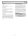
•
09727-008
•
•
The data is being analyzed in parallel with the gathering
of samples. The user should delay the analysis until the
samples are gathered.
Other programs are running on the PC.
The PC is too slow.
Start Sampling
This button allows the user to read samples from the AD7195.
Rev. 0 | Page 7 of 20
Figure 8. Error Message When Samples Are not Captured
UG-257
Evaluation Board User Guide
09727-009
ADC SETUP WINDOW
Figure 9. ADC Setup Window
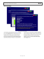
The ADC Setup window gives the user access to the AD7195
registers (see Figure 9). The user can write to the registers and
read from the registers. This window operates even when an
AD7195 evaluation board is not connected to the software. It
operates as an AD7195 configuration tool.
Buttons
ADC Reset
The ADC is reset to its default condition using this button.
ADC Read
Using this button allows the values of the registers on the
AD7195 to be read. The ADC Setup window displays the
hexadecimal values returned from the AD7195. Sections such
as Analog Inputs and Digital Filter are also updated to reflect
the AD7195 configuration.
Buffer drop-down menu. Finally, the Diagnostic drop-down
menu enables/disables the burnout currents.
Digital Filter
The output data rate, first filter notch, order of the sinc filter,
zero latency, and enabling/disabling the REJ60 bit are programmed
using the options within this section. The user can enter the
frequency of the first filter notch, and the software calculates
the value to be written to Bits FS[9:0] of the mode register.
Alternatively, the user can enter the FS[9:0] value in decimal,
and the software calculates the first filter notch. The user can
also select the sinc3/sinc4 filter and enable/disable zero latency.
The value to be written to the AD7195 is displayed in the
Registers HEX section.
Clock Configuration
The clock to be used by the AD7195 is selected in this section.
When an external master clock is selected, the clock frequency
must be entered in the MHz text box.
ADC Write
The information displayed in the Registers HEX section is
written to the AD7195.
Voltage Reference
Sections of the ADC Setup Window
Analog Inputs
Using the options within this section, the analog input channels
can be selected. Gain, polarity, chopping can also be selected.
The analog inputs can be buffered or unbuffered using the
The reference source and reference value are programmed in
this section. The user can enable/disable the reference detect
function and set the voltage of the reference.
When the reference setup is changed, the changes needed to
the Configuration Register are shown in the Registers HEX
section.
Rev. 0 | Page 8 of 20
Evaluation Board User Guide
UG-257
Excitation Mode
CONFIGURATION ASSIST TOOL
Use this drop-down menu to select ac excitation or dc
excitation.
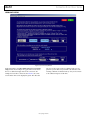
The AD7195 evaluation software can be used as a configuration
assist tool, even when an AD7195 evaluation board is not
connected. When the AD7195 evaluation board software is
open, click ADC Setup. The message in Figure 10 appears.
Click Ignore. The ADC Setup window opens. Use the ADC
Setup window to determine the values to be written to the
AD7195 on-chip registers for different configurations.
Bridge Power Down Switch
The low-side power switch is enabled or disabled using this
drop-down menu.
Mode of Operation
This drop-down menu allows the user to select different
modes of operation such as continuous conversion, single
cycle conversion and calibration.
Output Data Format
This drop-down menu allows the user to select the output
format of the data conversions and to enable the parity. When
several analog inputs are enabled, the Data + Status feature
should be enabled.
The Registers HEX section can be used. When the values in
this section are altered, the other sections of the ADC Setup
window are updated so that the user can easily see the impact
of the register changes. Alternatively, the user can modify the
other sections of the ADC Setup window and the Registers
HEX section is updated with the changes. Therefore, the user
can easily calculate the values to be written to the AD7195 for
different configurations.
This section displays the values to be written to the AD7195
registers. When features such as the analog input channel, gain,
and mode of operation are changed, the values in the Registers
HEX section are updated automatically. The user can write
directly to the Registers HEX section, altering the contents of
any register. The sections such as Analog Inputs and Digital
Filter are updated to reflect the changes in the Registers HEX
section.
Rev. 0 | Page 9 of 20
09727-010
Registers HEX
Figure 10. Configuration Tool
UG-257
Evaluation Board User Guide
09727-011
LOW NOISE QUICK TEST
Figure 11. Low Noise Quick Test
When Low Noise Quick Test is clicked in the main window,
the user can quickly and easily measure the rms noise of the
AD7195. The software configures the AD7195 to have a
gain of 128 and an output data rate of 4.7 Hz. In addition,
Channel AIN1-AIN2 is selected, and the reference voltage
is set to 5 V (the software assumes that the 5 V from the USB
is used as the reference to the AD7195). The software also
provides instructions on the link positions for the AD7195
evaluation board. When the instructions given on each window
are completed, click OK. The AD7195 gathers 100 samples,
displays the results in the waveform, and analyzes the data to
calculate the maximum conversion, minimum conversion, and
average conversion. The rms noise, peak-to-peak noise, and
resolution are also calculated.
Rev. 0 | Page 10 of 20
Evaluation Board User Guide
UG-257
09727-012
WEIGH SCALE DEMO
Figure 12. Weigh Scale Demo Window
A load cell can be connected directly to the AD7195 evaluation
board. When WeighScale Demo is clicked in the main window,
the user is guided through a series of windows that provide
information about connecting the load cell to the AD7195
evaluation board. The AD7195 is automatically configured to
have a gain of 128 and an output data rate of 10 Hz. In addition,
Channel AIN3-AIN4 and dc excitation re selected. When the
instructions given on each window are completed, click OK. The
AD7195 evaluation board gathers samples continuously and uses
batches of 20 samples to analyze the data. The software displays
the maximum voltage measured, the average voltage, the
minimum voltage, the rms noise, and the resolution. The
sample size used to process the data can be altered using the
Last # Samples text box.
Rev. 0 | Page 11 of 20
UG-257
Evaluation Board User Guide
09727-013
USER UNITS SETUP
Figure 13. User Units Setup Window
In the main window, click User Units Setup and the User Units
Setup window shown in Figure 13 appears. This window allows
the user to define the display units for the conversions. For
example, if a load cell is connected to the AD7195, the conversions from the ADC can be displayed in grams. The offset and
gain error of the system can also be calibrated. The user can
perform a system offset and system full-scale calibration. The
resulting coefficients are held in memory—they are not written
to the calibration registers of the ADC.
Rev. 0 | Page 12 of 20
Evaluation Board User Guide
UG-257
EVALUATION BOARD SCHEMATICS AND ARTWORK
09727-015
Figure 14. AD7195 Evaluation Board Schematic, Analog
Rev. 0 | Page 13 of 20
UG-257
Evaluation Board User Guide
09727-014
Figure 15. AD7195 Evaluation Board Schematic, Digital
Rev. 0 | Page 14 of 20
UG-257
09727-017
Evaluation Board User Guide
09727-016
Figure 16. AD7195 Evaluation Board Component Side View
Figure 17. AD7195 Evaluation Board Silkscreen
Rev. 0 | Page 15 of 20
Evaluation Board User Guide
09727-018
UG-257
Figure 18. AD7195 Evaluation Board Solder Side View
Rev. 0 | Page 16 of 20
Evaluation Board User Guide
UG-257
ORDERING INFORMATION
BILL OF MATERIALS
Table 2.
Qty.
1
1
1
1
1
1
1
1
4
5
1
1
4
1
9
2
4
17
3
6
4
1
3
9
5
10
1
16
2
1
5
1
1
2
1
1
1
1
1
1
2
2
Designator
U1
U2
U31
U32
U50
U51
U52
U53
LED1 to LED3, LED51
LED4 to LED8
XTAL1
XTAL51
D1
D31 to D34
Q51
C1 to C7, C15, C16
C52, C53
C8, C10, C11, C13
C19 to C24, C31 to C33,
C54 to C61
C9, C12, C14
C34 to C37, C50 to C51
C17, C18, C25, C30
L1
R1, R2, R5
R3 to R4, R8, R20 to R25
R6 to R7, R52 to R54
R9 to R15, R19, R50 to R51
R16
R17, R75 to R76
R18, R55 to R57, R62 to R73
R31, R32
R74
S1 to S5
B1
J1
J2, J3
J4
J5 to J9
J10
J31
J51
J52
Q1, Q4
Q2, Q7
Description
AD7195
ADR421 reference
5 V voltage regulator
3.3 V voltage regulator
10 kΩ, 64-step digipot
USB controller
64K I2C EEPROM
LCD connector
LED red, high intensity (>90 mcd), 0603
LED green, high intensity (>50 mcd), 0603
4.9152 MHz crystal
24 MHz crystal
Diode
Diode
N-MOSFET
Capacitor ceramic
12 pF ceramic capacitor
0.01 μF ceramic capacitor
0.1 μF ceramic capacitor
Manufacturer/Supplier
Analog Devices
Analog Devices
Analog Devices
Analog Devices
Analog Devices
Cypress Semiconductor
Microchip Technology, Inc.
FCI
Avago Technology
Avago Technology
Not inserted
AVX
ON Semiconductor
Philips
Infineon
Not inserted
Phycomp
Phycomp
Phycomp
Order No.
AD7195BCPZ
ADR421BRZ
ADP3303ARZ-5
ADP3303ARZ-3.3
AD5258BRMZ10
CY7C68013A-56LFXC
24LC64-I/SN
76341-308LF
HSMC-C191
HSME-C191
1 μF ceramic capacitor
4.7 μF ceramic capacitor
10 μF tantalum capacitor
Ferrite bead
0.0 Ω resistor
100 Ω resistor
1 kΩ resistor
10 kΩ resistor
1.5 Ω resistor
Resistor
100 Ω resistor
10 Ω resistor
47 Ω resistor
Switch
Clip for 9 V battery
2 × 4 way header
2 × 8 way header
1 × 8 way header
Connector, 50 Ω, straight, SMB
Screw terminal block
Connector, power jack, barrel, 2.1 mm, SMD
Connector, USB mini-B, SMD
Header
LCD module 2 × 16 char, 1 × 16-pin, top
LCD header
N-FET transistor
P-FET transistor
Phycomp
Phycomp
AVX
Tyco
Phycomp
Phycomp
Phycomp
Phycomp
Phycomp
Not inserted
Phycomp
Phycomp
Phycomp
Omron
Keystone
Tyco/Amp
Tyco/Amp
Phoenix Contact
Not inserted
Phoenix Contact
Lumberg
Molex
Not inserted
Everbouquet
Tyco
NPX
NPX
2238 246 13663
2255 206 13672
TAJA106M016R
BMB2A1000LN2
232270296001
232270461001
232270461002
232270461003
232270461508
Rev. 0 | Page 17 of 20
CX5032GB24000H0PESZZ
P6SMB6.8AT3G
BAT721C
BSS138N
2238 867 15129
2238 586 15636
2238 786 15649
232270461004
232270461009
232270464709
B3S-1000
593+594
1241050-4
1241050-8
1803332
1727010
1613_14
548190572
MC1602C-SYR
1-826629-6
BSH112
BSH201
UG-257
Evaluation Board User Guide
NOTES
Rev. 0 | Page 18 of 20
Evaluation Board User Guide
UG-257
NOTES
Rev. 0 | Page 19 of 20
UG-257
Evaluation Board User Guide
NOTES
ESD Caution
ESD (electrostatic discharge) sensitive device. Charged devices and circuit boards can discharge without detection. Although this product features patented or proprietary protection
circuitry, damage may occur on devices subjected to high energy ESD. Therefore, proper ESD precautions should be taken to avoid performance degradation or loss of functionality.
Legal Terms and Conditions
By using the evaluation board discussed herein (together with any tools, components documentation or support materials, the “Evaluation Board”), you are agreeing to be bound by the terms and conditions
set forth below (“Agreement”) unless you have purchased the Evaluation Board, in which case the Analog Devices Standard Terms and Conditions of Sale shall govern. Do not use the Evaluation Board until you
have read and agreed to the Agreement. Your use of the Evaluation Board shall signify your acceptance of the Agreement. This Agreement is made by and between you (“Customer”) and Analog Devices, Inc.
(“ADI”), with its principal place of business at One Technology Way, Norwood, MA 02062, USA. Subject to the terms and conditions of the Agreement, ADI hereby grants to Customer a free, limited, personal,
temporary, non-exclusive, non-sublicensable, non-transferable license to use the Evaluation Board FOR EVALUATION PURPOSES ONLY. Customer understands and agrees that the Evaluation Board is provided
for the sole and exclusive purpose referenced above, and agrees not to use the Evaluation Board for any other purpose. Furthermore, the license granted is expressly made subject to the following additional
limitations: Customer shall not (i) rent, lease, display, sell, transfer, assign, sublicense, or distribute the Evaluation Board; and (ii) permit any Third Party to access the Evaluation Board. As used herein, the term
“Third Party” includes any entity other than ADI, Customer, their employees, affiliates and in-house consultants. The Evaluation Board is NOT sold to Customer; all rights not expressly granted herein, including
ownership of the Evaluation Board, are reserved by ADI. CONFIDENTIALITY. This Agreement and the Evaluation Board shall all be considered the confidential and proprietary information of ADI. Customer may
not disclose or transfer any portion of the Evaluation Board to any other party for any reason. Upon discontinuation of use of the Evaluation Board or termination of this Agreement, Customer agrees to
promptly return the Evaluation Board to ADI. ADDITIONAL RESTRICTIONS. Customer may not disassemble, decompile or reverse engineer chips on the Evaluation Board. Customer shall inform ADI of any
occurred damages or any modifications or alterations it makes to the Evaluation Board, including but not limited to soldering or any other activity that affects the material content of the Evaluation Board.
Modifications to the Evaluation Board must comply with applicable law, including but not limited to the RoHS Directive. TERMINATION. ADI may terminate this Agreement at any time upon giving written notice
to Customer. Customer agrees to return to ADI the Evaluation Board at that time. LIMITATION OF LIABILITY. THE EVALUATION BOARD PROVIDED HEREUNDER IS PROVIDED “AS IS” AND ADI MAKES NO
WARRANTIES OR REPRESENTATIONS OF ANY KIND WITH RESPECT TO IT. ADI SPECIFICALLY DISCLAIMS ANY REPRESENTATIONS, ENDORSEMENTS, GUARANTEES, OR WARRANTIES, EXPRESS OR IMPLIED, RELATED
TO THE EVALUATION BOARD INCLUDING, BUT NOT LIMITED TO, THE IMPLIED WARRANTY OF MERCHANTABILITY, TITLE, FITNESS FOR A PARTICULAR PURPOSE OR NONINFRINGEMENT OF INTELLECTUAL
PROPERTY RIGHTS. IN NO EVENT WILL ADI AND ITS LICENSORS BE LIABLE FOR ANY INCIDENTAL, SPECIAL, INDIRECT, OR CONSEQUENTIAL DAMAGES RESULTING FROM CUSTOMER’S POSSESSION OR USE OF
THE EVALUATION BOARD, INCLUDING BUT NOT LIMITED TO LOST PROFITS, DELAY COSTS, LABOR COSTS OR LOSS OF GOODWILL. ADI’S TOTAL LIABILITY FROM ANY AND ALL CAUSES SHALL BE LIMITED TO THE
AMOUNT OF ONE HUNDRED US DOLLARS ($100.00). EXPORT. Customer agrees that it will not directly or indirectly export the Evaluation Board to another country, and that it will comply with all applicable
United States federal laws and regulations relating to exports. GOVERNING LAW. This Agreement shall be governed by and construed in accordance with the substantive laws of the Commonwealth of
Massachusetts (excluding conflict of law rules). Any legal action regarding this Agreement will be heard in the state or federal courts having jurisdiction in Suffolk County, Massachusetts, and Customer hereby
submits to the personal jurisdiction and venue of such courts. The United Nations Convention on Contracts for the International Sale of Goods shall not apply to this Agreement and is expressly disclaimed.
©2011 Analog Devices, Inc. All rights reserved. Trademarks and
registered trademarks are the property of their respective owners.
UG09727-0-5/11(0)
Rev. 0 | Page 20 of 20