1
KTQM87/mITX
KTD-N0886-A
The pulse of innovation
Error! Use the Home tab to apply Überschrift 1 to the text that you want to appear here.
Table of Contents
» Table of Contents «
1
Introduction ........................................................................................... 5
2
Installation Procedure .............................................................................. 6
2.1
Installing the Board ................................................................................................................ 6
2.2
Requirements IEC60950 ........................................................................................................... 7
3
System Specifications ............................................................................... 8
3.1
Component main data .............................................................................................................. 8
3.2
KTQM87 Block Diagram ........................................................................................................... 12
3.3
Processor Support Table .......................................................................................................... 13
3.4
System Memory support .......................................................................................................... 14
3.5
KTQM87 Graphics Subsystem .................................................................................................... 15
Intel® HD Graphics 4600 ........................................................................................................................... 15
Intel® HD Graphics 5200 ........................................................................................................................... 15
3-displays Configurations: ......................................................................................................................... 16
DP Adapters............................................................................................................................................. 16
3.6
Power Consumption................................................................................................................ 17
4
Connector Locations ............................................................................... 21
4.1
KTQM87/mITX - frontside ......................................................................................................... 21
4.2
KTQM87/mITX - backside ......................................................................................................... 22
5
Connector Definition .............................................................................. 23
6
IO-Area Connectors ................................................................................ 24
6.1
DP Connectors DP1, DP2, DP3 (J24, J22, J23) .............................................................................. 24
6.2
Ethernet Connectors ............................................................................................................... 25
6.3
USB Connectors (IO Area) ........................................................................................................ 26
USB Connector J35 (USB0, 1, 2 & 3) ............................................................................................................. 27
USB 10 & 11 (J9) ...................................................................................................................................... 28
USB 4&5 (J10) ......................................................................................................................................... 28
6.4
Audio Jack Connector Stack (J16) ............................................................................................. 29
7
Internal Connectors ................................................................................ 30
7.1
Power Connector (ATX+12V-24p) (J20) ....................................................................................... 30
7.2
Fan Connectors (J28 and J29) .................................................................................................. 31
7.3
PS/2 Keyboard and Mouse connector (KBDMSE) (J26).................................................................... 32
7.4
SATA (Serial ATA) Disk interface ................................................................................................ 33
7.5
USB Connectors (internal) ....................................................................................................... 34
7.6
Speaker connector (J34) ......................................................................................................... 34
7.7
SPDIF-Out (J33) .................................................................................................................... 34
7.8
Front Panel Connector (FRONTPNL) (J12) .................................................................................... 35
7.9
Serial COM1 – COM2 Ports (J19, J18) .......................................................................................... 36
7.10
LVDS Flat Panel Connector (J31) ............................................................................................... 37
KTQM87/mITX Users Guide
Error! Use the Home tab to apply Überschrift 1 to the text that you want to appear here.
Table of Contents
7.11
Feature Connector (J27).......................................................................................................... 38
7.12
“Load Default BIOS Settings” Jumper (J5) ................................................................................... 40
7.13
Always On jumper setting (J36) ................................................................................................ 41
7.14
SPI Connector (J32) ............................................................................................................... 42
7.15
ccTalk Connector (J25) ........................................................................................................... 43
7.16
LPC Connector (J30) ............................................................................................................... 43
8
Slot Connectors (PCIe, miniPCIe)............................................................... 44
8.1
PCIe Connectors .................................................................................................................... 44
PCI-Express x16 Connector (J8 PCIe x16) ...................................................................................................... 44
MiniPCIe with mSATA/USB2.0 & SIM-card support (J14) .................................................................................. 46
MiniPICe with mSATA & USB2.0 (J13) ........................................................................................................... 47
9
On-board -& mating connector types ......................................................... 48
10
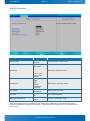
BIOS .................................................................................................... 49
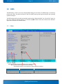
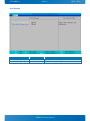
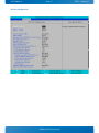
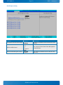
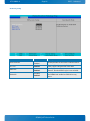
10.1
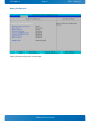
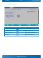
Main ................................................................................................................................... 49
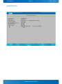
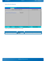
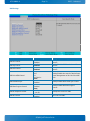
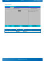
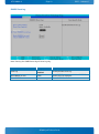
System Information .................................................................................................................................. 50
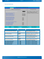
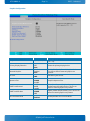
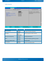
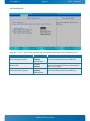
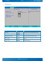
Boot Features .......................................................................................................................................... 51
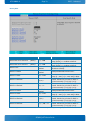
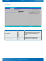
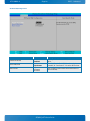
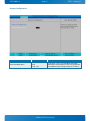
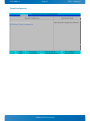
Network Stack .......................................................................................................................................... 53
Error Manager .......................................................................................................................................... 54
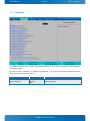
10.2
Advanced ............................................................................................................................. 55
Silicon Information ................................................................................................................................... 56
ACPI Configuration ................................................................................................................................... 57
Processor Configuration............................................................................................................................. 58
Peripheral Configuration ............................................................................................................................ 61
HDD Configuration .................................................................................................................................... 62
Memory Configuration ............................................................................................................................... 64
System Agent (SA) Configuration................................................................................................................. 71
South Bridge Configuration ........................................................................................................................ 78
Network Configuration .............................................................................................................................. 87
LAN Configuration .................................................................................................................................... 88
Hardware Health Configuration ................................................................................................................... 89
Kontron Configuration............................................................................................................................... 91
Display Configuration ................................................................................................................................ 92
SMBIOS Event Log .................................................................................................................................... 93
AMT Configuration .................................................................................................................................... 94
ME Configuration ...................................................................................................................................... 97
Thermal Configuration ............................................................................................................................... 98
ICC Configuration ................................................................................................................................... 101
Intel ® Rapid Start Technology ................................................................................................................. 102
10.3
Security ............................................................................................................................. 103
Secure Boot Configuration ....................................................................................................................... 104
TPM Configuration .................................................................................................................................. 105
10.4
Boot ................................................................................................................................. 106
10.5
Misc .................................................................................................................................. 107
10.6
Exit................................................................................................................................... 108
KTQM87/mITX Users Guide
KTD-N0886-A
Page 2
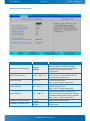
Document Details
Document Revision History
Revision
Date
By
Comment
A
12-1-2015
MLA
LVDS panel support description improved. Cooler PN corrected. Note -12V use.
Added PEG Bifurcation info. Added BIOS section. EXT_BAT max. 3.47 V. BIOS
section added. Added more DP adapter info.
0
6-11-2013
NRM/MLA
Preliminary version
Copyright Notice
Copyright 2013, KONTRON Technology A/S, ALL RIGHTS RESERVED.
No part of this document may be reproduced or transmitted in any form or by any means, electronically or
mechanically, for any purpose without the express written permission of KONTRON Technology A/S.
Trademark Acknowledgement
Brand and product names are trademarks or registered trademarks of their respective owners.
Disclaimer
KONTRON Technology A/S reserves the right to make changes without notice to any product, including
circuits and/or software described or contained in this manual in order to improve design and/or
performance.
Specifications listed in this manual are subject to change without notice. KONTRON Technology assumes no
responsibility or liability for the use of the described product(s), conveys no license or title under any
patent, copyright or mask work rights to these products and makes no representations or warranties that
these products are free from patent, copyright or mask work right infringement unless otherwise specified.
Applications that are described in this manual are for illustration purposes only. KONTRON Technology A/S
makes no representation or warranty that such application will be suitable for the specified use without
further testing or modification.
KTQM87/mITX Users Guide
KTD-N0886-A
Page 3
Document Details
Life Support Policy
KONTRON Technology’s PRODUCTS ARE NOT FOR USE AS CRITICAL COMPONENTS IN LIFE SUPPORT DEVICES OR
SYSTEMS WITHOUT EXPRESS WRITTEN APPROVAL OF THE GENERAL MANAGER OF KONTRON Technology A/S.
As used herein:
Life support devices or systems are devices or systems which (a) are intended for surgical implant into body
or (b) support or sustain life and whose failure to perform when properly used in accordance with
instructions for use provided in the labelling can be reasonably expected to result in significant injury to
the user.
A critical component is any component of a life support device or system whose failure to perform can be
reasonably expected to cause the failure of the life support device or system or to affect its safety or
effectiveness.
Warranty
KONTRON Technology warrants its products to be free from defects in material and workmanship during the
warranty period. If a product proves to be defective in material or workmanship during the warranty period
KONTRON Technology will, at its sole option, repair or replace the product with a similar product.
Replacement Product or parts may include remanufactured or refurbished parts or components.
The warranty does not cover:
1. Damage, deterioration or malfunction resulting from:
A. Accident, misuse, neglect, fire, water, lightning or other acts of nature, unauthorized
product modification or failure to follow instructions supplied with the product.
B. Repair or attempted repair by anyone not authorized by KONTRON Technology.
C. Causes external to the product, such as electric power fluctuations or failure.
D. Normal wear and tear.
E. Any other causes which does not relate to a product defect.
2. Removal, installation and set-up service charges.
Exclusion of damages:
KONTRON TECHNOLOGY LIABILITY IS LIMITED TO THE COST OF REPAIR OR REPLACEMENT OF THE PRODUCT.
KONTRON TECHNOLOGY SHALL NOT BE LIABLE FOR:
1. DAMAGE TO OTHER PROPERTY CAUSED BY ANY DEFECTS IN THE PRODUCT, DAMAGES BASED UPON
INCONVENIENCE, LOSS OF USE OF THE PRODUCT, LOSS OF TIME, LOSS OF PROFITS, LOSS OF
BUSINESS OPPORTUNITY, LOSS OF GOODWILL, INTERFERENCE WITH BUSINESS RELATIONSHIPS OR
OTHER COMMERCIAL LOSS, EVEN IF ADVISED OF THEIR POSSIBILITY OF SUCH DAMAGES.
2. ANY OTHER DAMAGES, WHETHER INCIDENTAL, CONSEQUENTIAL OR OTHERWISE.
3. ANY CLAIM AGAINST THE CUSTOMER BY ANY OTHER PARTY.
KTQM87/mITX Users Guide
KTD-N0886-A
Page 4
Document Details
KONTRON Technology Technical Support and Services
If you have questions about installing or using your KONTRON Technology Product, then please notice that
you will find many answers in this Users Guide. To obtain support please contact your local Distributor or
Field Application Engineer (FAE).
Before Contacting Support: Please be prepared to provide as much information as possible:
CPU Board
1. Type.
2. Part Number (find PN on label)
3. Serial Number if available (find SN on label)
Configuration
1. DRAM Type and Size.
2. BIOS Revision (find the version info in the BIOS Setup).
3. BIOS Settings different than Default Settings (refer to the BIOS Setup section).
System
1. O/S Make and Version.
2. Driver Version numbers (Graphics, Network, and Audio).
3. Attached Hardware: Harddisks, CD-Rom, LCD Panels etc.
If the Kontron Technology product seems to be defect and you want to return it for repair, please follow the
guide lines from the following page:
http://kontron.com/services/rma-information/kontron-technology-a-s/
KTQM87/mITX Users Guide
KTD-N0886-A
1
Page 5
Introduction
Introduction
This manual describes the KTQM87/mITX board made by KONTRON Technology A/S. This board will also be
denoted KTQM87 within this Users Guide.
The KTQM87 board is based on the QM87 chipset, support 4th generation Intel® Haswell i7 -, i5 -, i3 2Core
and 4Core mobile processors, and Celeron. See “Processor Support Table” for more specific details.
Use of this Users Guide implies a basic knowledge of PC-AT hard- and software. This manual is focused on
describing the KTQM87 board’s special features and is not intended to be a standard PC-AT textbook.
New users are recommended to study the short installation procedure stated in the following chapter
before switching-on the power.
All configuration and setup of the CPU board is either done automatically or manually by the user via the
BIOS setup menus. Only exception is the “Load Default BIOS Settings” Jumper.
Latest revision of this manual, datasheet, BIOS, drivers, BSP’s (Board Support Packages), Mechanical
drawings (2D and 3D) can be downloaded from here: http://www.kontron.com/products/boards-andmezzanines/embedded-motherboards/mini-itx-motherboards/ktqm87-mitx.html
KTQM87/mITX Users Guide
KTD-N0886-A
Page 6
2
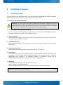
Installation Procedure
2.1
Installing the Board
Installation
To get the board running follow these steps. If the board shipped from KONTRON has already components
like RAM and CPU cooler mounted, then relevant steps below can be skipped.
1. Turn off the PSU (Power Supply Unit)
!
Warning: Turn off PSU (Power Supply Unit) completely (no mains power connected to the PSU) or
leave the Power Connectors unconnected while configuring the board. Otherwise components
(RAM, LAN cards etc.) might get damaged. Make sure only to use standard ATX PSU running the
board with non-compliant ATX PSU may damage the board within minutes.
2. Insert the DDR3 DIMM 240pin DIMM module(s)
Be careful to push it in the slot(s) before locking the tabs. For a list of approved DDR3 DIMMs contact your
Distributor or FAE. See also chapter “System Memory Support”.
3. Cooler Installation
Make sure the heat paste etc. on the cooler is intact and cover the full area of the CPU. Connect Cooler
Fan electrically to the FANCPU connector.
4. Connecting Interfaces
Insert all external cables for hard disk, keyboard etc. A monitor must be connected in order to change
BIOS settings.
5. Connect and turn on PSU
Connect PSU to the board by the ATX+12V-24p and the ATX+12V- 4p connectors.
6. Power Button
If the board does not start by itself when switching on the ATX PSU AC mains, then follow these
instructions to start the board. Install the Always On Jumper in the Always On position or toggle the
PWRBTN_IN# signal (available in the FRONTPNL connector), by momentary shorting pins 16
(PWRBTN_IN#) and pin 18 (GND). A “normally open” switch is recommended.
7. BIOS Setup
Enter the BIOS setup by pressing the <F2> key during boot up.
Enter “Exit Menu” and Load Setup Defaults.
Refer to the “BIOS Configuration / Setup“ section of this manual for details on BIOS setup.
Note: To clear all BIOS settings, including Password protection, activate “Load Default BIOS Settings”
Jumper for ⋲10 sec (without power connected).
KTQM87/mITX Users Guide
KTD-N0886-A
Page 7
Installation
8. Mounting the board in chassis
!
Warning: When mounting the board to chassis etc. please notice that the board contains
components on both sides of the PCB which can easily be damaged if board is handled without
reasonable care. A damaged component can result in malfunction or no function at all.
When fixing the Motherboard on a chassis it is recommended using screws with integrated washer and a
diameter of ⋲7mm. Do not use washers with teeth, as they can damage the PCB and cause short circuits.
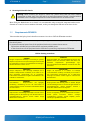
2.2
Requirements IEC60950
Take care when designing chassis interface connectors in order to fulfil the IEC60950 standard.
When an interface or connector has a VCC (or other power) pin which is directly connected to a power plane
like the VCC plane:
To protect the external power lines of the peripheral devices the customer has to ensure:
• Wires have suitable rating to withstand the maximum available power.
• That the enclosure of the peripheral device fulfils the fire protecting requirements of IEC60950.
Lithium battery precautions
CAUTION!
Danger of explosion if battery is incorrectly re- placed.
Replace only with same or equivalent type recommended
by manufacturer. Dispose of used batteries according to
the manufacturer’s instruc- tions.
VORSICHT!
Explosionsgefahr bei unsachgemäßem Austausch der
Batterie. Ersatz nur durch den selben oder einen vom
Hersteller
empfohlenen
gleichwertigen
Typ.
Entsorgung gebrauchter Batterien nach Anga- ben des
Herstellers.
ATTENTION!
Risque d'explosion avec l'échange inadéquat de la
batterie. Remplacement seulement par le même ou un
type équivalent recommandé par le producteur.
L'évacuation des batteries usagées conformément à des
indications du fabricant.
PRECAUCION!
Peligro de explosión si la batería se sustituye
incorrectamente. Sustituya solamente por el mismo o
tipo equivalente recomendado por el fabricante.
Disponga las baterías usadas según las instrucciones
del fabricante.
ADVARSEL!
Lithiumbatteri – Eksplosionsfare ved fejlagtig
håndtering. Udskiftning må kun ske med batteri af
samme fabrikat og type. Levér det brugte batteri tilbage
til leverandøren.
ADVARSEL!
Eksplosjonsfare ved feilaktig skifte av batteri. Benytt
samme batteritype eller en tilsvarende type anbefalt av
apparatfabrikanten. Brukte batterier kasseres i
henhold til fabrikantens instruksjoner.
VARNING!
Explosionsfara vid felaktigt batteribyte. Använd samma
batterityp eller en ekvivalent typ som rekommenderas av
apparattillverkaren. Kassera använt batteri enligt
fabrikantens instruktion.
VAROITUS!
Paristo voi räjähtää, jos se on virheellisesti asennettu.
Vaihda paristo ainoastaan lalteval- mistajan
suosittelemaan tyyppiln. Hävitä käytetty paristo
valmistajan ohjeiden mukaisesti.
KTQM87/mITX Users Guide
KTD-N0886-A
Page 8
3
System Specifications
3.1
Component main data
System Specification
The table below summarizes the features of the KTQM87/mITX embedded motherboard.
Form factor
KTQM87/mITX: miniITX (170.18 mm by 170.18 mm), Height approx. 39 mm (35.5 mm
from top of PCB board)
Processor
On board CPU variants Support 4rd Generation Intel® Core™ (Haswell Mobile) processors
BGA 1364 (max 47W TDP)
• Intel® Core™ i7
• Intel® Core™ i5
• Intel® Core™ i3
• Intel® Celeron
4x 5 GT/s point-to-point DMI interface to PCH and 2/3/4/6/8MB internal cache.
Memory
•
•
•
•
DDR3 DIMM 240pin socket (2 sockets)
Support single and dual ranks DDR3 1333/1600MT/s
(PC3-10600/PC3-12800)
Support system memory from 1x 1GB up to 2x 8GB.
Notes: Less than 4GB displayed in System Properties using 32bit OS
(Shared Video Memory/PCI resources is subtracted)
ECC supported
Chipset
Intel QM87 PCH (Platform Controller Hub)
• Intel ® VT-d (Virtualisation Technology for Directed I/O)
• Intel ® TXT (Trusted Execution Technology)
• Intel ® vPRO
• Intel ® AMT (Active Management Technology) version 9.0
• Intel ® A T (Anti-Theft Technology)
• Intel ® HD Audio Technology
• Intel ® RST (Rapid Storage Technology)
• Intel ® RRT (Rapid Recover Technology)
• SATA (Serial ATA) 6Gb/s and 3Gb/s.
• USB revision 2.0
• USB revision 3.0
• PCI Express revision 2.0
• ACPI 3.0b compliant
• Triple Display support (Triple Graphic Pipes)
• Blue-ray HD video playback
Security
•
Intel® Integrated TPM 1.2 support
Management
•
Intel® Active Management Technology (Intel® AMT) 9.0
KTQM87/mITX Users Guide
KTD-N0886-A
Page 9
System Specification
Audio
Audio, 7.1 Channel High Definition Audio Codec using the VIA VT1708S codec
• Line-in and Line-out
• Surround output: SIDE, LFE, CEN, BACK and FRONT
• Microphone: MIC1 and MIC2
• SPDIF-Out (electrical Interface only)
• On-board speaker (Electromagnetic Sound Generator like Hycom HY-05LF)
Video
Intel ® i3, i5 & i7 4rd Generation Mobile processors support Intel ® HD Graphics 4600.
3x digital display ports via the Intel® Haswell CPU:
• 3x DP (DisplayPorts), comply with DisplayPort 1.2 specification.
• HDMI panel support via DP to HDMI Adapter Converter.
• DVI panel support via DP to DVI Adapter Converter.
• VGA panel support via DP to VGA Adapter Converter.
• LVDS panel support up to 2 pixel/clock 24 bit colors (VESA and JEIDA)
• Triple independent pipes for Mirror or Triple independent display support
• Triple independent pipes for triple independent or cloned displays are supported
from OS. Any 3 displays via DP1, DP2, DP3 and LVDS can be used.
I/O Control
Via ITE IT8516E Embedded Controller via LPC Bus interface
Peripheral
interfaces
•
•
•
•
•
Four USB 3.0 / USB 2.0 on I/O area
Four USB 2.0 ports on internal pinrows
Two Serial ports (RS232) on internal pinrows
Four Serial ATA-600 (Two further SATA ports implements in mSATA connectors)
RAID 0/1/5/10 support
LAN Support
•
1x 10/100/1000Mbits/s LAN (ETHER1) using Intel® Clarksville WGI218LM Gigabit
PHY connected to QM87 supporting AMT 9.0
1x 10/100/1000Mbits/s LAN (ETHER2) using Intel® Pearsonville I211AT PCI Express
controller
PXE Netboot supported.
Wake On LAN (WOL) supported
•
•
•
Expansion
Capabilities
•
•
•
•
•
•
•
•
•
PCI-Express slots:
• Slot PCIex16 (Gen 2.0 & 3.0).
Support PEG Bifurcation 1x x16 (default) or 2x x8 or 1x x8 + 2x x4.
• 1x mPCIe/mSATA connector with USB 2.0 port
• 1x mPCIe/mSATA connector w.USB 2.0, support for 3G modem (SIM socket)
SMBus, compatible with ACCES BUS and I2C BUS, (via Feature connector)
SPI bus routed to SPI connector (BIOS Recovery module interface)
DDC/AUX Bus routed to DP connector (Auto detect to DDC when using passive DP to
HDMI or DVI adapters)
18 x GPIOs (General Purpose I/Os), (via Feature connector)
DAC, ADC, PWM and TIMER (Multiplexed), (via Feature connector)
WAKE UP / Interrupt Inputs (Multiplexed), (via Feature connector)
3 Wire Bus for GPIO Expansion (up to 152 GPIOs), (via Feature connector)
8 bit Timer output, (via Feature connector)
KTQM87/mITX Users Guide
KTD-N0886-A
Hardware
Monitor
Subsystem
Page 10
•
•
•
•
•
System Specification
Smart Fan control system, support Thermal® and Speed® cruise for two on-board
Fan connectors: CPU Fan (on-board) and System Fan (on-board)
Thermal inputs: CPU Die temperature (precision +/- 3ºC), System temperature
(precision +/- 3ºC)
Intrusion (Case Open) detect input, (via Feature connector)
Sleep S5# Indication, (via Feature connector)
System Powergood Signal, (via Feature connector)
Power
Supply Unit
ATX/BTX (w. ATX+12V) PSU, 24-pin and 4-pin
Battery
Exchangeable 3.0V Lithium battery for on-board Real Time Clock and CMOS RAM.
Manufacturer Panasonic / Part-number CR-2032L/BN, CR2032N/BN or CR-2032L/BE.
Approximate 6.2 years retention.
Current draw is less than 4.2µA when PSU is disconnected and 0 µA in S0 – S5.
CAUTION: Danger of explosion if the battery is incorrectly replaced. Replace only
with the same or equivalent type recommended by the manufacturer. Dispose of
used batteries according to the manufacturer’s instructions.
BIOS
Operating
Systems
Support
•
•
•
•
•
•
•
•
•
•
•
Kontron Technology / Phoenix BIOS (EFI core version)
Support for ACPI 3.0 ( Advanced Configuration and Power Interface), Plug & Play
• Suspend (S1 mode)
• Suspend To Ram (S3 mode)
• Suspend To Disk (S4 mode)
“Always On” BIOS power setting
RAID Support (RAID modes 0,1, 5 and 10)
Windows XP (32b*, limited support may apply)
Windows 7 (32b + 64b *)
Windows 8 (32b + 64b *)
Linux
VxWorks
WES7 (32b + 64b)
*= Out Of The Box installation test only.
KTQM87/mITX Users Guide
KTD-N0886-A
Environmental
Conditions
Page 11
System Specification
Operating:
0°C – 60°C operating temperature (forced cooling). It is the customer’s responsibility
to provide sufficient airflow around each of the components to keep them within
allowed temperature range.
10% - 90% relative humidity (non-condensing)
Storage:
-20°C – 70°C; lower limit of storage temperature is defined by specification restriction
of on-board CR2032 battery. Board with battery has been verified for storage
temperature down to -40°C by Kontron.
5% - 95% relative humidity (non-condensing)
Electro Static Discharge (ESD) / Radiated Emissions (EMI):
All Peripheral interfaces intended for connection to external equipment are ESD/ EMI
protected.
EN 61000-4-2:2000 ESD Immunity
EN55022:2006+A1:2007 class B Generic Emission Standard.
Electrical Fast Transients (EFT) (Burst):
EN 61000-4-4 Burst Immunity.
Safety:
IEC 60950-1: 2005, 2nd Edition
UL 60950-1
CSA C22.2 No. 60950-1
Product Category: Information Technology Equipment Including Electrical Business
Equipment. Product Category CCN: NWGQ2, NWGQ8. File number: E194252
Shock:
IAW IEC 60068-2-27, Test Ea, shock, 18 shocks 3 per axis, 6 directions.
Shock pulse 50g, 11ms halfsine.
Bump:
IAW IEC 60068-2-29, Test Eb, Bump, 3000 bumps, 500 per axis, 6 directions.
Half Sine Waveform Acceleration 2g; Pulse Duration 11ms.
Vibration:
IAW IEC 60068-2-64, Test Fh, Random Vibration. 90 min per axis, 3 axes, at 1.9 grms,
with PSD: 10-20 Hz: 0.05 g²/Hz and 20-500 Hz: -3dB/octave.
Theoretical MTBF:
219.028 / 161.225 hours @ 40ºC / 60ºC for the KTQM87/mITX
Restriction of Hazardous Substances (RoHS):
All boards in the KTQM87 family are RoHS compliant.
Capacitor utilization:
No Tantalum capacitors on board
Only Japanese brand Solid capacitors rated for 100 ºC used on board
KTQM87/mITX Users Guide
KTD-N0886-A
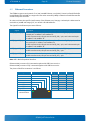
3.2
Page 12
System Specification
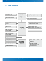
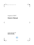
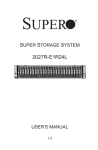
KTQM87 Block Diagram
3x DisplayPort 1.2
LVDS flat panel interface
Intel
Processor
HASWELL-mb
BGA
2x 240 pins DDR3 UDIMM 240-pin
Dual Channel (PC3 10600/12800)
Size 1GB – 16 GB
PCIe x16 (x16slot) Graphics
4x USB3.0/USB2.0
8x USB2.0
4x SATA (SATA3.0, RAID 0, 1, 5, 10)
(mSATA shared with mPCIe)
VIA Audio Codec
1x mPCIe/mSATA w. USB2.0
1x mPCIe/mSATA w. USB2.0 & SIM Card
LAN1 Intel Clarkville
10/100/1000Mb
PCH Lynx
Point-Mobile
SPI BIOS Flash
LAN2 Intel Pearsonville
10/100/1000Mb
TPM (Infineon)
Feature connector:
2x COM (RS232)
6-pin PS/2 Keyboard/Mouse
Embedded
Controller
ITE8516
SMBus/I2C
GPIO/DAC/ADC/PWM
GPIO expansion (up to 152)
Intruder detection
2x Fan (CPU/System)
KTQM87/mITX Users Guide
KTD-N0886-A
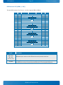
3.3
Page 13
System Specification
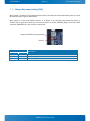
Processor Support Table
KTQM87 is designed to support the following BGA1364 Mobile processors:
4th generation Intel® Core™ i7 processor
4th generation Intel® Core™ i5 processor
4th generation Intel® Core™ i3 processor
4th generation Celeron
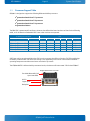
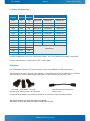
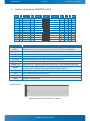
The BGA CPU is premounted from factory. Kontron has defined the board versions as listed in the following
table, so far all based on Embedded CPUs. Later other versions are expected.
KTQM87/mITX variants
CPU
Name
Sales PN
Speed
Turbo
Embed.
Cache
Sspec
TDG/Tj
KTQM87/mITX i7-4860EQ
KTQM87/mITX i7-4700EQ
KTQM87/mITX i5-4400E
KTQM87/mITX i3-4100E
KTQM87/mITX Cel-2000E
810554-4500
810550-4500
810551-4500
810552-4500
810553-4500
1.8GHz
2.4GHz
2.7GHz
1.6GHz
2.2GHz
3.2GHz
3.4 GHz
-
No
Yes
Yes
Yes
6MB
6MB
3MB
3MB
2MB
SR195
SR17L
SR17M
SR17N
47W/100ºC
47W/100ºC
37W/100ºC
37W/100ºC
37W/
Sufficient cooling must be applied to the CPU in order to remove the effect as listed as TDG (Thermal Design
Guideline) in above table. The sufficient cooling is also depending on the worst-case maximum ambient
operating temperature and the actual worst-case load of processor.
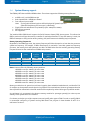
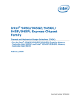
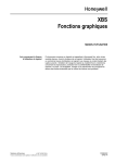
The KTQM87&mITX is delivered with premounted cooler, the Kontron PN 1056-2605 “CPU Cooler KTQM87”:
Height above PCB = 44.7mm
Fan Adda AD5012UB-C7B
Up to 7000 RPM
Alu fin
Cupper plate
Backplate
KTQM87/mITX Users Guide
KTD-N0886-A
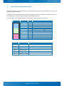
3.4
Page 14
System Specification
System Memory support
The KTQM87/mITX has two DDR3 UDIMM sockets. The sockets support the following memory features:
•
•
•
•
•
•
2x DDR3 1.5V/1.35V UDIMM 240-pin
Dual-channel with 1 UDIMM per channel
From 1GB and up to 2x 8GB.
Note: If using 32bit OS then less than 4GB in displayed in System Properties
(Shared Video Memory/PCI resources is subtracted)
Single/dual rank unbuffered 1333/1600MT/s (PC3-10600/PC3-12800)
SPD timings supported
ECC supported
The installed DDR3 DIMM should support the Serial Presence Detect (SPD) data structure. This allows the
BIOS to read and configure the memory controller for optimal performance. If non-SPD memory is used, the
BIOS will attempt to configure the memory settings, but performance and reliability may be impacted.
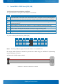
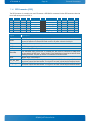
Memory Operating Frequencies
Regardless of the DIMM type used, the memory frequency will either be equal to or less than the processor
system bus frequency. For example, if DDR3 1600 memory is used with a 1333 MHz system bus frequency
processor, the memory clock will operate at 167 MHz. The table below lists the resulting operating memory
frequencies based on the combination of DIMMs and processor.
DIMM Type
DDR3 1066
DDR3 1333
DDR3 1600
DDR3 1600
Module
name
PC3-8500
PC3-10600
PC3-12800
PC3-12800
Memory Data
transfers
[MT/s]
1066
1333
1600
1600
Processor system
bus frequency
[MHz]
1066 / 1333
1333 / 1600
1333
1600
Resulting memory
clock frequency
[MHz]
133
167
167
200
Peak
transfer rate
[MB/s]
8533
10666
10666
12800
Notes: Kontron offers the following memory modules:
1GB DDR3 1333 PC3-10600, P/N: 1031-9872
2GB DDR3 1333 PC3-10600, P/N: 1054-3702
4GB DDR3 1333 PC3-10600, P/N: 1054-3703
8GB DDR3 1333 PC3-10600, P/N: 1054-3704
1GB DDR3 1600 PC3-12800, P/N: 1054-3706
2GB DDR3 1600 PC3-12800, P/N: 1054-3707
4GB DDR3 1600 PC3-12800, P/N: 1054-3708
8GB DDR3 1600 PC3-12800, P/N: 1052-5601
Memory modules have in general a much lower longevity than embedded motherboards, and therefor EOL
of modules can be expected several times during lifetime of the motherboard. Kontron guarantees that the
above P/N will be maintained so that EOL module will be replaced by other similar type of qualified module.
As a minimum it is recommend using Kontron memory modules for prototype system(s) in order to prove
stability of the system and as for reference.
For volume production you might request to test and qualify other types of RAM. In order to qualify RAM it
is recommend configuring 3 systems running RAM Stress Test program in heat chamber at 60⁰C for a
minimum of 24 hours.
KTQM87/mITX Users Guide
KTD-N0886-A
3.5
Page 15
System Specification
KTQM87 Graphics Subsystem
The KTQM87 equipped with Intel ® i3, i5 or i7 processor, supports Intel ® HD Graphics 4600, however the
i7-4860EQ supports Intel Iris™ Pro graphics 5200. All KTQM87 versions support three DisplayPort directly
from the processor. The DP interface supports the DisplayPort 1.2 specification. The PCH supports Highbandwidth Digital Content Protection for high definition content playback over digital interfaces. The PCH
also integrates audio codecs for audio support over DP interfaces.
Up to three displays (DP1, DP2, DP3 & LVDS) can be used simultaneously and be used to implement
independent or cloned display configuration. PCIe cards can be used to replace on-board graphics or in
combination with on-board graphics.
Intel® HD Graphics 4600
Features of the Intel HD Graphics 4600 build into the i3, i5 and i7 processors, includes:
•
High quality graphics engine supporting
o 3 Symmetric Pipe Support
o DirectX11.1 and OpenGL 4.x compliant and lower
o Open CL 1.2 and lower
o Core frequency of 350 - 1250 (Turbo) MHz
o Memory Bandwidth up to 25.6 GB/s
o Dynamic Video Memory Technology 5.0
o DP 1.2 MST (Multi-Stream Transport)
o PAVP
o HDCP
o Audio (Protected Content)
o Full AVC/VC1/MPEG2 HW Decode
o Full MVC HW Decode
•
DP1, DP2 & DP3
o 16/32bit colours in WQXGA 3840x2160 @ 60 Hz.
o Max HDMI resolution 4096x2304 @ 24 Hz
o DisplayPort standard 1.2
•
LVDS
o One or two pixels per clock, up to 1920x1200 24b bit colors.
o 12V for backlight, up to 2.5A
o 3.3V or 5V for panel power, up to 1.0A
o PWM Brightness/Dimming
o VESA and JEIDA color coding
Intel® HD Graphics 5200
The Intel Core i7-4860EQ support Intel Iris™ Pro graphics 5200 is almost the same as HD Graphics 4600, but
it has 40 execution units instead of 20 units and also embedded DRAM (L4 cache is added).
KTQM87/mITX Users Guide
KTD-N0886-A
Page 16
System Specification
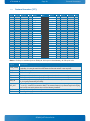
3-displays Configurations:
Display1
Display2 Display3
Max resolution @60 Hz
Display 1
Display2
Display3
LVDS
DP
DP
1920x1200
3840x2160
3840x2160
LVDS
HDMI
DP
1920x1200
2560x1600
3840x2160
LVDS
HDMI
HDMI
1920x1200
2560x1600
2560x1600
LVDS
HDMI
DVI
1920x1200
2560x1600
1920x1200
LVDS
DVI
DP
1920x1200
1920x1200
3840x2160
LVDS
DVI
DP
1920x1200
1920x1200
3840x2160
HDMI
HDMI
DP
2560x1600
2560x1600
3840x2160
HDMI
DVI
DP
2560x1600
1920x1200
3840x2160
DVI
DVI
DP
1920x1200
1920x1200
3840x2160
DP
DP
DP
3840x2160
3840x2160
3840x2160
HDMI
HDMI
HDMI
HDMI
HDMI
DVI
HDMI
DVI
DVI
DVI
DVI
DVI
Not allowed
By DVI and HDMI means using “DP to DVI passive adapter” and “DP to HDMI passive adapter” respectively.
If using “Active adapter” it will be same as “DP” in above table.
DP Adapters
Use of DP Adapter Converters (3rd party accessories) can provide HDMI, DVI or VGA panel support.
The Kontron DP to VGA is the only active Adapter, so that both Kontron DP to HDMI and DP to DMI are
passive adapters. The DP to HDMI supports the HDMI 1.4a specification including audio codec.
DP to VGA DP to HDMI DP to DVI
PN 1045-5779 PN 1045-5781 PN 1045-5780
Cable DP Extender cable 200mm
PN1051-7619
For alle the above adapter’s the maximum resolution is: 1920x1200. Extension cable available:
Alternative adapters with integrated cable are available:
KAB-ADAPT-DP-VGA, KAB-ADAPT-DP-HDMI and KAB-ADAPT-DP-DVI.
KTQM87/mITX Users Guide
KTD-N0886-A
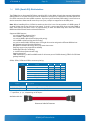
3.6
Page 17
System Specification
Power Consumption
In order to ensure safe operation of the board, the ATX+12V power supply must monitor the supply voltage
and shut down if the supplies are out of range – refer to the actual power supply specification. Please note,
In order to keep the power consumption to a minimal level, boards do not implement a guaranteed
minimum load. In some cases, this can lead to compatibility problems with ATX power supplies, which
require a minimum load to stay in regulation. The KTQM87 board must be powered through the ATX+12V-4p
(4-pole) and the ATX+12V-24p (24-pole) connectors using standard ATX power supply.
ATX12V supply: Both ATX+12V-4p connector and ATX+12V-24p connector must be used in according to the
ATX12V PSU standard.
Warning: Hot Plugging power supply is not supported. Hot plugging might damage the board.
The requirements to the supply voltages are as follows:
Supply
Min
Max
Note
VCC3.3
3.135V
3.465V
Should be ±5% for compliance with the ATX specification
Vcc
4.75V
5.25V
Should be ±5% for compliance with the ATX specification.
Should be +5/ -0% to meet the USB standard.
+12V
11.4V
12.6V
Should be ±5% for compliance with the ATX specification
–12V
–13.2V
–10.8V
Should be ±10% for compliance with the ATX specification
-5V
-5,50V
-4.5V
Not required for the KTQM87 boards
5VSB
4.75V
5.25V
Should be ±5% for compliance with the ATX specification
Note: -12V is only used for COM ports (COM1 and COM2).
KTQM87/mITX Users Guide
KTD-N0886-A
Page 18
System Specification
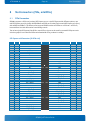
Total System power example
More detailed Static Power Consumption
On the following pages the power consumption of different boards in different configurations are listed.
For each configuration the power consumptions result are listed in 5 tables:
1. Windows 7 Idle
2. Windows 7 3Dmark 2006
3. Windows 7 Intel TAT, 100% on all CPU cores and GFX
4. Windows 7 S3 (Sleep)
5. Windows 7 S5 (Shutdown)
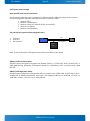
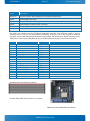
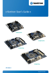
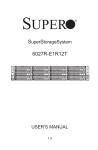
The principal test system and test equipment used
1.
2.
3.
Fluke 289
Fluke 179
ATX rail switch
Gnd
KTQM87
PSU
ATX supplies
Current
Probe
Note: Power consumption of PSU (power loss), Monitor and HDD are not included.
KTQM87/mITX Low Power Setup:
Standard system configuration equipped with Internal graphics, 1x SATA disks, Intel i7-4700EQ CPU, 1x
DIMM (4GB Module), DP Monitor, PS2 Keyboard & Mouse,1x 16GB USB 3.0 Stick, 12V active cooler, 400W
ATX PSU.
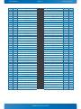
KTQM87/mITX High Power Setup:
Standard system configuration equipped with PCIe x16 graphics card, mSATA 32GB, 4x SATA disks, Intel i74700EQ CPU, 2x DIMM (4GB Modules), DP Monitor, PS2 Keyboard & Mouse, 2x 16GB USB 3.0 Sticks, 2x
16GB USB 2.0 Sticks, 12V active cooler, 400W ATX PSU.
KTQM87/mITX Users Guide
KTD-N0886-A
Page 19
System Specification
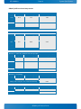
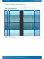
KTQM87/mITX Low Power Setup results:
Windows 7 – Idle
Supply Voltage / [V]
+12V
12.3
Current draw/ [mA]
147
Power consumption/ [W]
1.81
+12V_P4
12.3
305
3.75
+5V
+3V3
5VSB
Total
5.21
3.39
5.07
450
249
0
2.34
0.84
0.00
8.75
Windows 7 – 3DMark2006
Supply
Voltage / [V]
Current draw/ [mA]
Power consumption/ [W]
+12V
12.23
320
3.91
+12V_P4
12.14
1658
20.13
+5V
5.2
850
4.42
+3V3
3.38
248
0.84
5VSB
5.07
0
0.00
Total
29.30
Windows 7 – Intel TAT 100% all CPU cores and GFX
Supply
Voltage / [V]
Current draw/ [mA]
Power consumption/ [W]
+12V
12.19
319
3.89
+12V_P4
11.85
4039
47.86
+5V
5.2
1024
5.32
+3V3
3.36
247
0.83
5VSB
5.05
0
0.00
Total
57.91
Windows 7 – S3 (Sleep)
Supply
Voltage / [V]
Current draw/ [mA]
Power consumption/ [W]
5VSB
5.07
184
0.93
Total (+12V, +12V_P4, +5V, +3V3 are all 0 mA)
Windows 7 – S5 (Shutdown)
Supply Voltage / [V]
Current draw/ [mA]
5VSB
5.06
127
Total (+12V, +12V_P4, +5V, +3V3 are all 0 mA)
0.93
Power consumption/ [W]
0.64
0.64
KTQM87/mITX Users Guide
KTD-N0886-A
Page 20
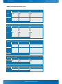
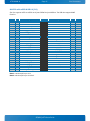
KTQM87/mITX High Power Setup results:
Windows 7 – Idle
Supply Voltage / [V]
+12V
12.25
Current draw/ [mA]
730
Power consumption/ [W]
8.94
+12V_P4 12.26
332
4.07
+5V
+3V3
5VSB
Total
778
2728
0
4.02
9.14
0.00
26.17
5.17
3.35
5.06
Windows 7 – 3DMark2006
Supply
Voltage / [V]
Current draw/ [mA]
Power consumption/ [W]
+12V
12.2
1236
15.08
+12V_P4 12.21
1166
14.24
+5V
5.17
828
4.28
+3V3
3.34
3478
11.62
5VSB
5.05
0
0.00
Total
45.21
Windows 7 – Intel TAT 100% all CPU cores and GFX
Supply
Voltage / [V]
Current draw/ [mA]
Power consumption/ [W]
+12V
12.1
1492
18.05
+12V_P4 11.97
3630
43.45
+5V
5.17
823
4.25
+3V3
3.32
3735
12.40
5VSB
5.05
0
0.00
Total
78.16
Windows 7 – S3 (Sleep)
Supply
Voltage / [V]
Current draw/ [mA]
Power consumption/ [W]
5VSB
5.06
568
2.87
Total (+12V, +12V_P4, +5V, +3V3 are all 0 mA)
2.87
Windows 7 – S5 (Shutdown)
Supply Voltage / [V] Current draw/ [mA]
5VSB
5.06
663
Total (+12V, +12V_P4, +5V, +3V3 are all 0 mA)
Power consumption/ [W]
3.35
3.35
KTQM87/mITX Users Guide
System Specification
KTD-N0886-A
Page 21
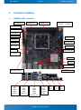
4
Connector Locations
4.1
KTQM87/mITX - frontside
J36 Always On
J6 DDR3 Slot 1
Connector Location
J1 SATA2
J4 SATA3
J7 DDR3 Slot 0
J2 SATA1
J3 SATA0
J12 FRONTPNL
J21 ATX+12V-4p
J29 FANCPU
J28 FANSYS
J8 PCIe x16
J18 COM2
J15 SIM CARD
J19 COM1
J25 ccTALK
J34 Speaker
J30 LPC
J33 SPDIF OUT
J27 FEATURE
J31 LVDS
J32 SPI
J5 load default
J20 ATX+12V-24p
J9
LAN1
USB10
USB11
(USB2.0)
J10
LAN2
USB4
USB5
(USB2.0)
J26 PS2 KBD/MSE
J35
USB3
USB2
USB1
USB0
(USB 3.0/2.0)
J16
Audio
Line1
Speaker
Mic1
KTQM87/mITX Users Guide
J22
DP2
J23
DP3
J24
DP1
KTD-N0886-A
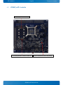
4.2
Page 22
Connector Location
KTQM87/mITX - backside
J13 mPCIe/mSATA4 w. USB13
J14 mPCIe/mSATA5 w. USB12 & SIM Card
System Temperature Sensor U79 (LM75)
KTQM87/mITX Users Guide
KTD-N0886-A
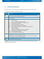
5
Page 23
Connector Definition
Connector Definition
The following sections provide pin definitions and detailed description of all on-board connectors.
The connector definitions follow the following notation:
Column
name
Pin
Description
Signal
The mnemonic name of the signal at the current pin. The notation “XX#” states that the signal
“XX” is active low.
Type
AI:
AO:
I:
IO:
IOT:
IS:
IOC:
IOD:
NC:
O:
OC:
OT:
LVDS:
PWR:
Shows the pin-numbers in the connector. The graphical layout of the connector definition
tables is made similar to the physical connectors.
Analogue Input.
Analogue Output.
Input, TTL compatible if nothing else stated.
Input / Output. TTL compatible if nothing else stated.
Bi-directional tristate IO pin.
Schmitt-trigger input, TTL compatible.
Input / open-collector Output, TTL compatible.
Input / Output, CMOS level Schmitt-triggered. (Open drain output)
Pin not connected.
Output, TTL compatible.
Output, open-collector or open-drain, TTL compatible.
Output with tri-state capability, TTL compatible.
Low Voltage Differential Signal.
Power supply or ground reference pins.
Ioh: Typical current in mA flowing out of an output pin through a grounded load, while the
output voltage is > 2.4 V DC (if nothing else stated).
Iol: Typical current in mA flowing into an output pin from a VCC connected load, while the
output voltage is < 0.4 V DC (if nothing else stated).
Pull U/D
On-board pull-up or pull-down resistors on input pins or open-collector output pins.
Note
Special remarks concerning the signal.
The abbreviation TBD is used for specifications which are not available yet or which are not sufficiently
specified by the component vendors.
KTQM87/mITX Users Guide
KTD-N0886-A
Page 24
IO-Area Connectors
6
IO-Area Connectors
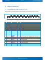
6.1
DP Connectors DP1, DP2, DP3 (J24, J22, J23)
The DP (DisplayPort) connectors are based on standard DP type Foxconn 3VD51203-H7JJ-7H or similar.
19
20
Pin
1
2
3
4
5
6
7
8
9
10
11
12
Config1
14
Config2
16
17
18
19
20
18
15
16
Signal
Description
Lane 0 (p)
GND
Lane 0 (n)
Lane 1 (p)
GND
Lane 1 (n)
Lane 2 (p)
GND
Lane 2 (n)
Lane 3 (p)
GND
Lane 3 (n)
13
15
17
Aux or DDC
selection
(Not used)
Aux Channel (+)
Aux Ch (p)
or DDC Clk
GND
Aux Channel (-)
Aux Ch (n)
or DDC Data
Hot Plug
Return
3.3V
13
14
11
12
9
10
7
8
5
6
3
4
1
2
Type Note
LVDS
PWR
LVDS
LVDS
PWR
LVDS
LVDS
PWR
LVDS
LVDS
PWR
LVDS
Internally pull down (1Mohm).
I
Aux channel on pin 15/17 selected as default (when NC)
DDC channel on pin 15/17, If HDMI adapter used (3.3V)
O
Internally connected to GND
AUX (+) channel used by DP
DDC Clk used by HDMI
PWR
AUX (-) channel used by DP
DDC Data used by HDMI
I
Internally pull down (100Kohm).
PWR Same as GND
PWR Fused by 1.5A resetable PTC fuse.
KTQM87/mITX Users Guide
KTD-N0886-A
6.2
Page 25
IO-Area Connectors
Ethernet Connectors
The KTQM87 supports two channels of 10/100/1000Mb Ethernet, one (LAN1) is based on Intel® Clarkville
i218LM Gigabit PHY with AMT 9.0 support and one other controller (LAN2) are based on Intel® Pearsonville
i218AT PCI Express controller.
In order to achieve the specified performance of the Ethernet port, Category 5 twisted pair cables must be
used with 10/100MB and Category 5E, 6 or 6E with 1Gb LAN networks.
The signals for the Ethernet ports are as follows:
Signal
Description
MDI[0]+ / MDI[0]-
In MDI mode, this is the first pair in 1000Base-T, i.e. the BI_DA+/- pair, and is the
transmit pair in 10Base-T and 100Base-TX.
In MDI crossover mode, this pair acts as the BI_DB+/- pair, and is the receive pair
in 10Base-T and 100Base-TX.
MDI[1]+ / MDI[1]-
In MDI mode, this is the second pair in 1000Base-T, i.e. the BI_DB+/- pair, and is
the receive pair in 10Base-T and 100Base-TX.
In MDI crossover mode, this pair acts as the BI_DA+/- pair, and is the transmit pair
in 10Base-T and 100Base-TX.
MDI[2]+ / MDI[2]-
In MDI mode, this is the third pair in 1000Base-T, i.e. the BI_DC+/- pair.
In MDI crossover mode, this pair acts as the BI_DD+/- pair.
MDI[3]+ / MDI[3]-
In MDI mode, this is the fourth pair in 1000Base-T, i.e. the BI_DD+/- pair.
In MDI crossover mode, this pair acts as the BI_DC+/- pair.
Note: MDI = Media Dependent Interface.
Ethernet LAN1 (connector J9) is mounted together with USB Ports 10 and 11.
Ethernet LAN2 (connector J10) is mounted together with USB Ports 4 and 5.
The pinout of the RJ45 connectors is as follows:
Signal
MDI0+
MDI0MDI1+
MDI2+
MDI2MDI1MDI3+
MDI3Flashing =>
communication
PIN
Type
Ioh/Iol
On => 1GB link
8
7
6
5
4
3
2
1
KTQM87/mITX Users Guide
Note
KTD-N0886-A
6.3
Page 26
IO-Area Connectors
USB Connectors (IO Area)
The KTQM87 board contains a EHCI (Enhanced Host Controller Interface) and a XHCI (Extensible Host
Controller Interface). The EHCI controller supports eight USB 2.0 ports allowing data transfers up to
480Mb/s. The XHCI controller supports up to six USB 3.0 ports allowing data transfers up to 5Gb/s. Four of
the USB 3.0 ports are shared with four of the USB 2.0 ports (USB0 – USB3).
Note: Not all USB 2.0 and USB 3.0 ports are physically connected to the board.
Legacy Keyboard/Mouse and wakeup from sleep states are supported. Over-current detection on all USB
ports is supported. The following USB connectors are available in the IO Area.
USB 2.0/3.0 Port 0, 1, 2 & 3 are supplied on the combined quad USB connector (J35).
USB 2.0 Port 4, 5 are supplied on the combined 2xUSB and LAN connector (J10).
USB 2.0 Port 10, 11 are supplied on the combined 2xUSB and LAN connector (J9).
For USB2.0 cabling it is required to use only HiSpeed USB cable, specified in USB2.0 standard:
For USB3.0 cabling it is required to use only HiSpeed USB cable, specified in USB3.0 standard:
KTQM87/mITX Users Guide
KTD-N0886-A
Page 27
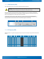
IO-Area Connectors
USB Connector J35 (USB0, 1, 2 & 3)
The quad USB connector J35, Ports 0, 1, 2 and 3 supports USB3.0/USB2.0.
Note Type
1
1
1
1
Signal
USBn+ USBnRXn+ RXnTXn+ TXn(n= 0,1,2,3)
5V/SB5V
Signal
PIN
Signal
Type
IO
PWR
IO
IO
PWR
USB3- USB3+
5V/SB5V
1 2 3 4 GND
RX2- 5 6 7 8 9 TX2+
RX1+
TX1GND
IO
PWR
IO
IO
IO
PWR
IO
IO
PWR
USB2- USB2+
5V/SB5V
1 2 3 4 GND
RX2- 5 6 7 8 9 TX2+
RX2+
TX2GND
IO
PWR
IO
IO
IO
PWR
IO
IO
PWR
USB1- USB1+
5V/SB5V
1 2 3 4 GND
RX1- 5 6 7 8 9 TX1+
RX1+
TX1GND
IO
PWR
IO
IO
IO
PWR
IO
IO
PWR
USB0- USB0+
5V/SB5V
1 2 3 4 GND
RX0- 5 6 7 8 9 TX0+
RX0+
TX0GND
IO
PWR
IO
IO
Note
Description
Differential pair works as serial differential receive/transmit data lines.
5V supply for external devices. SB5V is supplied during power-down to allow wakeup
on USB device activity. Protected by resettable 2A fuse covering both USB ports.
KTQM87/mITX Users Guide
KTD-N0886-A
Page 28
IO-Area Connectors
USB 10 & 11 (J9)
The USB ports 10 and 11 supports USB2.0, are located in the stacked rear IO connectors J9 with LAN1.
Note Type
1
IO
PWR
PWR
1
IO
PWR
PWR
Signal
Signal
PIN
Signal
Type
5V/SB5V
USB10- USB10+
1 2 3 4 GND
GND
IO
PWR
5V/SB5V
USB11- USB11+
1 2 3 4 GND
GND
IO
PWR
Note
Description
USB10+ USB10USB11+ USB11-
Differential pair works as serial differential receive/transmit data lines.
5V supply for external devices. SB5V is supplied during power-down to allow wakeup
on USB device activity. Protected by resettable 2A fuse covering both USB ports.
5V/SB5V
USB 4&5 (J10)
The USB ports 4 and 5 supports USB2.0, are located in the stacked rear IO connectors J10 with LAN2.
Note Type
Signal
USB4+ USB4USB5+ USB55V/SB5V
1
IO
PWR
PWR
1
IO
PWR
PWR
Signal
PIN
Signal
Type
5V/SB5V
USB4- USB4+
1 2 3 4 GND
GND
IO
PWR
5V/SB5V
USB5- USB5+
1 2 3 4 GND
GND
IO
PWR
Note
Description
Differential pair works as serial differential receive/transmit data lines.
5V supply for external devices. SB5V is supplied during power-down to allow wakeup
on USB device activity. Protected by resettable 2A fuse covering both USB ports.
KTQM87/mITX Users Guide
KTD-N0886-A
6.4
Page 29
IO-Area Connectors
Audio Jack Connector Stack (J16)
The on-board Audio circuit implements up to 8 Channel High Definition Audio via SPDIF-Out connector, see
SPDIF-Out (J33) description.
Interface is based on UAA (Universal Audio Architecture), featuring five 24-bit stereo DACs and three 20bit stereo ADCs. The Following Audio connector is available in IO Area.
Audio Speakers, Line-in and Microphone are available in a stacked audiojack connector:
Signal
Type
TIP
RING
SLEEVE
LINE1-IN-L
LINE1-IN-R
GND
IA
IA
PWR
1.0VRMS, 30kΩ
1.0VRMS, 30kΩ
TIP
RING
SLEEVE
OUT-L
OUT-R
GND
OA
OA
PWR
For headphone, max 1.6VRMS
For headphone, max 1.6VRMS
TIP
RING
SLEEVE
MIC1-L
MIC1-R
GND
IA
IA
PWR
1.0VRMS, 30kΩ
1.0VRMS, 30kΩ
Signal
Description
Note
Note
LINE1-IN-L Line In signal Left
LINE1-IN-R Line In signal Right
OUT-L
Speaker Out Left
Shared with J34 pin header connector
OUT-R
Speaker Out Right
Shared with J34 pin header connector
MIC1-L
Microphone In Left
MIC1-R
Microphone In Right
KTQM87/mITX Users Guide
KTD-N0886-A
Page 30
7
Internal Connectors
7.1
Power Connector (ATX+12V-24p) (J20)
Internal Connectors
The KTQM87 boards are designed to be supplied from a standard ATX (or BTX) power supply. Use of BTX
supply is not required for operation, but may be required to drive high-power PCIe cards.
ATX+12V-24p Power Connector:
Note
Type
PWR
PWR
PWR
PWR
I
PWR
PWR
PWR
PWR
PWR
PWR
PWR
Signal
3V3
+12V
+12V
SB5V
P_OK
GND
5V
GND
5V
GND
3V3
3V3
PIN
12 24
11 23
10 22
9 21
8 20
7 19
6 18
5 17
4 16
3 15
2 14
1 13
Signal
GND
5V
5V
5V
-5V
GND
GND
GND
PSON#
GND
-12V
3V3
Type
PWR
PWR
PWR
PWR
PWR
PWR
PWR
PWR
OC
PWR
PWR
PWR
Note
1
See chapter “Power Consumption” regarding input tolerances on 3.3V, 5V, SB5V, +12 and -12V (also refer
to ATX specification version 2.2).
ATX+12V-4p Power Connector (J21):
Note
Type
PWR
PWR
Signal
GND
GND
2
1
PIN
4
3
Signal
+12V
+12V
Type
PWR
PWR
Note
1
1
Note 1: Use of the ATX+12V-4p in Power Connector is required for operation of KTQM87.
Signal
P_OK
PS_ON#
Description
P_OK is power good signal driven by the ATX Power Supply and indicating that the +5VDC and
+3.3VDC outputs are above the undervoltage thresholds.
The recommended electrical and timing characteristics of the P_OK (PWR_OK) signal are
provided in the ATX12V Power SupplyDesign Guide.
It is strongly recommended to use an ATX or BTX supply, in order to provide supervision of the 5V
and 3V3 supplies. These supplies are not supervised on-board.
Active low open drain signal from the board to the power supply to turn on the power supply
outputs. Signal must be pulled high by the power supply.
Warning: Hot plugging any of the two power connectors (J20 and J21) is not allowed. Hot plugging might
damage the board. In other words, turn off main supply etc. to makesure all the power lines (+12V, 5V,
SB5V, 3.3V, -5V, -12V) are turned off when connecting to the motherboard.
KTQM87/mITX Users Guide
KTD-N0886-A
7.2
Page 31
Internal Connectors
Fan Connectors (J28 and J29)
The FAN1SYS (J28) can be used to power, control and monitor a fan for chassis ventilation etc.
The FANCPU (J29) is used for the connection of the FAN for the CPU.
The 4pin header is recommended to be used for driving 4-wire type Fan in order to implement FAN speed
control. 3-wire Fan support is also possible, but no fan speed control is integrated.
4-pin Mode:
3-pin Mode:
Signal
PWM
TACHO
Header
Pin
1
2
3
4
Signal
PWM
TACHO
12V
GND
Description
PWM output
Tacho signal
Power +12V
Ground
Type
O-3.3
I
PWR
PWR
Header
Pin
1
2
3
4
Signal
Description
Not used
Tacho signal
Power +12V
Ground
Type
TACHO
12V
GND
I
PWR
PWR
Description
PWM output signal for FAN speed control.
Tacho input signal from the fan, for rotation speed supervision RPM (Rotation Per Minute). The
signal shall be generated by an open collector transistor or similar. Onboard is a pull-up
resistor 4K7 to +12V. The signal has to be pulsed and onboard circuit is prepared for two pulses
per rotation.
12V
+12V supply for fan. A maximum of 2000mA can be supplied from this pin.
GND
Power Supply GND signal
KTQM87/mITX Users Guide
KTD-N0886-A
7.3
Page 32
Internal Connectors
PS/2 Keyboard and Mouse connector (KBDMSE) (J26)
Attachment of a PS/2 keyboard/mouse can be done through the pinrow connector KBDMSE (J26).
Both interfaces utilize open-drain signalling with on-board pull-up.
The PS/2 mouse and keyboard is supplied from SB5V when in standby mode in order to enable keyboard or
mouse activity to bring the system out from power saving states. The supply is provided through a 1.1A
resettable fuse.
PIN
1
2
3
4
5
6
Signal
KBDCLK
KBDDAT
MSCLK
MSDAT
5V/SB5V
GND
Type
IOD
IOD
IOD
IOD
PWR
PWR
Ioh/Iol
/14mA
/14mA
/14mA
/14mA
-
Pull U/D
2K7
2K7
2K7
2K7
-
Note
Signal Description – Keyboard & and mouse Connector (KBDMSE).
Signal
Description
MSCLK
Bi-directional clock signal used to strobe data/commands from/to the PS/2 mouse.
MSDAT
Bi-directional serial data line used to transfer data from or commands to the PS/2 mouse.
KDBCLK
Bi-directional clock signal used to strobe data/commands from/to the PC-AT keyboard.
KBDDAT
Bi-directional serial data line used to transfer data from or commands to the PC-AT keyboard.
Available cable kit:
PN 1053-2384 Bracket Cable 6-Pin to PS2-Kbd-Mse
KTQM87/mITX Users Guide
KTD-N0886-A
7.4
Page 33
Internal Connectors
SATA (Serial ATA) Disk interface
The KTQM87 has an integrated SATA Host controller (PCH in the QM87 chipset) that supports independent
DMA operation on six ports. One device can be installed on each port for a maximum of six SATA devices via
four SATA connectors and two mSATA connector. A point-to-point interface (SATA cable) is used for host to
device connections. Data transfer rates of up to 6.0/3.0/1.5Gb/s are supported on all SATA ports.
Note: Before installing OS on a SATA drive make sure the drive is not a former member of a RAID system. If
so some hidden data on the disk has to be erased. To do this, connect two SATA drives and select RAID in
BIOS. Save settings and select <Ctrl> <I> while booting to enter the RAID setup menu. Now the hidden
RAID data will be erased from the selected SATA drive.
Supported SATA features:
2 to 4-drive RAID 0 (data striping)
2-drive RAID 1 (data mirroring)
3 to 4-drive RAID 5 (block-level striping with parity).
4-drive RAID 10 (data striping and mirroring)
2 to 4-drive matrix RAID, different parts of a single drive can be assigned to different RAID devices.
AHCI (Advanced Host Controller Interface)
NCQ (Native Command Queuing). NCQ is for faster data access.
Swap bay support (not supported on mSATA)
Intel® Rapid Recover Technology
2 – 256TB volume (Data volumes only)
Capacity expansion
TRIM in Windows 7 (in AHCI and RAID mode for drives not part of a RAID volume). (TRIM is for SSD data
garbage handling).
SATA0, SATA1, SATA2 and SATA3 connector pinning:
PIN
Signal
Type
1
2
3
4
5
6
7
GND
SATA* TX+
SATA* TXGND
SATA* RXSATA* RX+
GND
PWR
-
PWR
-
PWR
-
Signal
SATA* RX+ / RXSATA* TX+ / TX-
Ioh/Iol Note
Description
Host transmitter differential signal pair
Host receiver differential signal pair
“*” specifies 0, 2, 3, 4, 5 depending on SATA port.
Available cable kit:
PN 821035 Cable SATA 500mm
KTQM87/mITX Users Guide
KTD-N0886-A
7.5
Page 34
Internal Connectors
USB Connectors (internal)
The following USB2.0 ports are available on Internal Pinrows:
USB2.0 Port 8 and 9 are supplied on the internal FRONTPNL connector (J12).
See “Front Panel Header” description.
USB2.0 Port 12 and 13 are supplied on the internal mPCIe connectors (J14 and J13) witch have included
mSATA and USB connections. See “PCIe Connectors” description.
7.6
Speaker connector (J34)
The headphone interface is available through the connector J34 (4 pins). These outputs are shared with
the Speaker Audio Jack connector (green).
Up to 100 dB Signal-to-Noise Ratio (SNR).
Header
7.7
Pin
4
3
2
1
Signal
HPOUT-R
GND
HPOUT-L
GND
Type
AO
PWR
AO
PWR
SPDIF-Out (J33)
The digital audio interface (electrical SPDIF-Out) is available through the 2 pin connector J33 and can be
used to implement 8 (7.1) Channel High Definition Audio.
Circuit is based on high fidelity 8-channel HD audio codec which is compatible with Intel HD Audio
specification and supports stereo 24-bit resolution and up to 192 kHz sample rate for DACs/ADCs.
Up to 90 dB Signal-to-Noise Ratio (SNR).
16/20/24-bit S/PDIF TX Outputs supporting 48K/96K/44.1K/88.2 KHz sample rate
Header
1
Pin
Signal
Type
2
GND
PWR
1
SPDIF_OUT
O-3.3
KTQM87/mITX Users Guide
KTD-N0886-A
7.8
Page 35
Internal Connectors
Front Panel Connector (FRONTPNL) (J12)
Note
Pull
Ioh/
Type
Signal
U/D
Iol
PWR USB8_5V
USB8USB8+
PWR
GND
NC
NC
PWR
+5V
- 25/25mA O SATA_LED#
PWR
GND
4K7
I
RSTIN#
PWR
SB3V3
PWR
AGND
AI
MIC2-L
PIN
1
3
5
7
9
11
13
15
17
19
21
23
2
4
6
8
10
12
14
16
18
20
22
24
Ioh/ Pull
Note
Iol U/D
USB9_5V PWR USB9USB9+
GND
PWR LINE2-L
+5V
PWR SUS_LED
O 7mA PWRBTN_IN# I
1K1
GND
PWR LINE2-R
AGND
PWR MIC2-R
AI
Signal
Type
Signal
USB8_5V &
USB9_5V
USB8+/USB8-
Description
5V supply for external devices. SB5V is supplied during powerdown to allow wakeup on
USB device activity. Protected by active power switch 1A fuse for each USB ports.
Universal Serial Bus Port 8 Differentials: Bus Data/Address/Command Bus.
USB9+/USB9-
Universal Serial Bus Port 11 Differentials: Bus Data/Address/Command Bus.
+5V
Maximum load per pin is 1A (using IDC connector) or 2A (using crimp terminals).
SATA_LED#
SATA Activity LED (active low signal). 3V3 output when passive.
SUS_LED
Suspend Mode LED (active high signal). Output 3.3V via 470Ω.
PWRBTN_IN#
Power Button In. Toggle this signal low to start the ATX / BTX PSU and boot the board.
RSTIN#
Reset Input. When pulled low for a minimum 16ms, the reset process will be initiated.
The reset process continues even though the Reset Input is kept low.
LINE2
Line2 is second stereo Line signals
MIC2
MIC2 is second stereo microphone input.
SB3V3
Standby 3.3V voltage
AGND
Analogue Ground for Audio
Available cable kit:
PN 821042 Cable Front Panel Open-End, 300 mm
KTQM87/mITX Users Guide
KTD-N0886-A
7.9
Page 36
Internal Connectors
Serial COM1 – COM2 Ports (J19, J18)
Two RS232 serial ports are available on the KTQM87.
The typical definition of the signals in the COM ports is as follows:
Signal
Description
TxD
Transmitted Data, sends data to the communications link. The signal is set to the marking state (12V) on hardware reset when the transmitter is empty or when loop mode operation is initiated.
RxD
Received Data, receives data from the communications link.
DTR
Data Terminal Ready, indicates to the modem etc. that the on-board UART is ready to establish a
communication link.
DSR
Data Set Ready, indicates that the modem etc. is ready to establish a communications link.
RTS
Request To Send, indicates to the modem etc. that the on-board UART is ready to exchange data.
CTS
Clear To Send, indicates that the modem or data set is ready to exchange data.
DCD
Data Carrier Detect, indicates that the modem or data set has detected the data carrier.
RI
Ring Indicator, indicates that the modem has received a ringing signal from the telephone line.
The pinout of Serial ports COM1 (J19), COM2 (J18)
Note Ioh/Iol Type Signal PIN
I
DCD
1 2
I
RxD
3 4
O
TxD
5 6
O
DTR
7 8
PWR GND
9 10
Signal
DSR
RTS
CTS
RI
5V
Type
I
O
I
I
PWR
Ioh/Iol Note
-
1
Note 1: The COM1, COM2 5V supply is fused with common 1.5A resettable fuse.
DB9 adapter cables (PN 821016 200mm long and 821017 100mm long) are available for implementing
standard COM ports on chassis.
Available cable kit (DB9 adapter cables):
PN 821017 - 100 mm or PN 821016 - 200 mm
KTQM87/mITX Users Guide
KTD-N0886-A
Page 37
Internal Connectors
7.10 LVDS Flat Panel Connector (J31)
The LVDS connector is based on 40 pole connector type Don Connex C44-40BSB1-G.
Note
Max. 0.5A
Max. 0.5A
Max. 0.5A
Max. 0.5A
Max. 0.5A
2K2Ω, 3.3V
3.3V level
3.3V level
Max. 0.5A
Max. 0.5A
Type
Signal
PWR
+12V
PWR
+12V
PWR
+12V
PWR
+5V
PWR
LCDVCC
OT
DDC CLK
OT
BKLTCTL
OT
BKLTEN#
LVDS LVDS A0LVDS LVDS A1LVDS LVDS A2LVDS LVDS ACLKLVDS LVDS A3PWR
GND
LVDS LVDS B0LVDS LVDS B1LVDS LVDS B2LVDS LVDS BCLKLVDS LVDS B3PWR
GND
PIN
1 2
3 4
5 6
7 8
9 10
11 12
13 14
15 16
17 18
19 20
21 22
23 24
25 26
27 28
29 30
31 32
33 34
35 36
37 38
39 40
Signal
+12V
+12V
GND
GND
LCDVCC
DDC DATA
VDD ENABLE
GND
LVDS A0+
LVDS A1+
LVDS A2+
LVDS ACLK+
LVDS A3+
GND
LVDS B0+
LVDS B1+
LVDS B2+
LVDS BCLK+
LVDS B3+
GND
Type
PWR
PWR
PWR
PWR
PWR
OT
OT
PWR
LVDS
LVDS
LVDS
LVDS
LVDS
PWR
LVDS
LVDS
LVDS
LVDS
LVDS
PWR
Note
Max. 0.5A
Max. 0.5A
Max. 0.5A
Max. 0.5A
Max. 0.5A
2K2Ω, 3.3V
3.3V level
Max. 0.5A
Max. 0.5A
Max. 0.5A
Note: The KTQM87 on-board LVDS connector supports single and dual channel, 18/24bit SPWG panels up
to a resolution of 1600x1200 or 1920x1080 and with limited frame rate up to 1920x1200.
Signal Description – LVDS Flat Panel Connector:
Signal
LVDS A0..A3
LVDS ACLK
LVDS B0..B3
LVDS BCLK
BKLTCTL
BKLTEN#
VDD ENABLE
LCDVCC
DDC CLK
Description
LVDS A Channel data
LVDS A Channel clock
LVDS B Channel data
LVDS B Channel clock
Backlight control (1), PWM signal to implement voltage in the range 0-3.3V
Backlight Enable signal (active low) (2)
Output Display Enable.
VCC supply to the display. 5V or 3.3V (1A Max.) selected in BIOS setup menu. Power
sequencing depends on LVDS panel selection. (Shared with eDP connector)
DDC Channel Clock
Notes: Windows API will be available to operate the BKLTCTL signal. Some Inverters have a limited voltage
range 0- 2.5V for this signal: If voltage is > 2.5V the Inverter might latch up. Some Inverters
generates noise on the BKLTCTL signal, causing the LVDS transmission to fail (corrupted picture on
the display). By adding a 1Kohm resistor in series with this signal, mounted at the Inverter end of
the cable kit, the noise is limited and the picture is stable.
If the Backlight Enable is required to be active high then, check the following BIOS Chipset setting:
Backlight Signal Inversion = Enabled.
KTQM87/mITX Users Guide
KTD-N0886-A
7.11
Page 38
Internal Connectors
Feature Connector (J27)
Note Pull U/D
2
2M/
-
Ioh/Iol
25/25mA
25/25mA
-
-
8/8mA
8/8mA
-
Type
I
O
O
NC
PWR
IOT
IOT
IOT
IOT
PWR
I
I
I
IOT
IOT
PWR
O
Signal
PIN
CASE_OPEN# 1 2
S5#
3 4
PWR_OK
5 6
7 8
SB3V3
9 10
GPIO0
11 12
GPIO2
13 14
GPIO4
15 16
GPIO6
17 18
GND
19 20
GPIO8
21 22
GPIO10
23 24
GPIO12
25 26
GPIO14
27 28
GPIO16
29 30
GND
31 32
EGCLK
33 34
EGAD
35 36
PWR +12V
37 38
NC 39 40
PWR GND
41 42
PWR GND
43 44
Signal
SMBC
SMBD
EXT_BAT
SB5V
GPIO1
GPIO3
GPIO5
GPIO7
GND
GPIO9
GPIO11
GPIO13
GPIO15
GPIO17
GND
EGCS#
TMA0
GND
GND
S3#
Type Ioh/Iol
/4mA
/4mA
PWR NC PWR IOT
IOT
IOT
IOT
PWR I
I
IOT
IOT
IOT
PWR O
8/8mA
O
PWR NC PWR O
25/25mA
Pull U/D Note
10K/
1
10K/
1
-
Notes: 1. Pull-up to +3V3Dual (+3V3 or SB3V3). 2. Pull-up to on-board Battery. 3. Pull-up to +3V3.
Signal
SMBC
Description
CASE OPEN, used to detect if the system case has been opened. This signal’s status is
readable, so it may be used like a GPI when the Intruder switch is not required.
SMBus Clock signal
SMBD
SMBus Data signal
S3#
S3 sleep mode, active low output, optionally used to deactivate external system.
S5#
SB3V3
S5 sleep mode, active low output, optionally used to deactivate external system.
PoWeR OK, signal is high if no power failures are detected. (This is not the same as the
P_OK signal generated by ATX PSU).
(EXTernal BATtery) option for connecting + terminal of an external primary cell battery (2.5
- 3.47 V) (– terminal connected to GND). The external battery is protected against charging
and can be used with/without the on-board battery installed.
Max. load is 0.75A (1.5A < 1 sec.)
SB5V
StandBy +5V supply.
CASE_OPEN#
PWR_OK
EXT_BAT
KTQM87/mITX Users Guide
KTD-N0886-A
Signal
Page 39
Internal Connectors
EGCLK
Description
General Purpose Inputs / Output. These Signals may be controlled or monitored through
the use of the KT-API-V2 (Application Programming Interface).
Extend GPIO Clock signal
EGAD
Extend GPIO Address Data signal
EGCS#
Extend GPIO Chip Select signal, active low
TMA0
Timer Output
+12V
Max. load is 0.75A (1.5A < 1 sec.)
GPIO0..17
The GPIO’s are controlled via the ITE IT8516F Embedded Controller. Each GPIO has 100pF to ground,
clamping Diode to 3V3 and has multiplexed functionality. Some pins can be DAC (Digital to Analogue
Converter output), PWM (Pulse Width Modulated signal output), ADC (Analogue to Digital Converter input),
TMRI (Timer Counter Input), WUI (Wake Up Input), RI (Ring Indicator Input) or some special function.
Signal
GPIO0
GPIO1
GPIO2
GPIO3
GPIO4
GPIO5
GPIO6
GPIO7
GPIO8
GPIO9
GPIO10
GPIO11
GPIO12
GPIO13
GPIO14
GPIO15
GPIO16
GPIO17
IT8516F pin name
DAC0/GPJ0
DAC1/GPJ1
DAC2/GPJ2
DAC3/GPJ3
PWM2/GPA2
PWM3/GPA3
PWM4/GPA4
PWM5/GPA5
ADC0/GPI0
ADC1/GPI1
ADC2/GPI2
ADC3/GPI3
ADC4/WUI28/GPI4
RI1#/WUI0/GPD0
RI2#/WUI1/GPD1
TMRI0/WUI2/GPC4
TMRI1/WUI3/GPC6
L80HLAT/BAO/WUI24/GPE0
Type
AO/IOS
AO/IOS
AO/IOS
AO/IOS
O8/IOS
O8/IOS
O8/IOS
O8/IOS
AI/IS
AI/IS
AI/IS
AI/IS
AI/IS/IS
IS/IS/IOS
IS/IS/IOS
IS/IS/IOS
IS/IS/IOS
O4/O4/IS/IOS
Description
Available cable kit and Break-Out-Board:
PN 1052-5885 Cable, Feature 44pol 1 to1, 300mm
PN 820978 Feature BOB (Break-Out-Board)
KTQM87/mITX Users Guide
KTD-N0886-A
Page 40
Internal Connectors
7.12 “Load Default BIOS Settings” Jumper (J5)
The “Load Default BIOS Settings” Jumper (J5) can be used to recover from incorrect BIOS settings. As an
example, an incorrect BIOS setting which causes the attached display not to turn on can be erased by this
Jumper.
The Jumper has 3 positions: Pin 1-2, Pin2-3 (default position) and not mounted.
!
Jumper (in default position)
Warning
Don’t leave the jumper in
position 1-2, otherwise if power
is disconnected, the battery will
fully deplete within a few weeks.
J5
pin1-2
X
-
pin2-3
X
-
J5 pin1
Description
Don’t use. (Board do not boot with jumper in this position)
Default position
Load Default BIOS Settings and erase Password
To Load Default BIOS Settings and erase password:
1.
2.
3.
4.
5.
6.
7.
Turn off power completely (no SB5V).
Remove the Jumper completely from J5.
Turn on power.
Motherboard beeps fast 20 times and turns off.
Turn off power.
Move the Jumper back to position 2-3 (default position).
Turn on power, use the Power On Button (PWRBTN_IN#) if required to boot.
Motherboard might automatically reboot a few times. Wait until booting is completed.
KTQM87/mITX Users Guide
KTD-N0886-A
Page 41
Internal Connectors
7.13 Always On jumper setting (J36)
When jumper is installed in the (J36) Always On position, then the Board will automatically power up, when
the external power supply is switched ON.
When jumper is in the (J36) Default position, or if jumper is not mounted, then Always On feature is
disabled and it might be necessary to activate the power on buttom (PWRBTN_IN#) at the Front Panel
connector (FRONTPNL) in order to switch on the board.
Jumper in Default position (pin 2&3)
J36 pin1
J36
pin1-2
X
-
pin2-3
X
-
Description
Always On: Will make Auto power On when power in switched ON.
Default: Always On feature is disabled.
Same as Default.
KTQM87/mITX Users Guide
KTD-N0886-A
Page 42
Internal Connectors
7.14 SPI Connector (J32)
The SPI Connector is normally not used. If however a SPI BIOS is connected via the SPI Connector then the
board will attempt to boot from it.
Note Pull U/D Ioh/Iol Type
Signal
1
CLK
I
CS0#
10K/
NC
10K/
IO
MOSI
IO
MISO
1K
IO SPI_IO2_#WP
Signal
CLK
SB3V3
PIN
Signal
Type Ioh/Iol Pull U/D Note
1 2
SB3V3
PWR
3 4
ADDIN
IO
/10K
5 6
NC
7 8
ISOLATE#
IO
100K
9 10
GND
PWR
11 12 SPI_IO3_#HOLD IO
1K
Description
Serial Clock
3.3V Standby Voltage power line. Normally output power, but when Motherboard is
turned off then the on-board SPI Flash can be 3.3V power sourced via this pin.
CS0#
CS0# Chip Select 0, active low.
ADDIN
ADDIN input signal must be NC.
MOSI
Master Output, Slave Input.
ISOLATE#
The ISOLATE# input, active low, is normally NC, but must be connected to GND when
programming the SPI flash. Power Supply to the Motherboard must be turned off when
loading SPI flash. The pull up resistor is connected via diode to 5VSB.
MISO
Master Input, Slave Output
SPI Data I/O: A bidirectional signal used to support Dual IO Fast Read, Quad IO Fast Read
SPI_IO2_#WP
and Quad Output Fast Read modes. The signal is not used in Dual Output Fast Read mode.
SPI Data I/O: A bidirectional signal used to support Dual IO Fast Read, Quad IO Fast Read
SPI_IO3_#HOLD
and Quad Output Fast Read modes. The signal is not used in Dual Output Fast Read mode.
KTQM87/mITX Users Guide
KTD-N0886-A
Page 43
Internal Connectors
7.15 ccTalk Connector (J25)
The ccTalk interface uses a 4-pin connector identical to the Fan connectors.
!
Warning: Caution must be exercised to avoid inserting a CcTalk header into a FAN connector
as this might result in damage to the CcTalk device, motherboard or both!
Serial protocol used in money transaction industry. Peripherals such as coin acceptors, bill validators,
automatic payment equipment such as transportation, ticketing, payphones, amusement machines and
retail cash management use ccTalk to talk to the host controller.
ccTalk transfer asynchronously at 4800 -9600 baud, character frames via single wire bidirectional
communication at TTL level. It has ‘multi-drop’ support for devices all having unique addresses. It can
easily expandable command interface and has some DES encryption. No licensing.
Header
Pin
1
2
3
4
Signal
VCC5
N.C.
GND
DATA
Description
Power +5V
Not connected
Ground
Serial data line (RXD/TXD)
Type
PWR
NC
PWR
IO
7.16 LPC Connector (J30)
The LPC connector is in general unsupported. Only under special circumstances may the LPC interface be of
interest.
Note
Pull
Ioh/Iol Type
Signal
U/D
PWR
LPC CLK
PWR LPC FRAME#
LPC RST#
LPC AD3
+3V3
LPC AD0
SMB_CLK
SB3V3
GND
SUS_STAT#
PIN
1
3
5
7
9
11
13
15
17
19
2
6
8
10
12
14
16
18
20
Signal
GND
KEY
+5V
LPC AD2
LPC AD1
GND
SMB_DATA
LPC SERIRQ
CLKRUN#
TPM_DRQ#0
KTQM87/mITX Users Guide
Type Ioh/Iol
Pull
Note
U/D
KTD-N0886-A
Page 44
8
Slot Connectors (PCIe, miniPCIe)
8.1
PCIe Connectors
Slot Connectors
KTQM87 supports 1 xPCIe x16 (16-lane) PCI Express port, 2 x miniPCI Express with different options, one
miniPCI Express ports (J14) with mSATA,USB2.0 and SIM-card Socket (J15) one miniPCI Express port (J13)
with mSATA and USB2.0. The PCIex16 slot supports PEG Bifurcation 2x PCIex8 or 1x PCIe x8 + 2x PCIe x4,
but need Riser Card with bifurcation functionality to work.
The 16-lane (x16) PCI Express (J8) (PCIe 2.0 and PCIe 3.0) port can be used for external PCI Express cards
inclusive graphics card. Maximum theoretical bandwidth using 16 lanes is 16 GB/s.
PCI-Express x16 Connector (J8 PCIe x16)
Note
Type
Signal
+12V
+12V
+12V
GND
SMB_CLK
SMB_DATA
GND
+3V3
NC
SB3V3
WAKE#
PIN
B1 A1
B2 A2
B3 A3
B4 A4
B5 A5
B6 A6
B7 A7
B8 A8
B9 A9
B10 A10
B11 A11
NC
GND
PEG_TXP[0]
PEG_TXN[0]
GND
CLKREQ
GND
PEG_TXP[1]
PEG_TXN[1]
GND
GND
PEG_TXP[2]
PEG_TXN[2]
GND
GND
PEG_TXP[3]
PEG_TXN[3]
GND
NC
CLKREQ
GND
PEG_TXP[4]
PEG_TXN[4]
B12
B13
B14
B15
B16
B17
B18
B19
B20
B21
B22
B23
B24
B25
B26
B27
B28
B29
B30
B31
B32
B33
B34
A12
A13
A14
A15
A16
A17
A18
A19
A20
A21
A22
A23
A24
A25
A26
A27
A28
A29
A30
A31
A32
A33
A34
KTQM87/mITX Users Guide
Signal
NC
+12V
+12V
GND
NC
NC
NC
NC
+3V3
+3V3
RST#
GND
PCIE_x16 CLK
PCIE_x16 CLK#
GND
PEG_RXP[0]
PEG_RXN[0]
GND
NC
GND
PEG_RXP[1]
PEG_RXN[1]
GND
GND
PEG_RXP[2]
PEG_RXN[2]
GND
GND
PEG_RXP[3]
PEG_RXN[3]
GND
NC
NC
GND
Type
Note
KTD-N0886-A
Page 45
GND
GND
PEG_TXP[5]
PEG_TXN[5]
GND
GND
PEG_TXP[6]
PEG_TXN[6]
GND
GND
PEG_TXP[7]
PEG_TXN[7]
GND
CLKREQ
GND
PEG_TXP[8]
PEG_TXN[8]
GND
GND
PEG_TXP[9]
PEG_TXN[9]
GND
GND
PEG_TXP[10]
PEG_TXN[10]
GND
GND
PEG_TXP[11]
PEG_TXN[11]
GND
GND
PEG_TXP[12]
PEG_TXN[12]
GND
GND
PEG_TXP[13]
PEG_TXN[13]
GND
GND
PEG_TXP[14]
PEG_TXN[14]
GND
GND
PEG_TXP[15]
PEG_TXN[15]
GND
CLKREQ
NC
B35
B36
B37
B38
B39
B40
B41
B42
B43
B44
B45
B46
B47
B48
B49
B50
B51
B52
B53
B54
B55
B56
B57
B58
B59
B60
B61
B62
B63
B64
B65
B66
B67
B68
B69
B70
B71
B72
B73
B74
B75
B76
B77
B78
B79
B80
B81
B82
A35
A36
A37
A38
A39
A40
A41
A42
A43
A44
A45
A46
A47
A48
A49
A50
A51
A52
A53
A54
A55
A56
A57
A58
A59
A60
A61
A62
A63
A64
A65
A66
A67
A68
A69
A70
A71
A72
A73
A74
A75
A76
A77
A78
A79
A80
A81
A82
KTQM87/mITX Users Guide
Slot Connectors
PEG_RXP[4]
PEG_RXN[4]
GND
GND
PEG_RXP[5]
PEG_RXN[5]
GND
GND
PEG_RXP[6]
PEG_RXN[6]
GND
GND
PEG_RXP[7]
PEG_RXN[7]
GND
NC
GND
PEG_RXP[8]
PEG_RXN[8]
GND
GND
PEG_RXP[9]
PEG_RXN[9]
GND
GND
PEG_RXP[10]
PEG_RXN[10]
GND
GND
PEG_RXP[11]
PEG_RXN[11]
GND
GND
PEG_RXP[12]
PEG_RXN[12]
GND
GND
PEG_RXP[13]
PEG_RXN[13]
GND
GND
PEG_RXP[14]
PEG_RXN[14]
GND
GND
PEG_RXP[15]
PEG_RXN[15]
GND
KTD-N0886-A
Page 46
Slot Connectors
MiniPCIe with mSATA/USB2.0 & SIM-card support (J14)
Slot J14 supports mPCIe or mSATA cards (uses SATA5 Port), USB2.0 and SIM-card socket (J15).
The SIM-card socket makes it possible to use a 2G/3G-wireless modem in this mPCIe slot.
The USB does support WAKE function.
Note
Type
NC
NC
1
PWR
PWR
NC
NC
PWR
PWR
PWR
PWR
PWR
PWR
PWR
NC
NC
NC
NC
Signal
WAKE#
NC
NC
CLKREQ#
GND
PCIE_mini CLK#
PCIE_mini CLK
GND
1
3
5
7
9
11
13
15
PIN
2
4
6
8
10
12
14
16
Signal
+3V3
GND
+1.5V
UIM_PWR
UIM_DATA
UIM_CLK
UIM_RESET
UIM_VPP
Type
PWR
PWR
PWR
PWR
NC
NC
NC
NC
UIM_IC_DM
UIM_IC_DP
GND
SATA5_RXP
SATA5_RXN
GND
GND
SATA5_TXN
SATA5_TXP
GND
GND
+3V3
+3V3
SATA_DET5#
NC
NC
NC
NC
17
19
21
23
25
27
29
31
33
35
37
39
41
43
45
47
49
51
18
20
22
24
26
28
30
32
34
36
38
40
42
44
46
48
50
52
GND
W_Disable#
RST#
+3V3
GND
+1.5V
SMB_CLK
SMB_DATA
GND
USB12N
USB12P
GND
NC
NC
NC
+1.5V
GND
+3V3
PWR
Note 1: 10K ohm pull-up to 3V3.
Note 2: 2K2 ohm pull-up to 3V3 Dual.
KTQM87/mITX Users Guide
Note
2
PWR
PWR
PWR
PWR
IO
IO
PWR
NC
NC
NC
PWR
PWR
PWR
KTD-N0886-A
Page 47
Slot Connectors
MiniPICe with mSATA & USB2.0 (J13)
Slot J13 supports mPCIe or mSATA cards (uses SATA5 Port) and USB2.0. The USB does support WAKE
function.
Note
Type
NC
NC
1
PWR
PWR
NC
PWR
PWR
PWR
PWR
PWR
PWR
PWR
Signal
WAKE#
NC
NC
CLKREQ#
GND
PCIE_mini CLK#
PCIE_mini CLK
GND
1
3
5
7
9
11
13
15
PIN
2
4
6
8
10
12
14
16
Signal
+3V3
GND
+1.5V
NC
NC
NC
NC
NC
Type
PWR
PWR
PWR
NC
NC
NC
NC
NC
SUS_CLK
NC
GND
SATA4_RXP
SATA4_RXN
GND
GND
SATA4_TXN
SATA4_TXP
GND
GND
+3V3
+3V3
SATA_DET4#
CL_CLK
CL_DATA
CL_RSTB
W_DISABLE_N
17
19
21
23
25
27
29
31
33
35
37
39
41
43
45
47
49
51
18
20
22
24
26
28
30
32
34
36
38
40
42
44
46
48
50
52
GND
W_Disable#
RST#
+3V3
GND
+1.5V
SMB_CLK
SMB_DATA
GND
U_USB13N
U_USB13P
GND
NC
NC
NC
+1.5V
GND
+3V3
PWR
Note 1: 10K ohm pull-up to 3V3.
Note 2: 2K2 ohm pull-up to 3V3 Dual.
KTQM87/mITX Users Guide
Note
2
PWR
PWR
PWR
PWR
IO
IO
PWR
NC
NC
NC
PWR
PWR
PWR
KTD-N0886-A
9
Page 48
On-board & mating conn types
On-board -& mating connector types
The Mating connectors / Cables are connectors or cable kits which are fitting the On-board connector. The
Kontron cable kits marked with “*” are included in the “KTQM87 Cable & Driver Kit” PN 826603.
Connector
FANCPU (J29)
FANSYS (J28)
ccTALK (J25)
KBDMSE (J26)
LPC (J30)
SATA0,1 (J3,J2)
SATA,2,3 (J1,J4)
ATX+12V-24p (J20)
ATX+12V-4p (J21)
Speaker (J34)
LVDS (J31)
COM1,2 (J19,J18)
USB8/9 (*)
SPI (J32)
SPDIF-out (J33)
FRONTPNL (J12)
FEATURE (J27)
On-board Connectors
Manufact.
Type no.
Foxconn
HF2704E-M1
Foxconn
HF2704F-M2
AMP
1470947-1
Molex
22-23-2061
Tyco AMP
3-647050-6
Jaws
254K-WS-06T-S
Wieson
G2100C888-034H
Foxconn
HC11101-P0
Lotes
ABA-SAT-010-K08
Lotes
Molex
Molex
Lotes
Molex
Don Connex
Samtec
Hon Kon
Wieson
Pinrex
Cen Link
Foxconn
(FRONTPNL)
Pinrex
Molex
Pinrex
Foxconn
Pinrex
Molex
ABA-SAT-010-K07
47155-4001
44206-0002
ABA-POW-003-K02
53047-0410
C44-40BSB1-G
SHF-120-01-FDSMKTR
HB12-220-VFS-20R
G2124-03200101-00
510-90-10GB00
ZP91-014B1-10Y1
HL2205F
210-92-06GB01
53047-0210
510-80-24GB05
HL2112V-P9
52A-90-44GB00
87831-4420
Mating Connectors / Cables
Manufact.
Type no.
AMP
1375820-4 (4-pole)
AMP
1375820-3 (3-pole)
Molex
Kontron
Kontron
22-01-2065
1046-3381 (kit) *
1053-2384 (kit)
Molex
Kontron
Molex
Kontron
Molex
Molex
67489-8005
821035 (kit)
67489-8005
821035 (kit) *
5557-24R
39-01-2045
Don Connex
Kontron
Kontron
Kontron
Molex
Kontron
Kontron
Kontron
A32-40-C-G-B-1
910000005
821515 (kit) *
821155 (kit)
90635-1103
821016 (kit)
821017 (kit) *
821401 (kit)
Molex
Kontron
Don Connex
Kontron
90635-1243
821042 (kit) *
A05c-44-B-G-A-1-G
1052-5885 (kit) *
* USB8/USB9 are located in FRONTPNL connector.
Note: More than one connector can be listed for each type of on-board connectors even though several
types with same fit, form and function are approved and could be used as alternative. Please also notice
that standard connectors like DP, PCIe, miniPCIe, Audio Jack, Ethernet and USB are not included in the list.
KTQM87/mITX Users Guide
KTD-N0886-A
Page 49
BIOS - Main
10 BIOS
The BIOS Setup is used to view and configure BIOS settings for the board. The BIOS Setup is accessed by
pressing the <Del> -key after the Power-On Self-Test (POST) memory test begins and before the operating
system boot begins.
The BIOS settings will be loaded automatically when loading “Restore Default” see “Save & Exit” menu. In
this Users Guide the default settings are indicated by bold. Please notice that “Restore User Defaults”
might have different set of default values.
10.1 Main
Main
Advanced
Phoenix SecureCore Technology Setup
Security
Boot
Misc Exit
Item Specific Help
BIOS Information
BIOS Vendor
Core Version
Compliancy Version
BIOS Version
Build Date and Time
EC Firmware Version
Phoenix Technologies Ltd.
SBE_3.0.0.340
UEFI 2.31; PI 0.9
04
Jan 5 2015 17:17:40
V1.22 11/27/13
Board Information
Product Name
PCB ID
Serial Number
Part Number
Batch Number
Boot Count
KTQM87/mITX
03
01236554
810550-4500
13000000
394
System Date
System Time
► System Information
► Boot Features
► Network Stack
► Error Manager
F1
Esc
Help
Exit
View or set system date.
[01/06/2015]
[14:21:40]
↑↓
←→
Select Item
Select Menu
+/Enter
Change Values
Select ►Sub-Menu
F9
F10
Sub Menu available.
White text for actual selected function which can be modified.
Blue text for functions (not all can be modified).
Black background for actual selection. Black text actual settings.
Feature
Options
System Date
MM/DD/YYYY
System Time
HH:MM:SS
The following table describes the changeable settings:
Description
Set the system date.
Set the system time.
KTQM87/mITX Users Guide
Setup Defaults
Save and Exit
KTD-N0886-A
Page 50
BIOS - Main
System Information
Phoenix SecureCore Technology Setup
Main
System Information
BIOS Version
Build Time
Processor Type
Processor Speed
System Memory Speed
L2 Cache RAM
Total Memory
[1]
[2]
F1
Esc
Help
Exit
↑↓
←→
KTQM04.b04
10/05/2014
Intel ® Core ™ i7-4700EQ CPU @2.40GHz
2.400 GHz
1600 MHz
256 KB
4096 MB
4096 MB (DDR3-1600) @ ChannelA-DIMM0
0 MB
Select Item
Select Menu
+/Enter
Change Values
Select ►Sub-Menu
KTQM87/mITX Users Guide
F9
F10
Setup Defaults
Save and Exit
KTD-N0886-A
Page 51
BIOS - Main
Boot Features
Phoenix SecureCore Technology Setup
Main
Boot Features
NumLock:
Timeout
CSM Support
Diagnostic Splash Screen
Diagnostic Summary Screen
BIOS Level USB
USB Legacy
Console Redirection
Allow Hotkey in S4 resume
UEFI Boot
Legacy Boot
Boot in Legacy Video Mode
Load OPROM
F1
Esc
Help
Exit
↑↓
←→
Item Specific Help
[On]
[ 2]
[Yes]
[Disabled]
[Disabled]
[Enabled]
[Enabled]
[Disabled]
[Enabled]
[Enabled]
[Enabled]
[Disabled]
[On Demand]
Select Item
Select Menu
+/Enter
Select Power-on state for NumLock.
Change Values
Select ►Sub-Menu
KTQM87/mITX Users Guide
F9
F10
Setup Defaults
Save and Exit
KTD-N0886-A
Function
NumLock:
Page 52
Selection
On
Off
Timeout
2
CSM Support
No
Yes
Diagnostic Splash Screen
Disabled
Enabled
Diagnostic Summary Screen
Disabled
Enabled
Disabled
Enabled
USB Legacy
Disabled
Enabled
Console Redirection
Allow Hotkey in S4 resume
UEFI Boot
Legacy Boot
Description
Select Power-on state for NumLock.
Note 1
BIOS Level USB
Disabled
Enabled
Disabled
Enabled
Disabled
Enabled
Disabled
Enabled
Boot in Legacy Video Mode
Disabled
Enabled
Load OPROM
All
On Demand
BIOS - Main
Number of seconds that P.O.S.T will wait for the user
input before booting.
Compatibility Support Module that provides backward
compatibility services for legacy BIOS services, like
int10/int13, dependent OS.
If you select ‘Enabled’ the diagnostic splash screen
always displays during boot. If you select ‘Disabled’
the diagnostic splash screen does not display unless
you press HOTKEY during boot.
Display the diagnostic summary screen during boot.
Enable/Disable all all BIOS support for USB in order
to reduce boot time.
Note that this will prevent using a USB keyboard in
setup or a USB biometric scanner such as a finger
print reader to control access to setup, but does not
prevent the operating system for supporting such
hardware.
Enable/Disable USB BIOS SMM support for mouse,
keyboard, mass storage, etc. in legacy operating
systems such as DOS.
Enable/Disable Universal Console Redirection.
Enable hotkey detection when system resuming from
Hibernate state.
Enable the UEFI boot.
Enable the Legacy boot.
Enable to force the display adapter to switch the
video mode to Text Mode 3 at the end of BIOS POST
for non-UEFI boot mode (Legacy Boot). Some legacy
software, such as DUET, requires that the BIOS
explicitly enter text video mode prior to boot.
Load all OPROMs or on demand according to the boot
device.
Note 1: Use either digit keys to enter value (0 – 99) or +/- keys to increase/decrease value.
KTQM87/mITX Users Guide
KTD-N0886-A
Page 53
BIOS - Main
Network Stack
Phoenix SecureCore Technology Setup
Main
Network Stack
Network Stack
IPv4
IPv6
UEFI PXE Boot Priority
F1
Esc
Help
Exit
↑↓
←→
Item Specific Help
[Enabled]
[Enabled]
[Enabled]
[IPv4 First]
Select Item
Select Menu
Enable/Disable UEFI Network
Stack
+/Enter
Function
Selection
Disabled
Network Stack
Enabled
Disabled
IPv4
(Note 1)
Enabled
Disabled
IPv6
(Note 1)
Enabled
IPv6 First
UEFI PXE Boot Priority
(Note 1) IPv4 First
Change Values
Select ►Sub-Menu
F9
F10
Setup Defaults
Save and Exit
Description
Enable/Disable UEFI Network Stack
Enable/Disable IPv4
Enable/Disable IPv6
Set the priority of UEFI PXE Boot
Note 1: Only visible if Network Stack is enabled.
KTQM87/mITX Users Guide
KTD-N0886-A
Page 54
BIOS - Main
Error Manager
Phoenix SecureCore Technology Setup
Main
Error Manager
View Error Manager Log
Clear Error Manager Log
F1
Esc
Help
Exit
↑↓
←→
Function
View Error Manager Log
Clear Error Manager Log
Item Specific Help
[Enter]
[Enter]
Select Item
Select Menu
Selection
Enter
Enter
Display Error Manager Log
information.
+/Enter
Change Values
Select ►Sub-Menu
F9
F10
Setup Defaults
Save and Exit
Description
Display Error Manager Log information.
Clear Error Manager Log.
KTQM87/mITX Users Guide
KTD-N0886-A
Page 55
BIOS - Advanced
10.2 Advanced
Main
Advanced
Phoenix SecureCore Technology Setup
Security
Boot
Misc Exit
Select Language
[English]
► Silicon Information
► ACPI Configuration
► Processor Configuration
► Peripheral Configuration
► HDD Configuration
► Memory Configuration
► System Agent (SA) Configuration
► South Bridge Configuration
► Network Configuration
► LAN Configuration
► Hardware Health Configuration
► Kontron Configuration
► Display Configuration
► SMBIOS Event Log
► AMT Configuration
► ME Configuration
► Thermal Configuration
► ICC Configuration
► Intel ® Rapid Start Technology
Setup Warning:
Setting items on this screen to incorrect
Values may cause the system to malfunction!
F1
Esc
Help
Exit
↑↓
←→
Select Item
Select Menu
+/Enter
Change Values
Select ►Sub-Menu
Item Specific Help
Select Language.
F9
F10
Setup Defaults
Save and Exit
The Advanced (main) menu contains only submenu selections which will be described in more details on
the following pages.
In order to make a selection of a submenu activated the ↑↓ keys until the requested submenu becomes
white color, then activate the <Enter>.
Function
Select Language
Selection
English
Francais
Etc.
Description
Select Language.
KTQM87/mITX Users Guide
KTD-N0886-A
Page 56
BIOS - Advanced
Silicon Information
Phoenix SecureCore Technology Setup
Advanced
Silicon Information
FAMILY
MODEL
CPUID
CPU REV.
PATCH ID
CORE FREQ.
L1 Cache
L2 Cache
L3 Cache
4th Gen Intel Core Processor
22nm Haswell Mobile
306C3
C1 Stepping
1C
2.40GHz
64 KB
256 KB
8192 KB
PCH TYPE
PCH REV.
LynxPoint
C2 Stepping
F1
Esc
Help
Exit
↑↓
←→
Select Item
Select Menu
+/Enter
Change Values
Select ►Sub-Menu
KTQM87/mITX Users Guide
F9
F10
Setup Defaults
Save and Exit
KTD-N0886-A
Page 57
BIOS - Advanced
ACPI Configuration
Phoenix SecureCore Technology Setup
Advanced
ACPI Configuration
FACP – KTC S4 Flag Value
APIC – IO APIC Mode
ALS Support
EMA Support
MEF Support
Enabled PTID
FACP – PM Timer Flag Value
CPPC
CPPC Platform Sci enable
Native PCI Express
F1
Esc
Help
Exit
↑↓
←→
Function
FACP – KTC S4 Flag Value
[Enabled]
[Enabled]
[Legacy]
[Disabled]
[Disabled]
[Disabled]
[Disabled]
[Enabled]
[Enabled]
[Enabled]
Select Item
Select Menu
Disabled
Enabled
ALS Support
Legacy
ACPI
MEF Support
Enabled PTID
FACP – PM Timer Flag Value
+/Enter
Selection
Disabled
Enabled
APIC – IO APIC Mode
EMA Support
Item Specific Help
Disabled
Enabled
Disabled
Enabled
Disabled
Enabled
Disabled
Enabled
CPPC
Disabled
Enabled
CPPC Platform Sci enable
Disabled
Enabled
Native PCI Express
Disabled
Enabled
Valid Only for ACPI. Controls the
value for the RTC S4 flag in the
FACP table.
Change Values
Select ►Sub-Menu
F9
F10
Setup Defaults
Save and Exit
Description
Valid Only for ACPI. Controls the value for the RTC
S4 flag in the FACP table.
This is valid only for WIN2000, Windows XP. A fresh
install of OS must occur when APIC mode is enabled.
The APIC table will be pointed to by the RSDT, the
Local APIC will be initialized, and the proper enable
bits are set in the PCH.
Valid only for ACPI. Legacy = ALS support through
the IGD INT10 function. ACPI = ALS support through
an ACPI ALS driver.
Valid only for ACPI. Controls the EMA device in an
ACPI environment.
Valid only for ACPI. Controls the Mobile East Fork
feature support in an ACPI environment.
Enable/Disable Power and Temperature
Instrumentation Details.
Valid only for ACPI. Controls the PM Timer Flag
Value in the FACP table.
ACPI 5.0 Collaborative Processor Performance
Control. When CPPC is enabled, the newer ACPI 5.0
method for processor performance control will be
used. When disabled, the older methods (P-State
and T-State) will be used.
When enabled, the platform will generate a GPE/SCI
upon CPPC command completion. If disabled, the
OS must poll for command completion.
Native PCI Express Enable/Disable
KTQM87/mITX Users Guide
KTD-N0886-A
Page 58
BIOS - Advanced
Processor Configuration
Phoenix SecureCore Technology Setup
Advanced
Processor Configuration
Active Processor Cores
Intel ® HT Technology
CPU Flex Ratio Override
Enable XD
Limit Cpuid Maximum value
Enable for BIST
Machine Check
Intel ® Virtualization Technology
Intel ® Streamer Prefetcher
Intel ® Spatial Prefetcher
MP MWAIT/Cx State Support
PFAT
► Processor Power Management
F1
Esc
Help
Exit
↑↓
←→
Active Processor Cores
Intel ® HT Technology
CPU Flex Ratio Override
Enable XD
Limit Cpuid Maximum value
Enable for BIST
Machine Check
Intel ® Virtualization Technology
Intel ® Streamer Prefetcher
Intel ® Spatial Prefetcher
MP MWAIT/Cx State Support
PFAT
[All]
[Enabled]
[Disabled]
[Enabled]
[Disabled]
[Disabled]
[Enabled]
[Enabled]
[Enabled]
[Enabled]
[Enabled]
[Disabled]
Select Item
Select Menu
Function
Item Specific Help
+/Enter
Selection
All
1
2
3
Disabled
Enabled
Disabled
Enabled
Disabled
Enabled
Disabled
Enabled
Disabled
Enabled
Disabled
Enabled
Disabled
Enabled
Disabled
Enabled
Disabled
Enabled
Disabled
Enabled
Disabled
Enabled
Number of cores to enable in each
processor package.
Change Values
Select ►Sub-Menu
F9
F10
Setup Defaults
Save and Exit
Description
Number of cores to enable in each processor
package.
When Disabled only one thread per enabled core
is enabled.
Enable/Disable CPU Flex Ratio Programming
Enabled Execute Disabled functionality. Also
known as Data Execution Prevention (DEP).
When set to enable, this causes the cupid to
return maximum value of 3.
Enable/Disable BIST (Built-In Self Test) on
reset.
Enable processor Machine Check feature (disable
only for test).
When enabled. A VMM can utilize the additional
hardware capabilities.
Enable or disable MLC Streamer Prefetcher.
Enable or disable MLC Spatial Prefetcher
Enable/Disable PFAT (Platform Firmware
Armoring Technology) feature.
KTQM87/mITX Users Guide
KTD-N0886-A
Page 59
BIOS - Advanced
Processor Power Management
Advanced
Phoenix SecureCore Technology Setup
Processor Power Management
Intel ® SpeedStep ™
Boot Performance Mode
Turbo Mode
Turbo Mode Power Limit Lock
Long Power Limit
Long Power Limit Time
Short Power Limit
Short Duration Turbo mode
Energy Efficient Enable
Configure TDP Boot Mode
Lock TDP Setting
TDP Custom Setting
C-States
Extend C-States
C3-State
C6-State
C6 Latency
C7-State
C7 Latency
C-State Auto Demotion
C-State UnDemotion
Package C State Demotion
Package C State UnDemotion
C State Pre-Wake
Lake Tiny
F1
Esc
Help
Exit
↑↓
←→
Function
Intel ® SpeedStep ™
Boot Performance Mode
Turbo Mode
Item Specific Help
[Enabled]
[Max Performance]
[Enabled]
[Disabled]
[ 0]
[28]
[
0]
[Enabled]
[Enabled]
[Nominal]
[Disabled]
[Disabled]
[Enabled]
[Enabled]
[Enabled]
[Enabled]
[Short]
[C7s]
[Long]
[C1 and C3]
[C1 and C3]
[Disabled]
[Disabled]
[Enabled]
[Disabled]
Select Item
Select Menu
+/Enter
Change Values
Select ►Sub-Menu
Selection
Disabled
Enabled
Max Performance
Max Battery
Auto
Disabled
Enabled
Turbo Mode Power Limit Lock
Disabled
Enabled
Long Power Limit
0, 1,2,…200
Enable processor performance states
(P-States).
F9
F10
Setup Defaults
Save and Exit
Description
Enable processor performance states (P-States).
Select the performance state that the BIOS sets
before OS handoff.
Enable processor Turbo Mode. EMTTM must also
be enabled.
Enable/Disable Locking of turbo settings. When
Enabled, TURBO_POWER_LIMIT MSR will be
locked and a reset will be required to unlock the
register.
Turbo Mode Long Duration Power Limit (aka
Power Limit 1) in Watts. The value may vary from
0 to Fused Value. If the value is 0, the fused
value will be programmed. A value greater than
fused TDP value will not be programmed.
Continue
KTQM87/mITX Users Guide
KTD-N0886-A
Page 60
Function
Selection
Long Power Limit Time
0,1… 28,…55,56
Short Power Limit
0, 1, … 32767
Short Duration Turbo mode
Energy Efficient Enable
Configure TDP Boot Mode
Lock TDP Setting
TDP Custom Setting
C-States
Extend C-States
C3-State
C6-State
C6 Latency
C7-State
C7 Latency
C-State Auto Demotion
C-State UnDemotion
Package C State Demotion
Package C State UnDemotion
C State Pre-Wake
Lake Tiny
Disabled
Enabled
Disabled
Enabled
Nominal
Down
Up
Disabled
Disabled
Enabled
Disabled
Enabled
Disabled
Enabled
Disabled
Enabled
Disabled
Enabled
Disabled
Enabled
Short
Long
Disabled
Enabled
Short
Long
Disabled
C1
C3
C1 and C3
Disabled
C1
C3
C1 and C3
Disabled
Enabled
Disabled
Enabled
Disabled
Enabled
Disabled
Enabled
BIOS - Advanced
Description
Long Duration Time Window (aka Power Limit 1
Time) value in seconds. The value may vary from
0 to 56. Indicates the time window over which
TDP value should be maintained. If the value is
0, the fused value will be programmed.
Turbo Mode Long Duration Power Limit (aka
Power Limit 2) in Watts. The value may vary from
0 to Fused Value. If the value is 0, the fused
value will be programmed. A value greater than
fused TDP value will not be programmed.
Enable Short Duration Turbo mode for processor.
Enable Energy Efficient for processor.
Configure TDP Mode as [Nominal] [Up] [Down]
[Disabled] TDP selection. Disabled options will
skip all cTDP boot configurations but dynamic
cTDP can still work.
Lock TDP in MSR_CONFIG_TDP_CONTROL
Use TDP Custom Setting.
Enable processor idle power saving states (CStates).
Enable C-State transitions to occur in
combination with P-States.
Enable processor idle power saving C3 state.
Enable processor idle power saving C6 state.
Configure Short/Long Latency.
Enable processor idle power saving C7 state.
Configure Short/Long Latency.
Configure C-State Auto Demotion.
Configure C-State Auto UnDemotion.
Enable/Disable Package C State Demotion.
Enable/Disable Package C State UnDemotion.
Enable/Disable C State Pre-Wake.
Lake Tiny Settings.
KTQM87/mITX Users Guide
KTD-N0886-A
Page 61
BIOS - Advanced
Peripheral Configuration
Phoenix SecureCore Technology Setup
Advanced
Peripheral Configuration
Spread Spectrum Clock
PCIe SR-IOV Support
Turn off unused PCI/PCIe clocks
F1
Esc
Help
Exit
↑↓
←→
[Disabled]
[Disabled]
[Disabled]
Select Item
Select Menu
Function
Spread Spectrum Clock
PCIe SR-IOV Support
Turn off unused PCI/PCIe clocks
Item Specific Help
+/Enter
Selection
Disabled
Enabled
Disabled
Enabled
Disabled
Enabled
Enable clock chip Spread Spectrum
feature.
Change Values
Select ►Sub-Menu
F9
F10
Setup Defaults
Save and Exit
Description
Enable clock chip Spread Spectrum feature.
Set IO Virtualization.
Disabled: all clocks turned on.
Enabled: clocks for empty PCI/PCIe slots will be
turned off to save power, especially for EMI test.
Platform must be powered off for changes to
take effect.
KTQM87/mITX Users Guide
KTD-N0886-A
Page 62
BIOS - Advanced
HDD Configuration
Phoenix SecureCore Technology Setup
Advanced
HDD Configuration
Item Specific Help
SATA Device
[Enabled]
Interface Combination
[ACHI]
Aggressive Link Power
[Enabled]
►Software Feature Mask Configuration
Serial ATA Port 0
Port Enable
Hot Plug
External Port
SATA Device Type
Serial ATA Port 1
Port Enable
Hot Plug
External Port
SATA Device Type
Serial ATA Port 2
Port Enable
Hot Plug
External Port
SATA Device Type
Serial ATA Port 3
Port Enable
Hot Plug
External Port
SATA Device Type
F1
Esc
Help
Exit
↑↓
←→
Enable/Disable SATA
Device.
Not Installed or the port is disabled
[Enabled]
[Disabled]
[Disabled]
[Hard Disk Drive]
Not Installed or the port is disabled
[Enabled]
[Disabled]
[Disabled]
[Hard Disk Drive]
Not Installed or the port is disabled
[Enabled]
[Disabled]
[Disabled]
[Hard Disk Drive]
Not Installed or the port is disabled
[Enabled]
[Disabled]
[Disabled]
[Hard Disk Drive]
Select Item
Select Menu
+/Enter
Change Values
Select ►Sub-Menu
░
░
░
░
░
░
F9
F10
Setup Defaults
Save and Exit
“Software Feature Mask Configuration” see next page.
Function
SATA Device
Interface Combination
Serial ATA Port x
Port Enable
Hot Plug
External Port
SATA Device Type
(x = 0 – 3)
Selection
Disabled
Enabled
IDE
AHCI
RAID
(Device if installed)
Disabled
Enabled
Disabled
Enabled
Disabled
Enabled
Hard Disk Drive
Solid State Drive
Description
Enable/Disable SATA Device.
Select the SATA controllers operation mode.
Enable/Disable this port.
Designates the port as Hot Pluggable. Note:
Requires hardware support.
Configure system to treat the port as internal or
external.
Select ´Solid State Drive´ only if a Solid State
Drive is connected to this SATA port.
KTQM87/mITX Users Guide
KTD-N0886-A
Page 63
BIOS - Advanced
Software Feature Mask Configuration
Advanced
Phoenix SecureCore Technology Setup
HDD Configuration
HDD Unlock
LED Locate
F1
Esc
Function
HDD Unlock
LED Locate
Help
Exit
Item Specific Help
[Enabled]
[Enabled]
↑↓
←→
If enabled, indicates that the HDD
password unlock in the OS is enabled.
Select Item
Select Menu
Selection
Disabled
Enabled
Disabled
Enabled
+/Enter
Change Values
Select ►Sub-Menu
F9
F10
Setup Defaults
Save and Exit
Description
If enabled, indicates that the HDD password
unlock in the OS is enabled.
If enabled, indicates that the LED/SGPIO
hardware is attached and ping to locate feature
is enabled on the OS.
KTQM87/mITX Users Guide
KTD-N0886-A
Page 64
BIOS - Advanced
Memory Configuration
Phoenix SecureCore Technology Setup
Advanced
Memory Configuration
Item Specific Help
► Memory Thermal Configuration
Memory Thermal Configuration
Options.
Memory Frequency Limiter
Max TOLUD
NMode Support
Memory Scrambler
Channel A DIMM Control
Channel B DIMM Control
Memory Remap
MRC FastBoot
[Auto]
[Dynamic]
[Auto]
[Enabled]
[Enabled]
[Enabled]
[Enabled]
[Enabled]
DIMM Profile
[Default profile]
F1
Esc
Help
Exit
↑↓
←→
Select Item
Select Menu
+/Enter
Change Values
Select ►Sub-Menu
“Memory Thermal Configuration” see next pages.
KTQM87/mITX Users Guide
F9
F10
Setup Defaults
Save and Exit
KTD-N0886-A
Function
Memory Frequency Limiter
Max TOLUD
NMode Support
Memory Scrambler
Channel A DIMM Control
Channel B DIMM Control
Memory Remap
Page 65
Selection
Auto
1067
1333
1600
1867
2133
2400
2667
Dynamic
1 GB
1.25 GB
1.5 GB
1.75GB
2 GB
2.25 GB
2.5 GB
2.75 GB
3 GB
3.25 GB
Auto
1N Mode
2N Mode
Disabled
Enabled
Disabled
Enabled
Disabled
Enabled
Disabled
Enabled
BIOS - Advanced
Description
Maximum Memory Frequency Selections in Mhz.
Maximum Value of TOLUD. Dynamic assignment
would adjust TOLUD automatically based on
largest MMIO length of installed graphic
controller.
Enable/Disable system to support N Mode.
Enable/Disable Memory Scrambler support.
Enable/Disable Channel A DIMM.
Enable/Disable Channel B DIMM.
Enable/Disable Memory Remap above 4GB.
MRC FastBoot
Disabled
Enabled
Enable/Disable MRC FastBoot. Generally, this
option only takes effect when doing cold
boots/resets.
DIMM Profile
Default profile
Custom profile
XMP profile 1
SPD XMP profile selection – for XMP supported
DIMM.
KTQM87/mITX Users Guide
KTD-N0886-A
Page 66
BIOS - Advanced
Memory Thermal Configuration
Phoenix SecureCore Technology Setup
Advanced
Memory Thermal Configuration
►Memory Power and Thermal Throttling
Memory Thermal Management
F1
Esc
Help
Exit
↑↓
←→
Select Item
Select Menu
Item Specific Help
[Disabled]
+/Enter
Change Values
Select ►Sub-Menu
F9
F10
Setup Defaults
Save and Exit
“Memory Power and Thermal Throttling” see next page.
Function
Memory Thermal Management
Selection
Disabled
Enabled
Description
Memory Thermal Management Enable/Disable.
KTQM87/mITX Users Guide
KTD-N0886-A
Page 67
BIOS - Advanced
Memory Power and Thermal Throttling
Phoenix SecureCore Technology Setup
Advanced
Memory Power and Thermal Throttling
DDR PowerDown and idle counter
REFRESH_2X_MODE
LPDDR Thermal Sensor
Self Refresh Enable
Self Refresh Idle Timer
Throttler CKE min defeature
Throttler CKE min timer
► Dram Power Meter
► Memory Thermal Reporting
► Memory RAPL
F1
Esc
Help
Exit
↑↓
←→
[BIOS]
[Disabled]
[Enabled]
[Enabled]
[ 512]
[Disabled]
[ 48]
Select Item
Select Menu
+/Enter
Function
Selection
DDR PowerDown and idle counter
PCODE
BIOS
REFRESH_2X_MODE
LPDDR Thermal Sensor
Self Refresh Enable
Self Refresh Idle Timer
Throttler CKE min defeature
Throttler CKE min timer
Item Specific Help
This determined whether BIOS or
pcode will control DDR powerdown
modes and idle counter.
Change Values
Select ►Sub-Menu
Disabled
Enabled for WARM or HOT
Enabled HOT only
Disabled
Enabled
Disabled
Enabled
512
Disabled
Enabled
48
F9
F10
Setup Defaults
Save and Exit
Description
This determined whether BIOS or pcode
will control DDR powerdown modes and
idle counter.
Disabled, or
iMC enables 2xRefresh when Warm or Hot,
or iMC enables 2xRefresh when Hot.
When enabled, MC uses MR4 to read
LPDDR thermal sensor.
Enable/Disable Self Refresh Enable.
Range [64K-1: 512]
Enable/Disable Throttler CKE min
defeature.
Timer value for CKE min.
Range [255;0]
KTQM87/mITX Users Guide
KTD-N0886-A
Page 68
BIOS - Advanced
Dram Power Meter
Phoenix SecureCore Technology Setup
Advanced
Dram Power Meter
Item Specific Help
Use User provided power weights, scale factor
[Enabled]
Energy Scale Factor
[4]
Idle Energy Channel0
PowerDown Energy Channel0
Activate Energy Channel0
Read Energy Channel0
Write Energy Channel0
[10]
[ 6]
[172]
[212]
[221]
Idle Energy Channel1
PowerDown Energy Channel1
Activate Energy Channel1
Read Energy Channel1
Write Energy Channel1
[10]
[ 6]
[172]
[212]
[221]
F1
Esc
Help
Exit
↑↓
←→
Select Item
Select Menu
+/Enter
Enable: User provided power
weights, scale factor and channel
power floor values are used.
Disable: BIOS sets power weights,
scale factor and channel power floor
values based on DIMMs present in
system.
Change Values
Select ►Sub-Menu
Function
Selection
Use User provided power weights,
scale factor
Disabled
Enabled
Energy Scale Factor
0,1, …4,…7
Idle Energy Channel0/1
0,1,…10,…63
PowerDown Energy Channel0/1
0,1,…10,…63
Activate Energy Channel0/1
Read Energy Channel0/1
Write Energy Channel0/1
0,1,… 172,…255
0,1,… 212,…255
0,1,… 221,…255
F9
F10
Setup Defaults
Save and Exit
Description
Enable: User provided power weights, scale
factor and channel power floor values are used.
Disable: BIOS sets power weights, scale factor
and channel power floor values based on DIMMs
present in system.
Range[7;0] = [7.3pJ;931.3pJ]. The default reset
value is 3 = 116.4pJ.
Idle Energy consumed by DIMM for one clock
cycle when the DIMM is idle with cke on.
Range [63;0].
PowerDown Energy consumed by DIMM for one
clock cycle when the DIMM is idle with cke off.
Range [63;0].
Activate Energy contribution. Range [255;0].
Read Energy contribution. Range [255;0].
Write Energy contribution. Range [255;0].
KTQM87/mITX Users Guide
KTD-N0886-A
Page 69
BIOS - Advanced
Memory Thermal Reporting
Phoenix SecureCore Technology Setup
Advanced
Memory Thermal Reporting
Item Specific Help
Lock Themal Management Registers
[Disabled]
Memory Thermal Reporting
Extern Thermal Status
Closed Loop Thermal Status
Open Loop Thermal Status
[Disabled]
[Disabled]
[Disabled]
Thermal Treshold Settings
Warm Threshold Channel0
Warm Threshold Channel1
Hot Threshold Channel0
Hot Threshold Channel1
[255]
[255]
[255]
[255]
Thermal Throttle Budget Settings
Warm Budget Channel0
Warm Budget Channel1
Hot Budget Channel0
Hot Budget Channel1
[255]
[255]
[255]
[255]
F1
Esc
Help
Exit
↑↓
←→
Select Item
Select Menu
+/Enter
Function
Selection
Lock Themal Management Registers
Disabled
Enabled
Extern Thermal Status
Disabled
Enabled
Closed Loop Thermal Status
Disabled
Enabled
Open Loop Thermal Status
Disabled
Enabled
Warm Threshold Channel0/1
Hot Threshold Channel0/1
Warm Budget Channel0/1
Hot Budget Channel0/1
0,1,…255
0,1,…255
0,1,…255
0,1,…255
When Enable, several PCU registers
related to DDR power/thermal
management all become unwriteable.
Change Values
Select ►Sub-Menu
F9
F10
Setup Defaults
Save and Exit
Description
When Enable, several PCU registers
related to DDR power/thermal
management all become unwriteable.
Disable: pcode ignores the external
thermal status. Enable, the value from
external thermal status is used.
CLTM pcode algorithm will be used to
compute the memory thermal status.
Note: CLTM will preceed OLTM.
OLTM pcode algorithm will be used to
compute the memory thermal status.
Note: CLTM will preceed OLTM.
Range [255;0] = [31.875;0] in Watt.
Range [255;0] = [31.875;0] in Watt.
Range [255;0] = [31.875;0] in Watt.
Range [255;0] = [31.875;0] in Watt.
KTQM87/mITX Users Guide
KTD-N0886-A
Page 70
BIOS - Advanced
Memory RAPL
Phoenix SecureCore Technology Setup
Advanced
Memory RAPL
Item Specific Help
RAPL Power Floor Channel 0
RAPL Power Floor Channel 1
[
[
RAPL PL Lock
RAPL PL 1 Enable
RAPL PL 1 Power
RAPL PL 1 WindowX
RAPL PL 1 WindowY
[Disabled]
[Disabled]
[
0]
[0]
[ 0]
RAPL PL 2 Enable
RAPL PL 2 Power
RAPL PL 2 WindowX
RAPL PL 2 WindowY
[Disabled]
[ 222]
[1]
[10]
F1
Esc
Help
Exit
↑↓
←→
0]
0]
Select Item
Select Menu
Function
Lock RAPL Limit register. (Disable
as default).
+/Enter
Selection
RAPL Power Floor Channel 0
(Note1)
0,1,…255
RAPL Power Floor Channel 1
(Note1)
0,1,…255
RAPL PL Lock
RAPL PL 1 Enable
Change Values
Select ►Sub-Menu
Disabled
Enabled
Disabled
Enabled
RAPL PL 1 Power
0,1,…2047
RAPL PL 1 WindowX
0,1,2,3
RAPL PL 1 WindowY
0,1,…31
RAPL PL 2 Enable
Disabled
Enabled
F9
F10
Setup Defaults
Save and Exit
Description
Power budget.
Range [255;0], 0 = 5.3Watt as default.
Power budget.
Range [255;0], 0 = 5.3Watt as default.
Lock RAPL Limit register.
(Disable as default).
Enable/Disable RAPL Power Limit 1.
Power Limit 1 for DDR domain.
Range [0 – 2047] = [0 – 2047.875] in Watt.
Power Limit 1 time window X value for DDR
domain. Actual time_window for RAPL is:
(1/1024 seconds) * (1+(x/4)) * (2^y).
Power Limit 1 time window Y value for DDR
domain. Actual time_window for RAPL is:
(1/1024 seconds) * (1+(x/4)) * (2^y).
Enable/Disable RAPL Power Limit 2.
Power Limit 2 for DDR domain.
Range [0 – 2047] = [0 – 2047.875] in Watt.
Power Limit 2 time window X value for DDR
RAPL PL 2 WindowX
domain. Actual time_window for RAPL is:
0,1,2,3
(1/1024 seconds) * (1+(x/4)) * (2^y).
Power Limit 2 time window Y value for DDR
RAPL PL 2 WindowY
domain. Actual time_window for RAPL is:
0,1,…,10,…31
(1/1024 seconds) * (1+(x/4)) * (2^y).
Note1: Only selectable if “Dram Power Meter” > “Use User provided power weights, scale factor” is Enabled.
RAPL PL 2 Power
0,1,…2047
KTQM87/mITX Users Guide
KTD-N0886-A
Page 71
BIOS - Advanced
System Agent (SA) Configuration
Phoenix SecureCore Technology Setup
Advanced
System Agent (SA) Configuration
Item Specific Help
► DMI Settings
► Intel ® VT for Directed I/O (VT-d)
► Graphics Configuration
► PEG Port Configuration
Cpu Audio Device (D0:D3:F0)
CHAP Device [D0:D4:F0)
Thermal Device [D0:D4:F0)
CRID support
F1
Esc
Help
Exit
↑↓
←→
Function
Cpu Audio Device (D0:D3:F0)
CHAP Device [D0:D4:F0)
Thermal Device [D0:D4:F0)
CRID support
Displays and provides option to
change the DMI Settings.
[Enabled]
[Disabled]
[Disabled]
[Disabled]
Select Item
Select Menu
+/Enter
Selection
Disabled
Enabled
Disabled
Enabled
Disabled
Enabled
Disabled
Enabled
Change Values
Select ►Sub-Menu
F9
F10
Setup Defaults
Save and Exit
Description
Enable/Disable Cpu Audio Device.
Enable/Disable SA CHAP Device.
Enable/Disable SA Thermal Device.
Enable Compatible Revision ID.
KTQM87/mITX Users Guide
KTD-N0886-A
Page 72
BIOS - Advanced
DMI Settings
Phoenix SecureCore Technology Setup
Advanced
DMI Configuration
DMI Vc1 Control
DMI Vcp Control
DMI Vcm Control
DMI Link ASPM Control
DMI Extended Sync
DMI Gen2 Support Control
DMI De-emphasis Control
DMI IOT Control
F1
Esc
Help
Exit
↑↓
←→
Function
DMI Vc1 Control
DMI Vcp Control
DMI Vcm Control
DMI Link ASPM Control
DMI Extended Sync
DMI Gen2 Support Control
DMI De-emphasis Control
DMI IOT Control
Item Specific Help
[Disabled]
[Enabled]
[Enabled]
[Auto]
[Disabled]
[Auto]
[-6 db]
[Disabled]
Select Item
Select Menu
+/Enter
Selection
Disabled
Enabled
Disabled
Enabled
Disabled
Enabled
Disabled
L0S
L1
L0S And L1
Auto
Disabled
Enabled
Disabled
Enabled
Auto
-6 dB
-3.5 dB
Disabled
Enabled
Enable/Disable DMI Virtual channel
1 control.
Change Values
Select ►Sub-Menu
F9
F10
Setup Defaults
Save and Exit
Description
Enable/Disable DMI Virtual channel 1
control.
Enable/Disable DMI Virtual channel P
control.
Enable/Disable DMI Virtual channel M
control.
Enable/Disable the control of Active State
Power Management on SA side of the DMI
Link.
Enable/Disable DMI Extend Sync control.
Enable/Disable DMI Gen2 Support
Control.
DeEmphasis Control for DMI.
IOT Control for DMI.
KTQM87/mITX Users Guide
KTD-N0886-A
Page 73
BIOS - Advanced
Intel ® VT for Directed I/O (VT-d)
Phoenix SecureCore Technology Setup
Advanced
Intel ® VT for Directed I/O (VT-d)
Intel ® VT for Directed I/O (VT-d)
F1
Esc
Help
Exit
↑↓
←→
Item Specific Help
[Enabled]
Select Item
Select Menu
+/Enter
Function
Selection
Intel ® VT for Directed I/O (VT-d)
Disabled
Enabled
Enable/Disable Intel ® VT for
Directed I/O (VT-d) by reporting the
I/O device assignment to VMM
through DMAR ACPI Tables.
Change Values
Select ►Sub-Menu
F9
F10
Setup Defaults
Save and Exit
Description
Enable/Disable Intel ® VT for Directed I/O (VT-d)
by reporting the I/O device assignment to VMM
through DMAR ACPI Tables.
KTQM87/mITX Users Guide
KTD-N0886-A
Page 74
BIOS - Advanced
Graphics Configuration
Phoenix SecureCore Technology Setup
Advanced
Graphics Configuration
Graphics Turbo IMON Current
[31]
Primary Display Selection
Internal Graphics
GTT Size
Aperture Size
DVMT Pre-Allocated
DVMT Total Gfx Mem
Gfx Low Power Mode
[Auto]
[Auto]
[2MB]
[256MB]
[32MB]
[256MB]
[Enabled]
Item Specific Help
Graphics Turbo IMON Current
value supported (14 – 31).
► IGD Configuration
F1
Esc
Help
Exit
↑↓
←→
Select Item
Select Menu
+/Enter
Function
Selection
Graphics Turbo IMON Current
14, 15,… 30, 31
Primary Display Selection
Internal Graphics
GTT Size
Aperture Size
DVMT Pre-Allocated
DVMT Total Gfx Mem
Gfx Low Power Mode
IGD
PEG
Auto
Disabled
Enabled
Auto
1MB
2MB
128MB
256MB
512MB
32MB
64MB
128MB
128MB
256MB
MAX
Disabled
Enabled
Change Values
Select ►Sub-Menu
F9
F10
Setup Defaults
Save and Exit
Description
Graphics Turbo IMON Current value supported
(14 – 31).
Select the primary display device.
Enable/Disable the Internal Graphics Device.
This has no effect if external graphics are
present.
Gtt Memory Size of IGD.
Graphics Aperture Size.
Select Pre-Allocated Graphics Memory size used
by the Internal Graphics Device. This has no
effect if external graphics are present.
DVMT5.0 DVMT Graphic Memory Size. This has no
effect if external graphics are present.
Enable/Disable Gfx Low Power Mode.
KTQM87/mITX Users Guide
KTD-N0886-A
Page 75
BIOS - Advanced
IGD Configuration
Phoenix SecureCore Technology Setup
Advanced
IGD Configuration
IGD – Boot Type
Spread Spectrum clock Chip
F1
Esc
Help
Exit
↑↓
←→
Function
IGD – Boot Type
Spread Spectrum clock Chip
Item Specific Help
[VBIOS Default]
[Off]
Select Item
Select Menu
+/Enter
Selection
VBIOS Default
CRT
EFP
LFP
EFP3
EFP2
LFP2
Off
Hardware
Software
Select the Video Device activated
during POST. This has no effect if
external graphics are present.
Change Values
Select ►Sub-Menu
F9
F10
Setup Defaults
Save and Exit
Description
Select the Video Device activated during POST.
This has no effect if external graphics are
present.
Hardware: Spread is controlled by chip.
Software: Spread is controlled by BIOS.
KTQM87/mITX Users Guide
KTD-N0886-A
Page 76
BIOS - Advanced
PEG Port Configuration
Advanced
Phoenix SecureCore Technology Setup
PEG Port Configuration
PEG0 – Gen X
PEG1 – Gen X
PEG2 – Gen X
[Auto]
[Auto]
[Auto]
Always Enable PEG
PEG ASPM
Program PCIe ASPM later than Oprom
De-emphasis Control
Swing Control
PEG Sample Calibrate
Gen3 Equalization
PEG Gen3 Equalization Phase 2
Gen3 Root Port Preset
Gen3 Endpoint Preset
Gen3 Endpoint Hint
Gen3 Eq Preset Search
Always re-search Gen3 Eq Preset
Allow PREST# GPIO Usage
Preset Search Dwell Time
Timing Start Margin
Voltage Start Margin
Error Target
PEG RxCEM Loopback Mode
PEG Gen3 RxCTLE Control
[Disabled]
[Auto]
[Disabled]
[-3.5 dB]
[Full]
[Auto]
[Enabled]
[Disabled]
[ 8]
[ 7]
[ 2]
[Enabled]
[Disabled]
[Enabled]
[ 1000]
[ 15]
[ 20]
[
1]
[Disabled]
[ 8]
F1
Esc
Help
Exit
↑↓
←→
Select Item
Select Menu
+/Enter
Item Specific Help
Configure PEG0 B0:D1:F0 Speed.
Change Values
Select ►Sub-Menu
KTQM87/mITX Users Guide
F9
F10
Setup Defaults
Save and Exit
KTD-N0886-A
Function
PEG0 – Gen X
PEG1 – Gen X
PEG2 – Gen X
Always Enable PEG
PEG ASPM
Program PCIe ASPM later than
Oprom
Page 77
Selection
Auto
Gen1
Gen2
Gen3
Auto
Gen1
Gen2
Gen3
Auto
Gen1
Gen2
Gen3
Disabled
Enabled
Disabled
L0S
L1
L0S And L1
Auto
Disabled
Enabled
Preset Search Dwell Time
-6 dB
-3.5 dB
Reduced
Half
Full
Disabled
Enabled
Auto
Disabled
Enabled
Disabled
Enabled
1,2,…8,…11
0,1,…7,…10
0,1,2,…10
Disabled
Enabled
Disabled
Enabled
Disabled
Enabled
0,…1000, …65535
Timing Start Margin
4, …15, …255
Voltage Start Margin
4, …20, …255
Error Target
0,1, …65535
Disabled
Enabled
0, …8, …255
De-emphasis Control
Swing Control
PEG Sample Calibrate
Gen3 Equalization
PEG Gen3 Equalization Phase2
Gen3 Root Port Preset
Gen3 Endpoint Preset
Gen3 Endpoint Hint
Gen3 Eq Preset Search
Always re-search Gen3 Eq
Preset
Allow PREST# GPIO Usage
PEG RxCEM Loopback Mode
PEG Gen3 RxCTLE Control
BIOS - Advanced
Description
Configure PEG0 B0:D1:F0 Speed.
Configure PEG1 B0:D1:F1 Speed.
Configure PEG2 B0:D1:F2 Speed.
Enable PEG.
PEG ASPM Settings.
Enabled: PCIe ASPM will be programmed after
OpROM. Disabled: PCIe ASPM will be programmed
before OpROM
DeEmphasis control for PEG.
Perform PEG Swing Control.
Enable/Disable PEG Sample Calibrate.
Perform PEG Gen3 Equalization steps.
Enable/Disable PEG Gen3 Equalization Phase2.
Root Port Preset value for Gen3 Equalization.
Endpoint Preset value for Gen3 Equalization.
Endpoint Hint value for Gen3 Equalization.
Perform PEG Gen3 SW Preset Search algorithm.
Always re-search PEG Gen3 Preset even it has been
done once.
Enable/Disable GPIO-based resets to PEG
endpoint(s) during margin search, if needed.
PEG Gen3 Preset Search dwell time in [ms].
The starting value [4…255] for the backward
margin search.
The starting value [4…255] for the backward
margin search.
The margin search error target value [1 … 65535].
Enable/Disable PEG RxCEM Loopback Mode.
PEG Gen3 RxCTLE for Bundle0(Lane0, Lane1).
KTQM87/mITX Users Guide
KTD-N0886-A
Page 78
BIOS - Advanced
South Bridge Configuration
Phoenix SecureCore Technology Setup
Advanced
South Bridge Configuration
SMBUS Device
Port 80h Cycles
PCI Clock Run Logic
HPET Support
HPET Memory Map BAR
Enable CRID
DeepSx Mode
GP27 Wake From DeepSx
State After G3
► SB PCI Express Config
► SB USB Config
► SB Azalia Config
► SB Serial IRQ Config
► SB Security Config
► SB NFC Configuration
F1
Esc
Help
Exit
↑↓
←→
Function
SMBUS Device
Port 80h Cycles
PCI Clock Run Logic
HPET Support
HPET Memory Map BAR
Enable CRID
DeepSx Mode
GP27 Wake From DeepSx
State After G3
Item Specific Help
[Enabled]
[LPC Bus]
[Enabled]
[Enabled]
[FED00000]
[Disabled]
[Disabled]
[Disabled]
[State S0]
Select Item
Select Menu
+/Enter
Enable/Disable SMBUS Device.
Change Values
Select ►Sub-Menu
Selection
Disabled
Enabled
LPC Bus
PCI Bus
Disabled
Enabled
F9
F10
Setup Defaults
Save and Exit
Description
Enable/Disable SMBUS Device.
Control where the Port 80h cycles are sent.
Controls PCIe clock gate power saving
feature.
Control the High Precision Event Timer
through this setup option. When enabled,
the RSDT points to the HPET table and the
proper enable bits are set.
Disabled
Enabled
FED00000
FED01000
FED02000
FED03000
Disabled
Enabled
Disabled
Enabled only in S5/Battery
Enabled only in S4-S5/Battery
Enabled in S3-S5/Battery
Disabled
Enabled
State S5
State S0
Select the HPET Memory Map Base Address.
Enable Compatible Revision ID.
Configure the DeepSx Mode configuration.
Wake From DeepSx by the assertion of GP27
pin.
Specify what state to switch to when power is
re-applied after a power failure (G3 state).
KTQM87/mITX Users Guide
KTD-N0886-A
Page 79
BIOS - Advanced
SB PCI Express Config
Phoenix SecureCore Technology Setup
Advanced
SB PCI Express Config
PCI Express Root Port Clock Gating
DMI Link ASPM Control
DMI Link Extended Synch Control
PCI Express Port assigned to LAN
Item Specific Help
[Enabled]
[Auto]
[Disabled]
3
Enabled or Disabled PCI Express
Root Port Clock Gating.
► PCI Express Port 1 Config
► PCI Express Port 2 Config
► PCI Express Port 4 Config
► PCI Express Port 5 Config
► PCI Express Port 6 Config
► PCI Express Port 7 Config
► PCI Express Port 8 Config
F1
Esc
Help
Exit
↑↓
←→
Select Item
Select Menu
Function
PCI Express Root Port Clock Gating
DMI Link ASPM Control
DMI Link Extended Synch Control
+/Enter
Selection
Disabled
Enabled
Disabled
L0S
L1
L0S And L1
Auto
Disabled
Enabled
Change Values
Select ►Sub-Menu
F9
F10
Setup Defaults
Save and Exit
Description
Enabled or Disabled PCI Express Root Port Clock
Gating.
The control of Active State Power Management
of the DMI Link.
The control of Extended Sync on SB side of the
DMI Link.
KTQM87/mITX Users Guide
KTD-N0886-A
Page 80
BIOS - Advanced
PCI Express Root Port 1 (2, 4, 5, 6, 7, 8)
Advanced
Phoenix SecureCore Technology Setup
PCI Express Root Port 1 (2, 4, 5, 6, 7, 8)
PCI Express Root Port 1 (2, 4, 5, 6, 7, 8)
PCIe Speed
ASPM
L1 Substates
HOT PLUG
URR
FER
NFER
CER
SEFE
SENFE
SECE
PME Interrupt
PME SCI
F1
Esc
Help
Exit
↑↓
←→
Select Item
Select Menu
[Enabled]
[Auto]
[Auto]
[L1.1 & L1.2]
[Disabled]
[Disabled]
[Disabled]
[Disabled]
[Disabled]
[Disabled]
[Disabled]
[Disabled]
[Disabled]
[Disabled]
+/Enter
Item Specific Help
Control the PCI Express Root Port.
Change Values
Select ►Sub-Menu
KTQM87/mITX Users Guide
F9
F10
Setup Defaults
Save and Exit
KTD-N0886-A
Function
PCI Express Root Port x
(x= 1, 2, 4, 5, 6, 7, 8)
PCIe Speed
ASPM
L1 Substates
HOT PLUG
URR
FER
NFER
CER
SEFE
SENFE
SECE
PME Interrupt
PME SCI
Page 81
Selection
Disabled
Enabled
Auto
Gen1
Gen2
Disabled
L0S
L1
L0S And L1
Auto
Disabled
L1.1
L1.2
L1.1 & L1.2
Disabled
Enabled
Disabled
Enabled
Disabled
Enabled
Disabled
Enabled
Disabled
Enabled
Disabled
Enabled
Disabled
Enabled
Disabled
Enabled
Disabled
Enabled
Disabled
Enabled (Note1)
BIOS - Advanced
Description
Control the PCI Express Root Port.
Select PCIe Speed to Gen1 or Gen2.
Control PCIe Active State Power Management
settings.
PCI Express L1 Substates setting.
PCI Express Hot Plug Enabled/Disabled.
PCI Express Unsupported Request Reporting
Enabled/Disabled.
PCI Express Device Fatal Error Reporting
Enabled/Disabled.
PCI Express Device Non-Fatal Error Reporting
Enabled/Disabled.
PCI Express Device Correctable Error Reporting
Enabled/Disabled.
Root PCI Express System Error on Fatal Error
Enabled/Disabled.
R oot PCI Express System Error on Non-Fatal
Error Enabled/Disabled.
Root PCI Express System Error on Correctable
Error Enabled/Disabled.
Root PCI Express PME Interrupt
Enabled/Disabled.
PCI Express PME SCI Enabled/Disabled.
Note 1: Default is “Disabled” for port 1, 2, 4 and 8 and “Enabled” for port 5, 6 and 7.
KTQM87/mITX Users Guide
KTD-N0886-A
Page 82
BIOS - Advanced
SB USB Configuration
Phoenix SecureCore Technology Setup
Advanced
SB USB Configuration
USB Precondition
xHCI Mode
Tunnk Clock Gating (BTCG)
EHCI2
USB Per-Port Disable Control
USB-r Feature
F1
Esc
Help
Exit
↑↓
←→
Function
USB Precondition
xHCI Mode
Tunnk Clock Gating (BTCG)
EHCI2
USB Per-Port Disable Control
USB-r Feature
Item Specific Help
[Enabled]
[Smart Auto]
[Enabled]
[Enabled]
[Disabled]
[Enabled]
Select Item
Select Menu
+/Enter
Selection
Disabled
Enabled
Disabled
Enabled
Auto
Smart Auto
Disabled
Enabled
Disabled
Enabled
Disabled
Enabled
Disabled
Enabled
Precondition work on USB host
controller and root ports for faster
enumeration.
Change Values
Select ►Sub-Menu
F9
F10
Setup Defaults
Save and Exit
Description
Precondition work on USB host controller and
root ports for faster enumeration.
Mode of operation of xHCI controller.
Enabled/Disabled BTCG.
Control the USB EHCI (USB 2.0) functions.
Control each of the USB ports (0~13)
enable/disable.
Enable/Disable support for the USB-r redirect
device on the EHCI controller.
KTQM87/mITX Users Guide
KTD-N0886-A
Page 83
BIOS - Advanced
SB Azalia Configuration
Phoenix SecureCore Technology Setup
Advanced
SB Azalia Configuration
Azalia
Azalia Docking Support Enable
Azalia PME Enabled
F1
Esc
Help
Exit
↑↓
←→
Azalia
Azalia Docking Support Enable
Azalia PME Enabled
[Auto]
[Enabled]
[Disabled]
Select Item
Select Menu
Function
Item Specific Help
+/Enter
Selection
Disabled
Enabled
Auto
Disabled
Enabled
Disabled
Enabled
Control Detection of the Azalia
device.
Change Values
Select ►Sub-Menu
F9
F10
Setup Defaults
Save and Exit
Description
Control Detection of the Azalia device.
Enable/Disable Docking Support for Azalia.
Enable/Disable PME for Azalia.
KTQM87/mITX Users Guide
KTD-N0886-A
Page 84
BIOS - Advanced
SB Serial IRQ Configuration
Advanced
Phoenix SecureCore Technology Setup
SB Serial IRQ Configuration
Enable Serial IRQ
Serial IRQ Mode
Start frames
F1
Esc
Help
Exit
Function
Enable Serial IRQ
Serial IRQ Mode
Start frames
Item Specific Help
[Enabled]
[Continuous]
[4 Frames]
↑↓
←→
Select Item
Select Menu
+/Enter
Selection
Disabled
Enabled
Quiet
Continuous
4 Frames
6 Frames
8 Frames
Enable/Disable the serial IRQ
function in the PCH.
Change Values
Select ►Sub-Menu
F9
F10
Setup Defaults
Save and Exit
Description
Enable/Disable the serial IRQ function in the
PCH.
The “Quit” mode Serial IRQ is active only when
needed, In “Continuous” it is active all the time.
The number of start frames at the beginning of
the serial IRQ.
KTQM87/mITX Users Guide
KTD-N0886-A
Page 85
BIOS - Advanced
SB Security Config
Phoenix SecureCore Technology Setup
Advanced
SB Security Config
GPIO Lockdown
RTC Lock
BIOS Lock
SMM LOCK
F1
Esc
Help
Exit
Function
GPIO Lockdown
RTC Lock
BIOS Lock
SMM LOCK
Item Specific Help
[Disabled]
[Enabled]
[Enabled]
[Enabled]
↑↓
←→
Select Item
Select Menu
+/Enter
Selection
Disabled
Enabled
Disabled
Enabled
Disabled
Enabled
Disabled
Enabled
Enable/Disable the PCH GPIO
Lockdown feature.
Change Values
Select ►Sub-Menu
F9
F10
Setup Defaults
Save and Exit
Description
Enable/Disable the PCH GPIO Lockdown feature.
Enable will lock bytes 38h-3Fh in the
lower/upper 128-byte bank of RTC RAM.
Enable/Disable the PCH BIOS Lock Enable
feature. The whole BIOS region is not writable.
Enable/Disable SMM LOCK feature. It will lock
the SMRAM and unable load SMM driver any
more.
KTQM87/mITX Users Guide
KTD-N0886-A
Page 86
BIOS - Advanced
SB NFC Configuration
Phoenix SecureCore Technology Setup
Advanced
NFC Configuration
NFC Module
F1
Esc
Function
NFC Module
Help
Exit
Item Specific Help
[Disabled]
↑↓
←→
Select Item
Select Menu
+/Enter
Selection
Disabled
Enabled
Please specify a NFC module or
choose disable for none.
Change Values
Select ►Sub-Menu
F9
F10
Setup Defaults
Save and Exit
Description
Please specify a NFC module or choose disable
for none.
KTQM87/mITX Users Guide
KTD-N0886-A
Page 87
BIOS - Advanced
Network Configuration
Phoenix SecureCore Technology Setup
Advanced
Network Configuration
PCH Internal LAN
LAN OPROM Selection
Wake on PCH LAN
SLP_LAN# Low on DC Power
ASF Support
F1
Esc
Help
Exit
↑↓
←→
Function
PCH Internal LAN
LAN OPROM Selection
Wake on PCH LAN
SLP_LAN# Low on DC Power
ASF Support
Item Specific Help
[Enabled]
[Enabled]
[Enabled]
[Disabled]
[Enabled]
Select Item
Select Menu
+/Enter
Selection
Disabled
Enabled
Disabled
Enabled
Disabled
Enabled
Disabled
Enabled
Disabled
Enabled
Enable/Disable PCH Internal LAN.
Change Values
Select ►Sub-Menu
F9
F10
Setup Defaults
Save and Exit
Description
Enable/Disable PCH Internal LAN.
This is used to select LAN OPROM for quick boot
minimal configuration.
Enable PCH Internal Wake on LAN capability at
Moff.
Enable/Disable SLP_LAN# Low on DC Power.
Enable/Disable Alert Specification Format.
KTQM87/mITX Users Guide
KTD-N0886-A
Page 88
BIOS - Advanced
LAN Configuration
Phoenix SecureCore Technology Setup
Advanced
LAN Configuration
Item Specific Help
LAN Configuration
System UUID {21457B4E-FDBF-895C-2EF9-725E1C9958C4}
ETH1 Configuration (Left)
Wake on LAN
MAC Address & Link status :
ETH2 Configuration (Right)
MAC Address & Link status :
F1
Esc
Help
Exit
↑↓
←→
Control the Ethernet Devices and
PXE boot.
[Enabled]
[Enabled]
[00E0F42D3402-]
[With PXE boot]
[00E0F42D3403-]
Select Item
Select Menu
+/Enter
Change Values
Select ►Sub-Menu
F9
F10
Setup Defaults
Save and Exit
Note: The “+” and “-“ (to the right of the MAC address) indicates respectively if link is established or not.
Function
ETH1 Configuration (Left)
Selection
Disabled
Enabled
With PXE boot
Description
Control the Ethernet Devices and PXE boot.
Wake on LAN
Disabled
Enabled
Enable or disable integrated LAN to wake the
system. (The Wake On LAN cannot be disabled if
ME is on at Sx state).
ETH2 Configuration (Right)
Disabled
Enabled
With PXE boot
Control the Ethernet Devices and PXE boot.
KTQM87/mITX Users Guide
KTD-N0886-A
Page 89
BIOS - Advanced
Hardware Health Configuration
Phoenix SecureCore Technology Setup
Advanced
Hardware Health Configuration
Item Specific Help
Hardware Health Configuration
System Temperature
CPU Temperature
[ 39ºC/102ºF]
[ 49.71ºC/121ºF]
System Fan Speed
System Temperature Ext Type
Fan Cruise Control
Fan Settings
Fan Min limit
Fan Max limit
[ 1286 RPM]
[Disabled]
[Thermal]
[50]
[ 0]
[100]
CPU Fan Speed
Fan Cruise Control
Fan Settings
Fan Min limit
Fan Max limit
[ 2539 RPM]
[Thermal]
[50]
[ 0]
[100]
Watchdog Function
[
F1
Esc
Help
Exit
↑↓
←→
Select Item
Select Menu
0]
+/Enter
Change Values
Select ►Sub-Menu
F9
F10
Setup Defaults
Save and Exit
Note: System Temperature readout is the temperature measured by the selected sensor via System
Temperature Ext Type. If disabled then onboard sensor (U79) is used.
KTQM87/mITX Users Guide
KTD-N0886-A
Page 90
Function
System Temperature Ext Type
Fan Cruise Control
(Note 2)
Fan Settings
Selection
Disabled
(Note 1)
LM75 @ 0x90
OneWire @ GPIO16
Disabled
Thermal
Speed
30 – 90
(note3)
1000 – 10000 (note4)
Fan Min limit
(Note 5)
0
(note6)
Fan Max limit
(Note 5)
100
(note6)
0 - 255
(note7)
Watchdog Function
BIOS - Advanced
Description
Use external connected sensor instead of
onboard.
Disabled = Full speed.
Thermal: Regulate according to specified ºC.
Speed: Regulate according to specified RPM.
Minimum PWM %, can be used to make sure
fan is always active. Make sure Min limit <
Max limit.
Maximum PWM %, can be used to limit the
fan noise. Make sure Min limit < Max limit.
0 = Disabled.
Enter the service interval in seconds before
system will reset.
Note 1: When not Disabled then the System Temperature readout will only be valid if the sensor is physically
connected to the Feature connector.
Note 2: Three sets of settings (Fan Cruse Control, Fan Settings, Fan Min limit, Fan Max limit), one set for
System Fan and one set for CPU Fan. The Fan Cruise Control is by default Disabled for System Fan and by
default Thermal for CPU Fan.
Note 3: ºC (if Fan Cruise Control is Thermal) use either digit keys to enter value or +/- keys to
increase/decrease value. Don’t use mix of digit keys and +/- keys.
Note 4: RPM (if Fan Cruise Control is Speed) use either digit keys to enter value or +/- keys to
increase/decrease value by 100. Don’t use mix of digit keys and +/- keys.
Note 5: Only visible if Fan Cruise Control is Thermal.
Note6: Use number keys to enter value.
Note 7: Seconds, use digit keys to enter value. Value 0 means Watchdog is disabled. Refer to “KT-API-V2
User Manual” to control the Watchdog via API or refer to “KT-API-V2 User Manual DLL” how to control
Watchdog via Windows DLL.
KTQM87/mITX Users Guide
KTD-N0886-A
Page 91
BIOS - Advanced
Kontron Configuration
Advanced
Phoenix SecureCore Technology Setup
Kontron Configuration
Item Specific Help
Kontron Configuration
PCIe PEG Bifurcation
F1
Esc
Help
Exit
↑↓
←→
(2 x8) or (1 x8, 2 x4) need
riser card with bifurcation
functionality to work.
[1 x16]
Select Item
Select Menu
+/Enter
Change Values
Select ►Sub-Menu
F9
F10
Setup Defaults
Save and Exit
Function
Selection
Description
PCIe PEG Bifurcation
1 x16
2 x8
1 x8, 2 x4
“2 x8” and “1 x8, 2 x4” need Riser Card with
bifurcation functionality to work. Only supported
on KTQM77/mITX having PCB ID 01 or above.
KTQM87/mITX Users Guide
KTD-N0886-A
Page 92
BIOS - Advanced
Display Configuration
Advanced
Phoenix SecureCore Technology Setup
Display Configuration
Item Specific Help
Display Configuration
Onboard LVDS
Resolution
Manufacture
Panel name
Panel VCC
Backlight Enable Active
F1
Esc
Help
Exit
↑↓
←→
Function
Onboard LVDS
Resolution
Manufacture
Panel name
Panel VCC
Backlight Enable Active
Enable/Disable onboard LVDS.
[Enabled]
[640 x 480]
[(Standard)]
[640x480 18]
[3.3V]
[Low]
Select Item
Select Menu
+/Enter
Selection
Disabled
Enabled
640 x 480
800 x 480
.
.
.
1600 x 1200
1920 x 1080
Custom
(Standard)
AUO
EDT
Philips
PrimeView
Samsung
640x480 18
640x480 24
3.3V
5V
Low
High
Change Values
Select ►Sub-Menu
F9
F10
Setup Defaults
Save and Exit
Description
Enable/Disable onboard LVDS.
Resolution of panel to select.
Manufacture of panel to select.
Name of panel to select.
VCC of selected panel.
Inversion of backlight signal.
Note: When Onboard LVDS is disabled then the other functions (Resolution, Manufacture etc) are not
visible. All possible set of settings (“Resolution”, “Manufacture” and “Panel name”) are not listed in this
Users Guide.
KTQM87/mITX Users Guide
KTD-N0886-A
Page 93
BIOS - Advanced
SMBIOS Event Log
Phoenix SecureCore Technology Setup
Advanced
SMBIOS Event Log
Event LOG Validity
Event Log Capacity
Valid
Space Available
Event Log
► View SMBIOS event log
Mark SMBIOS as read
Clears SMBIOS events
F1
Esc
Help
Exit
Item Specific Help
↑↓
←→
Enable/Disable Event Log.
[Enabled]
[Enter]
[Enter]
Select Item
Select Menu
+/Enter
Change Values
Select ►Sub-Menu
F9
F10
Setup Defaults
Save and Exit
Note: Entering View SMBIOS event log will show log only.
Function
Event Log
Selection
Disabled
Enabled
Mark SMBIOS as read
Enter
Clears SMBIOS events
Enter
Description
Enable/Disable Event Log.
Mark SMBIOS events as read. Marked SMBIOS
events won’t be displayed.
Clears SMBIOS events.
KTQM87/mITX Users Guide
KTD-N0886-A
Page 94
BIOS - Advanced
AMT Configuration
Phoenix SecureCore Technology Setup
Advanced
AMT Configuration
Intel ® AMT
AMT Wait Timer
Activate Remote Assistance Process
PET Progress
CIRA Trigger
AMT CIRA Timeout
Watchdog
SOL Terminal Type
Enable Redirection
Enable unsigned images on IDER boot
Enter Intel ® MEBx Setup
Un-Configure ME
Hide Un-Configure ME Confirmation
MEBx Debug Message output
USB Provision
►MEBx Resolution Setting
F1
Esc
Help
Exit
↑↓
←→
Select Item
Select Menu
Item Specific Help
[Enabled]
[ 1]
[Disabled]
[Enabled]
[Enabled]
[ 0]
[Disabled]
[VT100]
[Enabled]
[Enabled]
[Disabled]
[Disabled]
[Disabled]
[Disabled]
[Enabled]
+/Enter
Enable/Disable Intel ® Active
Management Technology BIOS
Extension.
Note: iAMT H/W is always enabled.
This option just controls the BIOS
extension execution.
If enabled this requires additional
firmware in the SPI device.
Change Values
Select ►Sub-Menu
KTQM87/mITX Users Guide
F9
F10
Setup Defaults
Save and Exit
KTD-N0886-A
Page 95
Function
Selection
Intel ® AMT
Disabled
Enabled
AMT Wait Timer
0,1,…300
Activate Remote Assistance Process
PET Progress
CIRA Trigger
AMT CIRA Timeout
Watchdog
SOL Terminal Type
Enable Redirection
Enable unsigned images on IDER boot
Enter Intel ® MEBx Setup
Un-Configure ME
Hide Un-Configure ME Confirmation
MEBx Debug Message output
USB Provision
Disabled
Enabled
Disabled
Enabled
Disabled
Enabled
0,…255
Disabled
Enabled
ANSI
VT100
VT100+
UTF8
Disabled
Enabled
Disabled
Enabled
Disabled
Enabled
Disabled
Enabled
Disabled
Enabled
Disabled
Enabled
Disabled
Enabled
BIOS - Advanced
Description
Enable/Disable Intel ® Active Management
Technology BIOS Extension.
Note: iAMT H/W is always enabled. This option just
controls the BIOS extension execution.
If enabled this requires additional firmware in the
SPI.
Set timer to wait before sending
ASF_GET_BOOT_OPTIONS.
Trigger CIRA boot
Users can Enable/Disable PET Events progress to
receive PET events or not.
Enable/Disable Trigger for Remote Assistance
Process using HotKey.
OEM defined timeout for the MPS connection to
establish.
Enable/Disable Watchdog Timer.
Set Terminal Type for Serial Over LAN Session.
Enable/Disable Redirection.
Enable the BIOS to boot from an unsigned image
even when secure boot is enabled.
Enter Intel ® MEBx Setup on the next boot.
Un-Configure ME without a password.
Hide Un-Configure ME Confirmation without
password Confirmation Prompt.
Enable/Disable MEBx Debug Message output.
Enable/Disable USB Provision function.
KTQM87/mITX Users Guide
KTD-N0886-A
Page 96
BIOS - Advanced
MEBx Resolution Setting
Phoenix SecureCore Technology Setup
Advanced
MEBx Resolution Setting
Non-UI Text Mode resolution
UI Text Mode resolution
Graphic Mode resolution
F1
Esc
Help
Exit
↑↓
←→
Function
Non-UI Text Mode resolution
UI Text Mode resolution
Graphic Mode resolution
Item Specific Help
[Auto]
[Auto]
[Auto]
Select Item
Select Menu
Selection
Auto
80X25
100X31
Auto
80X25
100X31
Auto
640X480
800X600
1024X768
+/Enter
Text Mode resolution used by MEBx
for messages outside MEBx User
Interface.
Change Values
Select ►Sub-Menu
F9
F10
Setup Defaults
Save and Exit
Description
Text Mode resolution used by MEBx for messages
outside MEBx User Interface.
Text Mode resolution used by MEBx to display
the User Interface forms.
Graphic Mode resolution used by MEBx to display
boxes like consent sprite.
KTQM87/mITX Users Guide
KTD-N0886-A
Page 97
BIOS - Advanced
ME Configuration
Phoenix SecureCore Technology Setup
Advanced
ME Configuration
ME FW Version
ME Firmware
Current Intel ® AT State.
Intel ® ME
Intel ® AT
ME Debug Event Service
MDES for BIOS
ME IFR Feature
F1
Esc
Help
Exit
↑↓
←→
Function
Intel ® ME
Intel ® AT
ME Debug Event Service
MDES for BIOS
ME IFR Feature
Item Specific Help
9.0.30.1482
Intel ® ME 5MB firmware
[Inactive]
[Enabled]
[Enabled]
[Disabled]
[Disabled]
[Enabled]
Select Item
Select Menu
+/Enter
Selection
Disabled
Enabled
Disabled
Enabled
Disabled
Enabled
Disabled
Enabled
Disabled
Enabled
Enable/Disable Intel ® Management
Engine.
Change Values
Select ►Sub-Menu
F9
F10
Setup Defaults
Save and Exit
Description
Enable/Disable Intel ® Management Engine.
Enable/Disable Intel ® Anti-Theft Technology.
Enable/Disable ME Debug Event Service.
Enable/Disable ME Debug Event Service for BIOS
events.
Enable/Disable Intel ® ME Independent
Firmware Recovery.
KTQM87/mITX Users Guide
KTD-N0886-A
Page 98
BIOS - Advanced
Thermal Configuration
Advanced
Phoenix SecureCore Technology Setup
Thermal Configuration
Item Specific Help
► CPU Thermal Configuration
► Platform Thermal Configuration
F1
Esc
Help
Exit
↑↓
←→
CPU Thermal Configuration Submenu.
Select Item
Select Menu
+/Enter
Change Values
Select ►Sub-Menu
KTQM87/mITX Users Guide
F9
F10
Setup Defaults
Save and Exit
KTD-N0886-A
Page 99
BIOS - Advanced
CPU Thermal Configuration
Advanced
Phoenix SecureCore Technology Setup
CPU Thermal Configuration
Thermal Monitor
Bi-directional PROCHOT#
PROCHOT# OUT
PROCHOT# Response
Disable VR Thermal Alert
ACPI 3.0 T-States
DTS
F1
Esc
Help
Exit
↑↓
←→
Function
Thermal Monitor
Bi-directional PROCHOT#
PROCHOT# OUT
PROCHOT# Response
Disable VR Thermal Alert
ACPI 3.0 T-States
DTS
[Enabled]
[Enabled]
[Disabled]
[Disabled]
[Disabled]
[Disabled]
[Disabled]
Select Item
Select Menu
+/Enter
Selection
Disabled
Enabled
Disabled
Enabled
Disabled
Enabled
Disabled
Enabled
Disabled
Enabled
Disabled
Enabled
Disabled
Enabled
Out of Spec Only
Item Specific Help
Enable processor Thermal Monitor
thermal control. Requires GV3.
Change Values
Select ►Sub-Menu
F9
F10
Setup Defaults
Save and Exit
Description
Enable processor Thermal Monitor thermal
control. Requires GV3.
When a processor thermal sensor trips (either
core), the PROCHOT# is driven. If bi-direction is
enabled, external agents can drive PROCHOT# to
throttle the processor.
If bi-directional PROCHOT# is enabled,
PROCHOT# OUT can be disabled selectively.
Enable/Disable PROCHOT Response.
Enable/Disable VR Thermal Alert.
Enable/Disable ACPI 3.0 T-States.
Enable CPU Digital Thermal Sensor function.
KTQM87/mITX Users Guide
KTD-N0886-A
Page 100
BIOS - Advanced
Platform Thermal Configuration
Phoenix SecureCore Technology Setup
Advanced
Platform Thermal Configuration
Automatic Thermal Reporting
Critical Trip Point
Active Trip Point Hi Fan
Active Trip Point Lo Fan
Passive Trip Point
Passive TC1 Value
Passive TC2 Value
Passive TSP Value
[Enabled]
[POR]
[71 C]
[55 C]
[95 C]
[ 1]
[ 5]
[10]
Pch Thermal Device
Thermal Sensor Device Enable
[Disabled]
ME SMBus Thermal Reporting
[Disabled]
F1
Esc
Help
Exit
↑↓
←→
Select Item
Select Menu
+/Enter
Item Specific Help
Configure _CRT, _PSV, and _AC0
automatically based on values
recommended in BWG’s Themal
Reporting for Thermal Management
settings. Set to Disabled for manual
configuration.
Change Values
Select ►Sub-Menu
Function
Selection
Automatic Thermal Reporting
Disabled
Enabled
Active Trip Point Lo Fan
15, 23,…55,…119
Passive TC1 Value
1,2, …16
Passive TC2 Value
1,2, …,5,…16
Passive TSP Value
2,4, …,10,…32
Thermal Sensor Device Enable
ME SMBus Thermal Reporting
Disabled
Enabled
Disabled
Enabled
F9
F10
Setup Defaults
Save and Exit
Description
Configure _CRT, _PSV, and _AC0 automatically
based on values recommended in BWG’s
Themal Reporting for Thermal Management
settings. Set to Disabled for manual
configuration.
This value controls the temperature of the ACPI
Active Trip Point – the point where the OS
turns the processor fan on low.
This value sets the TC1 value for the ACPI
Passive Cooling Formula.
Use “+” and “-“ keys to change value.
This value sets the TC2 value for the ACPI
Passive Cooling Formula.
Use “+” and “-“ keys to change value.
This value sets the TSP value for the ACPI
Passive Cooling Formula. It represents in
tenths of a second how often the OS reads the
temperature when passive cooling is enabled.
Use “+” and “-“ keys to change value.
Enable Thermal Sensor Device.
Enable/Disable ME SMBus Thermal Reporting
Configuration.
KTQM87/mITX Users Guide
KTD-N0886-A
Page 101
BIOS - Advanced
ICC Configuration
Phoenix SecureCore Technology Setup
Advanced
ICC Configuration
Item Specific Help
Automatic Thermal Reporting
Critical Trip Point
Active Trip Point Hi Fan
Active Trip Point Lo Fan
Passive Trip Point
Passive TC1 Value
Passive TC2 Value
Passive TSP Value
[Enabled]
[POR]
[71 C]
[55 C]
[95 C]
[ 1]
[ 5]
[10]
Pch Thermal Device
Thermal Sensor Device Enable
[Disabled]
ME SMBus Thermal Reporting
[Disabled]
F1
Esc
Help
Exit
↑↓
←→
Select Item
Select Menu
+/Enter
Change Values
Select ►Sub-Menu
Function
Selection
Automatic Thermal Reporting
Disabled
Enabled
Active Trip Point Lo Fan
15, 23,…55,…119
Passive TC1 Value
1,2, …16
Passive TC2 Value
1,2, …,5,…16
Passive TSP Value
2,4, …,10,…32
Thermal Sensor Device Enable
ME SMBus Thermal Reporting
Disabled
Enabled
Disabled
Enabled
F9
F10
Setup Defaults
Save and Exit
Description
Configure _CRT, _PSV, and _AC0 automatically
based on values recommended in BWG’s
Themal Reporting for Thermal Management
settings. Set to Disabled for manual
configuration.
This value controls the temperature of the ACPI
Active Trip Point – the point where the OS
turns the processor fan on low.
This value sets the TC1 value for the ACPI
Passive Cooling Formula.
Use “+” and “-“ keys to change value.
This value sets the TC2 value for the ACPI
Passive Cooling Formula.
Use “+” and “-“ keys to change value.
This value sets the TSP value for the ACPI
Passive Cooling Formula. It represents in
tenths of a second how often the OS reads the
temperature when passive cooling is enabled.
Use “+” and “-“ keys to change value.
Enable Thermal Sensor Device.
Enable/Disable ME SMBus Thermal Reporting
Configuration.
KTQM87/mITX Users Guide
KTD-N0886-A
Page 102
BIOS - Advanced
Intel ® Rapid Start Technology
Advanced
Phoenix SecureCore Technology Setup
Intel ® Rapid Start Technology
Item Specific Help
Intel ® Rapid Start Technology Support
Entry on S3 RTC wake
Entry after
Display Save Restore
Intel ® Rapid Start Technology PARTITION STATUS
F1
Esc
Help
Exit
↑↓
←→
Select Item
Select Menu
Function
Intel ® Rapid Start Technology Support
Entry on S3 RTC wake
(Note1)
Entry after
(Note1)
Display Save Restore
(Note1)
+/Enter
[Enabled]
[Enabled]
[10 minutes]
[Disabled]
INVALID
Intel ® Rapid Start Technology.
Change Values
Select ►Sub-Menu
Selection
Disabled
Enabled
Disabled
Enabled
Immediately
1 minute
2 minutes
5 minutes
10 minutes
15 minutes
30 minutes
1 hour
2 hours
Disabled
Enabled
F9
F10
Setup Defaults
Save and Exit
Description
Intel ® Rapid Start Technology.
Intel ® Rapid Start Technology invocation
upon S3 RTC wake.
Enable RTC wake timer at S3 entry.
Display Save Restore Configured.
Note1: only visible if “Intel ® Rapid Start Technology Support” is “Enabled”.
KTQM87/mITX Users Guide
KTD-N0886-A
Page 103
BIOS - Security
10.3 Security
Main
Phoenix SecureCore Technology Setup
Security
Boot
Misc Exit
Advanced
Secure Boot Activation
► Secure Boot Configuration
Supervisor Password is:
User Password is:
Item Specific Help
[Disabled]
Enable this option and the secure
boot feature is activated. When
the menu item is enabled, it
cannot be set to disabled.
Set
Cleared
Set Supervisor Password
Supervisor Hint String
[Enter]
[
]
Set User Password
User Hint String
[Enter]
[
]
Min. password length
[ 1]
Authenticate User on Boot
[Disabled]
HDD Password Select
HDD Security Status
HDD01 Password State
Set HDD01 User Password
[User Only]
Cleared
[Enter]
Trusted Platform Module (TPM)
TPM Support
► TPM Configuration
F1
Esc
Help
Exit
↑↓
←→
[Enabled]
Select Item
Select Menu
+/Enter
Change Values
Select ►Sub-Menu
F9
F10
Setup Defaults
Save and Exit
Note “Secure Boot Configuration” and “TPM Configuration” see next pages.
Function
Secure Boot Activation
Selection
Disabled
(Note1) Enabled
Set Supervisor Password
Supervisor Hint String
Set User Password
(Note1)
User Hint String
(Note1)
(up to 20 characters)
(up to 20 characters)
(up to 20 characters)
(up to 20 characters)
Min. password length
1, 2, …, 20
Authenticate User on Boot
Disabled
(Note1) Enabled
User+Master
HDD Password Select
User Only
Set HDD01 User Password
Enter
Disabled
TPM Support
Enabled
Description
Enable this option and the secure boot feature is
activated. When the menu item is enabled, it
cannot be set to disabled.
Set or clear the Supervisor account’s password.
Press Enter to type Supervisor Hint String.
Set or clear the User account’s password.
Press Enter to type User Hint String.
Set the minimum number of characters for
password (1-20).
Enable/Disable User Authenticate Prompt on
Boot.
Supports user only or both user and master
password.
Set HDD01 User Password.
This is used to decide whether TPM support
should be enabled or disabled.
Note 1: Only selectable if “Supervisor Password” is set.
KTQM87/mITX Users Guide
KTD-N0886-A
Page 104
BIOS - Security
Secure Boot Configuration
Phoenix SecureCore Technology Setup
Security
Secure Boot Configuration
Item Specific Help
UEFI Secure Boot
Protected Signatures
Customized Signatures
CertNames
Disabled
Disabled (Setup Mode)
Disabled (Standard Mode)
Win8 Certificates
Secure Boot Option
Reset to Defaults
Change to Customization
[Enabled]
[Enter]
[Enter]
F1
Esc
Help
Exit
↑↓
←→
Function
Select Item
Select Menu
Reset to Defaults
Selection
Disabled
Enabled
Enter
Change to Customization
Enter
Secure Boot Option
+/Enter
Change Values
Select ►Sub-Menu
Enable or disable secure boot
function.
F9
F10
Setup Defaults
Save and Exit
Description
Enable or disable secure boot function.
Reset secure boot variables to manufacturing defaults.
PK will be deleted, the platform will be changed to
setup mode, and secure boot is disabled automatically.
KTQM87/mITX Users Guide
KTD-N0886-A
Page 105
BIOS - Security
TPM Configuration
Phoenix SecureCore Technology Setup
Security
TPM Configuration
Current TPM State
TPM Action
Omit Boot Measurements
F1
Esc
Function
TPM Action
TPM Support
Help
Exit
↑↓
←→
Item Specific Help
[Disabled and Deactivated]
[No Change]
[Disabled]
Select Item
Select Menu
+/Enter
Enact TPM Action. Note: Most
TPM actions require TPM to be
Enabled to take effect.
Change Values
Select ►Sub-Menu
Selection
No Change
Enable
Disable
Activate
Deactivate
Clear
Enable and Activate
Disable and Deactivate
Set Owner Install, with State=True
Set Owner Install, with State=False
Enable, Activate, and Set Owner Install, with State=True
Disable, Deactivate, and Set Owner Install, with State=False
Clear, Enable, and Activate
Require PP for provisioning
Do not require PP for provisioning
Require PP for clear
Do not require PP for clear
Enable, Activate, and Clear
Enable, Activate, Clear, Enable, and Activate
F9
F10
Setup Defaults
Save and Exit
Description
Enact TPM Action. Note:
Most TPM actions require
TPM to be Enabled to take
effect.
Enabling this option
causes the system to omit
recording boot device
attempts in PCR[4].
Disabled
Enabled
KTQM87/mITX Users Guide
KTD-N0886-A
Page 106
BIOS - Boot
10.4 Boot
Main
Advanced
Phoenix SecureCore Technology Setup
Security
Boot
Misc Exit
Item Specific Help
Boot Priority Order
1. USB HDD:
2. USB CD:
3. USB FDD:
4. ATAPI CD:
5. ATA HDD0:
6. ATA HDD1:
7. ATA HDD2:
8. ATA HDD3:
9. ATA HDD4:
10. ATA HDD5:
11. Other HDD:
12. PCI LAN:
13. Internal Shell
F1
Esc
Help
Exit
Keys used to view or configure
devices: ↑ and ↓ arrows Select a
device. ‘+’ and ‘-‘ move the device
up or down. ‘Shift + 1’ enables or
disables a device. ‘Del’ deletes an
unprotected device.
↑↓
←→
Select Item
Select Menu
+/Enter
Change Values
Select ►Sub-Menu
KTQM87/mITX Users Guide
F9
F10
Setup Defaults
Save and Exit
KTD-N0886-A
Page 107
BIOS - Misc
10.5 Misc
Main
Advanced
Phoenix SecureCore Technology Setup
Security
Boot
Misc Exit
► Intel ® Ethernet Connection I218-LM – 00:E0:F4:2D:34:02
Intel ® I211 Gigabit Network Connection - 00:E0:F4:2D:34:03
F1
Esc
Help
Exit
↑↓
←→
Select Item
Select Menu
+/Enter
Item Specific Help
Go to external device page.
Change Values
Select ►Sub-Menu
F9
F10
Setup Defaults
Save and Exit
Note: This menu contains dynamic driver settings and possibly other settings. Don’t change these settings.
This menu might be removed in future BIOS version.
KTQM87/mITX Users Guide
KTD-N0886-A
Page 108
BIOS - Exit
10.6 Exit
Main
Advanced
Phoenix SecureCore Technology Setup
Security
Boot
Misc Exit
Item Specific Help
Exit Saving Changes
Exit Discarding Changes
Load Setup Defaults
Load Optimized Defaults
Discard Changes
Save Changes
F1
Esc
Help
Exit
↑↓
←→
Function
Exit Saving Changes
Exit Discarding Changes
Load Setup Defaults
Load Optimized Defaults
Discard Changes
Save Changes
Equal to F10, save all changes of
all menus, then exit setup
configure driver. Finally resets the
system automatically.
Select Item
Select Menu
+/Enter
Change Values
Select ►Sub-Menu
F9
F10
Setup Defaults
Save and Exit
Description
Equal to F10, save all changes of all menus, then exit setup configure
driver. Finally resets the system automatically.
Equal to ESC, never save changes, then exit setup configure driver.
Equal to F9. Load standard defaults values.
Load settings for optimized boot time and system performance.
Load the original value of this boot time. Not the default Setup value.
Save all changes of all menus, but do not reset system.
KTQM87/mITX Users Guide