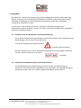
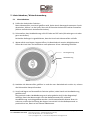
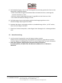
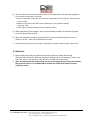
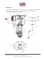
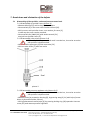
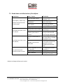
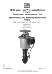
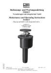
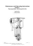
1
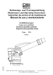
Bedienungs‐ und Wartungsanleitung PERROT Versenkregner mit integriertem Ventil Maintenance and Operating Instructions PERROT Pop‐up sprinkler with integrated valve ZW99551 LVZE 22‐1 VAC LVZE 22‐1 WVAC LVZE 22‐1 WDVAC TDP018 d+e.doc Rev. 29.10.2013 Perrot REGNERBAU CALW GmbH Industriestrasse 19‐29 / D‐75382 Althengstett / Germany Phone: +49‐7051‐162‐0 / Fax : +49‐7051‐162–133 E‐mail :[email protected] / E‐mail Technical Department: [email protected] Seite / Page 1 / 24 Inhalt 1. 2. 3. 4. 5. 6. 7. Allgemeines Sicherheit Beschreibung Montage Inbetriebnahme / Winterfestmachung Wartung Betriebsstörung und Behebung 1. Allgemeines Wir gehen davon aus, dass Sie sich auf dem Gebiet der Beregnung auskennen. Deshalb haben wir diese Anleitung kurzgefasst und nur diejenigen Informationen hineingebracht, die Sie im Hinblick auf die Verwendung dieses Produktes unbedingt erhalten müssen. Gewährleistung kann nur übernommen werden, wenn der Regner unter Beachtung dieser Betriebsanleitung betrieben wurde und innerhalb der Garantiezeit Mängel aufweist. 1.1. Verwendungszweck Der Regner wird zur gleichmäßigen Verteilung von Wasser eingesetzt. Das Wasser sollte vorgereinigt sein, frei von grober und langfasriger Verschmutzung. Max. Wassertemperatur beträgt 50°C. Max. Umgebungstemperatur beträgt 75°C. TDP018 d+e.doc Rev. 29.10.2013 Perrot REGNERBAU CALW GmbH Industriestrasse 19‐29 / D‐75382 Althengstett / Germany Phone: +49‐7051‐162‐0 / Fax : +49‐7051‐162–133 E‐mail :[email protected] / E‐mail Technical Department: [email protected] Seite / Page 2 / 24 2. Sicherheit Diese Betriebs‐ und Sicherheitsanleitung enthält grundlegende Hinweise, die bei Montage, Betrieb, Wartung und Instandsetzung zu beachten sind. Daher ist diese Betriebsanleitung unbedingt vor Montage und Inbetriebnahme vom Monteur sowie dem zuständigen Fachpersonal / Betreiber zu lesen. Es sind nicht nur die in diesem Abschnitt ”Sicherheit” aufgeführten allgemeinen Sicherheitshinweise zu beachten, sondern auch die in den anderen Abschnitten eingefügten speziellen Sicherheitshinweise. 2.1. Kennzeichnung von Hinweisen in der Betriebsanleitung Die in dieser Betriebsanleitung enthaltenen Sicherheitshinweise, deren Nichtbeachtung Gefährdungen von Personen hervorrufen kann sind mit dem allgemeinen Gefahrensymbol besonders gekennzeichnet. Bei Sicherheitshinweisen, deren Nichtbeachtung Gefahren für den Regner und dessen Funktion hervorrufen kann, ist das Wort eingefügt. 2.2. Gefahren bei Nichtbeachtung der Sicherheitshinweise Die Nichtbeachtung der Sicherheitshinweise kann sowohl eine Gefährdung von Personen als auch von Umwelt und Maschine zur Folge haben. Die Nichtbeachtung der Sicherheitshinweise kann zum Verlust jeglicher Schadensansprüche führen. TDP018 d+e.doc Rev. 29.10.2013 Perrot REGNERBAU CALW GmbH Industriestrasse 19‐29 / D‐75382 Althengstett / Germany Phone: +49‐7051‐162‐0 / Fax : +49‐7051‐162–133 E‐mail :[email protected] / E‐mail Technical Department: [email protected] Seite / Page 3 / 24 3. Beschreibung Empfohlener Betriebsdruck 5 bis 6 bar Zulässiger Betriebsdruck 3 bis 8 bar Der Druck am Regner darf 10bar nicht übersteigen Weitere Daten siehe separates Datenblatt 4. Montage Vor Montage der Regner die Leitungen sorgfältig spülen Gewindeanschluss am Regner ist 1“ IG Zur Gewindeabdichtung Hanf und Dichtungsmasse z.B. Fermit Spezial verwenden. Einbau der Regner sollte gemäß „Einbauschema für Versenkregner PERROT LVZE 22 VAC“ erfolgen (siehe nächste Seite). Damit Auflastdrücke auf das Leitungsrohr vermieden werden, ist auf jeden Fall ein Regnergelenk zu verwenden. Der Einbau einer Sickerpackung, wie im Einbauschema gezeigt, wird dringend empfohlen. Die Verbindung der Steuerkabel darf nur mit zugelassenen wasserdichten Verbindungen ausgeführt werden. Aufschrauben des Regners auf das Regnergelenk durch Festhalten am Gehäuserand oder durch Einsatz eines Bandschlüssels. Nicht mit Rohrzange die Steuerleitung am Regner quetschen TDP018 d+e.doc Rev. 29.10.2013 Perrot REGNERBAU CALW GmbH Industriestrasse 19‐29 / D‐75382 Althengstett / Germany Phone: +49‐7051‐162‐0 / Fax : +49‐7051‐162–133 E‐mail :[email protected] / E‐mail Technical Department: [email protected] Seite / Page 4 / 24 Einbauschema für Versenkregner / Installation layout for pop‐up sprinkler PERROT LVZE 22 (W/VAC) PE‐Hauptleitung / dia Main Pipe Pos. 1 2 3 4 Benennung T‐Stück 90° 40 x 1" IG T‐Stück 90° 50 x 1½“ IG T‐Stück 90° 63 x 1½“ IG T‐Stück 90° 75 x 2½“ IG Reduziernippel Nr.241 1½"x1" Reduziernippel Nr.241 2½" x 1" Regnergelenk 1" Anschlusskupplung 40 x 1“ IG Anschlusskupplung 50 x 1½“ IG Anschlusskupplung 63 x 1½“ IG Anschlusskupplung 75 x 2½“ IG Description T‐piece 90° 40 x 1" FT T‐piece 90° 50 x 1½“ FT T‐piece 90° 63 x 1½“ FT T‐piece 90° 75 x 2½“ FT Red.‐Nipple Nr.241 1½" x 1" Red.‐Nipple Nr.241 2½" x 1" Swing Joint 1" Clamp fitting 40 x 1“ FT Clamp fitting 50 x 1½“ FT Clamp fitting 63 x 1½“ FT Clamp fitting 75 x 2½“ FT Teile Nr. Article No. ZH90149 ZH90151 ZH90153 ZH90157 ZK94343 ZK94358 ZH90306 ZH90083 ZH90087 ZH90088 ZH90091 Schema A 40 1 1 50 1 1 1 Schema B 63 1 1 1 75 1 1 1 40 1 1 21.12.2000 kd 50 1 1 1 63 1 1 1 75 1 1 1 Einbauschema Nr. 5 TDP018 d+e.doc PERROT LVZE 22 (W/VAC) Erstellt: Rev. 29.10.2013 Perrot REGNERBAU CALW GmbH Industriestrasse 19‐29 / D‐75382 Althengstett / Germany Phone: +49‐7051‐162‐0 / Fax : +49‐7051‐162–133 E‐mail :[email protected] / E‐mail Technical Department: [email protected] Rev: 19.03.2013 Seite / Page 5 / 24 5. Inbetriebnahme / Winterfestmachung 5.1 Inbetriebnahme a) Prüfen der elektrischen Funktion : Bevor Wasserzufuhr zum Ventil geöffnet wird, Spule mittels Steuergerät ansteuern. Durch akustisches „Klicken“ an der Spule, lässt sich die korrekte elektrische Funktion feststellen. (Klicken entsteht durch Anziehen des Ankers). b) Sicherstellen, dass Handbedienung auf AUTO oder auf OFF steht (Schraube ganz rein oder ganz raus drehen). Bei beiden Stellungen ist gewährleistet, dass das Ventil nach Wasserzufuhr schließt. c) Wasserzufuhr zum Regner langsam öffnen, bis Betriebsdruck ansteht. Möglicherweise öffnet das Ventil kurz und sollte dann nach spätestens 30 sec. selbsttätig schließen. Druckregulierung Handbedienung Bild 1 d) Nachdem die Wasserzufuhr geöffnet ist und der max. Betriebsdruck erreicht ist, müssen alle Dichtstellen überprüft werden. e) Ventil und Regner auf einwandfreie Funktion prüfen, indem Ventil mit Handbedienung geöffnet wird. Das geschieht indem Handbedienung nach rechts gedreht wird, bis der Regnerkopf aufsteigt. Damit der Wasserstrahl nicht das Bedienpersonal trifft, sollte die Handbedienung vorsichtig geöffnet werden. Am herausquellenden Wasser lässt sich erkennen, welche Sprührichtung der Regner hat und wie sich das Bedienpersonal zu positionieren hat, damit es kein Wasser abbekommt. TDP018 d+e.doc Rev. 29.10.2013 Perrot REGNERBAU CALW GmbH Industriestrasse 19‐29 / D‐75382 Althengstett / Germany Phone: +49‐7051‐162‐0 / Fax : +49‐7051‐162–133 E‐mail :[email protected] / E‐mail Technical Department: [email protected] Seite / Page 6 / 24 f) Bei laufendem Regner, kann an der Druckregulierschraube der gewünschte Druck an der Regnerdüse eingestellt werden. Stellt man die Druckregulierschraube auf den minimalen Druck ein, so beträgt der Druck an der Düse ca. 3 bar. Bei einer vollen Umdrehung Richtung (+) vergrößert sich der Druck um 1 bar. Der ideale Betriebsdruck beträgt ca. 6 bar. g) Bei Sektorregner kann im Betrieb der gewünschte Beregnungssektor an den Sektoranschlägen [18] eingestellt werden. h) Nachdem der Regner vollständig entlüftet ist, Handbedienung auf Pos. „AUTO“ stellen, dann muss der Regner schließen. i) Elektrische Funktion überprüfen, indem Regner über Steuergerät ein‐ und ausgeschaltet wird. 5.2 Winterfestmachung Vor Eintritt der Frostperiode, muss der Regner entleert werden. Hierfür muss am Leitungsnetz ein leistungsstarker Kompressor angeschlossen werden. Ventil am Regner so lange geöffnet lassen, bis aus der Regnerdüse nur noch Luft austritt. Nach dem Ausblasen, Magnetspule mehrmals elektrisch ansteuern. Es wird empfohlen, die Spule über die Winterzeit 2/Woche für ca. 1 Minute zu aktivieren. TDP018 d+e.doc Rev. 29.10.2013 Perrot REGNERBAU CALW GmbH Industriestrasse 19‐29 / D‐75382 Althengstett / Germany Phone: +49‐7051‐162‐0 / Fax : +49‐7051‐162–133 E‐mail :[email protected] / E‐mail Technical Department: [email protected] Seite / Page 7 / 24 6. Wartung Innenraum von Regnergehäuse mit Industriesauger oder ähnlichem Gerät reinigen. Regnergehäuse von überwachsendem Gras freistechen. Diese Arbeiten sollten Sinnvollerweise vor der Frühjahrsinbetriebnahme durchgeführt werden. Bild 2 TDP018 d+e.doc Rev. 29.10.2013 Perrot REGNERBAU CALW GmbH Industriestrasse 19‐29 / D‐75382 Althengstett / Germany Phone: +49‐7051‐162‐0 / Fax : +49‐7051‐162–133 E‐mail :[email protected] / E‐mail Technical Department: [email protected] Seite / Page 8 / 24 7. Betriebsstörungen + Behebungen 7.1 Demontage von Regner, Ventil und Drucksteuereinheit 7.1.1 Ausbau des Regnereinsatzes (Bild 2) Blindkappe [1] mit spitzem Gegenstand entfernen. Sechskantschraube [2] im Deckel mit Steckschlüssel [20] herausschrauben. Deckel mit Regnereinsatz hochziehen, Haltesteg [3] wegschwenken, dadurch kann Deckel abgenommen werden. Sechskantschrauben (4x) SW10 [43] mit Steckschlüssel [21] herausdrehen und Regnereinsatz [5] herausziehen. 7.1.2 Ausbau Ventilkolben (Bild 2+3) Bevor nachfolgend beschriebene Arbeiten ausgeführt werden, muss sichergestellt sein, dass Regner drucklos ist. Ventiloberteil [6] mit Ventilheber [22] herausschrauben Ventilkolben [7] mit Ventilheber herausziehen. Dichtmanschette Bild 3 7.1.3 Ausbau der Drucksteuereinheit (Bild 2+5) Bevor nachfolgend beschriebene Arbeiten ausgeführt werden, muss sichergestellt sein, dass Regner drucklos ist. Deckel [8] von Schutzgehäuse nach oben abnehmen, indem Schnapphaken [11] mit Schraubendreher nach außen gedrückt wird. (Ansicht X) Steuerleitung [9] nach unten abziehen, indem Klemmring [10] nach oben gedrückt wird. Kreuzschlitzschraube [12] herausdrehen und Drucksteuereinheit abnehmen. TDP018 d+e.doc Rev. 29.10.2013 Perrot REGNERBAU CALW GmbH Industriestrasse 19‐29 / D‐75382 Althengstett / Germany Phone: +49‐7051‐162‐0 / Fax : +49‐7051‐162–133 E‐mail :[email protected] / E‐mail Technical Department: [email protected] Seite / Page 9 / 24 7.2 Zusammenbau des Regners 7.2.1 Regner spülen Wenn sich im Ventil Schmutzteile befunden haben, sollte der Regner vor Zusammenbau gespült werden. Hierzu Spüleinsatz [23] in Regnergehäuse einbauen (siehe Bild 4) und Wasserzufuhr öffnen. Schlauch am Spüleinsatz anschließen, damit Wasser abgeleitet werden kann. Bild 4 7.2.2 Ventileinbau Beachte, dass alle Teile schmutzfrei sind Ventilkolben auf Ventilheber schrauben, Feder [14] nicht vergessen (siehe Bild 3) Dichtmanschette leicht einfetten. Ventilkolben ins Gehäuse einführen. Durch kurzes Auf‐ und Abbewegen Leichtgängigkeit sicherstellen. Ventilheber [22] herausschrauben Ventildeckel [6] auf Ventilheber [22] schrauben und Ventildeckel fest in Gehäuse einschrauben. TDP018 d+e.doc Rev. 29.10.2013 Seite / Page 10 / 24 Perrot REGNERBAU CALW GmbH Industriestrasse 19‐29 / D‐75382 Althengstett / Germany Phone: +49‐7051‐162‐0 / Fax : +49‐7051‐162–133 E‐mail :[email protected] / E‐mail Technical Department: [email protected] 7.2.3 Einbau Drucksteuereinheit Drucksteuereinheit [14] im Schutzgehäuse [15] gemäß Bild 5 einbauen Beide Einschraubanschlüsse [16] in Drucksteuereinheit fest einschrauben (Bild 2) Schutzgehäuse [15] an Regnergehäuse [16] anschrauben. (siehe Ansicht X) Steuerleitung [9] in Einschraubanschlüsse [16] hineinstecken (richtige Position beachten) Längere Steuerleitung in Einschraubanschluss bei der Spule stecken. (linke Seite Ansicht X) Durch Herausziehen der Steuerleitung auf richtige Klemmung prüfen Bild 5 7.2.4 Regner zusammenbauen Regnereinsatz [5] in Führungsgehäuse hineinstecken Befestigungsmuttern [4] über Kreuz festziehen mit Steckschlüssel [21] Regnerkopf [5] hochziehen und fixieren indem langer Schraubenzieher quer durch Schwinghebel gesteckt wird. Deckel [17] auf Schwinghebelachse stecken und Haltesteg [3] in Haltenut einschwenken. Deckel [17] mit Sechskantschraube [2] befestigen und Blindkappe [3] in Schraubenloch drücken. Regnereinsatz [5] an Deckel [17] hochziehen und Schraubenzieher herausnehmen. Deckel loslassen – Achtung schnellt durch Federkraft zurück ins Gehäuse. Regner ist nun vollständig montiert. Nun kann Funktion überprüft werden, wie in Punkt 5.1 beschrieben. TDP018 d+e.doc Rev. 29.10.2013 Seite / Page 11 / 24 Perrot REGNERBAU CALW GmbH Industriestrasse 19‐29 / D‐75382 Althengstett / Germany Phone: +49‐7051‐162‐0 / Fax : +49‐7051‐162–133 E‐mail :[email protected] / E‐mail Technical Department: [email protected] 7.3 Betriebsstörungen und Behebung Störung Ursache Ventil öffnet / schließt nur mit Handöffnung, nicht auf elektr. Steuersignal Ventil öffnet auch mit Handöffnung nicht Spule bzw. Spulensitz verschmutzt Versorgungsspannung zu gering (24VAC/DC) Spule defekt Plunger in Spule sitzt fest Membrane von Kolbenunterteil defekt Steuerwasserausgang an Zylinder von Ventil verstopft Filter für Steuerwasser verschmutzt Ventil schließt auch mit Handsteuerung nicht Leckage in Pfad von Steuerwasser Druckregler auf min. Stellung Zu geringer Druck an Regnerdüse Druckregler verschmutzt Ventil verstopft Behebung Spule ausbauen und reinigen siehe Punkt 7.1.3 Spannungsversorgung und Kabelverbindung prüfen Spulenwiderstand prüfen (Soll ca. 30) Spule tauschen Kolbenunterteil tauschen (siehe Punkt 7.1.2) Steuerleitung aus Einschraubanschluss ausstecken und rückwärts durchblasen Ventilkolben ausbauen und Filter reinigen bzw. wechseln (siehe Punkt 7.1.3) Einschraubanschlüsse, Steuerleitung und Druckregeleinheit auf externe Leckage prüfen und beheben. Druckregelschraube Richtung (+) drehen Druckregeleinheit tauschen Ventil ausbauen und Leitung spülen (siehe Punkt 7.2.1) Wir behalten uns Änderungen nach dem Stand der Technik auch ohne besondere Ankündigung vor. TDP018 d+e.doc Rev. 29.10.2013 Seite / Page 12 / 24 Perrot REGNERBAU CALW GmbH Industriestrasse 19‐29 / D‐75382 Althengstett / Germany Phone: +49‐7051‐162‐0 / Fax : +49‐7051‐162–133 E‐mail :[email protected] / E‐mail Technical Department: [email protected] Contents 1. 2. 3. 4. 5. 6. 7. General Safety Description Assembly Commissioning Maintenance Break‐down and elimination of the defects 1. General We presume that you are experienced in the field of irrigation. Therefore we have kept this instruction as brief as possible, and have included such information only, which you must have for the use of this product. A guarantee can be accepted only, if the sprinkler has been operated in accordance with these instructions, and if the defect occurs within the guarantee period. 1.1. Application The sprinkler is used for the uniform distribution of the water. The water should be pre‐ cleaned, and free of coarse and fibrous impurities. Max. water temperature will be 50 degree C. Max. ambient temperature will be 75 degree C. TDP018 d+e.doc Rev. 29.10.2013 Seite / Page 13 / 24 Perrot REGNERBAU CALW GmbH Industriestrasse 19‐29 / D‐75382 Althengstett / Germany Phone: +49‐7051‐162‐0 / Fax : +49‐7051‐162–133 E‐mail :[email protected] / E‐mail Technical Department: [email protected] 2. Safety These operation and safety instructions include basic remarks and hints for the assembly, installation, operation, maintenance, inspection and repair. For this reason these instructions must be read by the fitter, as well as by the customers authorised staff, prior to the installation and commissioning. Apart from the general safety instructions of this paragraph the special safety instructions included in other paragraphs of these operating instructions have to be observed also. 2.1. Symbols of hints given in these operating instructions The non‐observance of the safety instructions mentioned in these operating instructions can endanger persons, are marked with the general danger symbol especially. Safety instructions which can endanger the sprinkler and its function, if not observed, are specially marked and the word has been inserted. 2.2. Dangers if the safety instructions are not observed Non‐observance of the safety instructions can endanger persons as well as the environment and the sprinkler. Non‐observance of the safety instructions can result in a loss of all claims for indemnity. TDP018 d+e.doc Rev. 29.10.2013 Seite / Page 14 / 24 Perrot REGNERBAU CALW GmbH Industriestrasse 19‐29 / D‐75382 Althengstett / Germany Phone: +49‐7051‐162‐0 / Fax : +49‐7051‐162–133 E‐mail :[email protected] / E‐mail Technical Department: [email protected] 3. Description Recommended operating pressure 5 to 6 bar Permissible operating pressure 3 to 8 bar The pressure at the sprinkler must not exceed 10 bars. For further data please refer to the separate data leaflet. 4. Assembly Flush pipe work thoroughly before assembling Threaded connection on the sprinkler is 1“ female thread. For sealing the thread, hemp and a jointing compound has to be used e.g. Fermit special Installation of the sprinkler should occur according to the “Installation layout for PERROT pop‐up sprinkler LVZE 22 VAC“ (see next side). To avoid burden pressure on the conduit pipe use in any rate a sprinkler swing joint. It is recommended to assemble a gravel package, as shown in the installation layout. The connection of the control cables is only allowed with approved watertight connections. To screw the sprinkler on the swing joint hold on to the housing border or use a strap wrench. Do not pinch control pipe of the sprinkler with pipe wrench. TDP018 d+e.doc Rev. 29.10.2013 Seite / Page 15 / 24 Perrot REGNERBAU CALW GmbH Industriestrasse 19‐29 / D‐75382 Althengstett / Germany Phone: +49‐7051‐162‐0 / Fax : +49‐7051‐162–133 E‐mail :[email protected] / E‐mail Technical Department: [email protected] Einbauschema für Versenkregner / Installation layout for pop‐up sprinkler PERROT LVZE 22 (W/VAC) PE‐Hauptleitung / dia Main Pipe Pos. 1 2 3 4 Benennung T‐Stück 90° 40 x 1" IG T‐Stück 90° 50 x 1½“ IG T‐Stück 90° 63 x 1½“ IG T‐Stück 90° 75 x 2½“ IG Reduziernippel Nr.241 1½"x1" Reduziernippel Nr.241 2½" x 1" Regnergelenk 1" Anschlusskupplung 40 x 1“ IG Anschlusskupplung 50 x 1½“ IG Anschlusskupplung 63 x 1½“ IG Anschlusskupplung 75 x 2½“ IG Description T‐piece 90° 40 x 1" FT T‐piece 90° 50 x 1½“ FT T‐piece 90° 63 x 1½“ FT T‐piece 90° 75 x 2½“ FT Red.‐Nipple Nr.241 1½" x 1" Red.‐Nipple Nr.241 2½" x 1" Swing Joint 1" Clamp fitting 40 x 1“ FT Clamp fitting 50 x 1½“ FT Clamp fitting 63 x 1½“ FT Clamp fitting 75 x 2½“ FT Teile Nr. Article No. ZH90149 ZH90151 ZH90153 ZH90157 ZK94343 ZK94358 ZH90306 ZH90083 ZH90087 ZH90088 ZH90091 Schema A 40 1 1 50 1 1 1 Schema B 63 1 1 1 75 1 1 1 40 1 1 21.12.2000 kd 50 1 1 1 63 1 1 1 75 1 1 1 Einbauschema Nr. 5 TDP018 d+e.doc PERROT LVZE 22 (W/VAC) Rev. 29.10.2013 Erstellt: Rev: 19.03.2013 Seite / Page 16 / 24 Perrot REGNERBAU CALW GmbH Industriestrasse 19‐29 / D‐75382 Althengstett / Germany Phone: +49‐7051‐162‐0 / Fax : +49‐7051‐162–133 E‐mail :[email protected] / E‐mail Technical Department: [email protected] 5. Commissioning / Winterise 5.1 Commissioning a) Check of electrical function : Before the water supply to the valve is opened, the coil has to be triggered through a control unit. Through an acoustic “click” on the coil, the correct electrical function can be determined. (The click arises through attracting the relay armature.) b) Make sure that the manual operation stands on AUTO or OFF (Turn screw totally in or out). In both positions it is warrant that the valve closes after the water supply. c) Open water supply to the sprinkler slowly. Probably the valve opens for a short time, but after 30 sec. it should close on its own. Pressure regulation Manual operation picture 1 d) After opening the water supply and after the max. working / operation pressure is reached, every seal has to be checked / examined. e) Check valves and sprinkler for perfect function, when opening the valve manual. That can be executed by turning the manual operation to the right, until the sprinkler head pops up. So that the water jets do not hit the operator, the manual operation should be opened carefully. You can see the spray direction of the sprinkler on the out gushing water and so the operator can see where he has to stay for not getting wet. TDP018 d+e.doc Rev. 29.10.2013 Seite / Page 17 / 24 Perrot REGNERBAU CALW GmbH Industriestrasse 19‐29 / D‐75382 Althengstett / Germany Phone: +49‐7051‐162‐0 / Fax : +49‐7051‐162–133 E‐mail :[email protected] / E‐mail Technical Department: [email protected] f) The desired pressure on the sprinkler nozzle can be adjusted on the pressure regulation screw while the sprinkler is working. If on the sprinkler nozzle the min. pressure is adjusted, there is approx. 3 bar pressure on the nozzle. When turning the screw 360° once in direction (+) the pressure always raises up 1 bar. The perfect / ideal working pressure is approx. 6 bars. g) While operation of the sprinkler, there is the possibility to adjust the desired irrigation sector on the spring stop [18]. h) After the complete ventilation of the sprinkler the manual operating must be set on position „AUTO“ , than the sprinkler have to close. i) Check electrical function by turning on and off the sprinkler with help of a control unit. 5.2 Winterise Before beginning of the frost period the sprinkler has to be totally drained off. Therefore there must be connected a powerful compressor on the network / main circuit. Open the valve on the sprinkler until only air is coming out of the nozzle. After the blowing out the magnetising coil has to be triggered electrically several times. During winter time it is recommended to activate the solenoid for about 1 minute 2 times per week. TDP018 d+e.doc Rev. 29.10.2013 Seite / Page 18 / 24 Perrot REGNERBAU CALW GmbH Industriestrasse 19‐29 / D‐75382 Althengstett / Germany Phone: +49‐7051‐162‐0 / Fax : +49‐7051‐162–133 E‐mail :[email protected] / E‐mail Technical Department: [email protected] 6. Maintenance Clean interior space of the sprinkler with an industrial type vacuum cleaner or a similar device. Clean / Relieve sprinkler housing from overgrown grass. This work should be done conveniently before commissioning in spring. picture 2 TDP018 d+e.doc Rev. 29.10.2013 Seite / Page 19 / 24 Perrot REGNERBAU CALW GmbH Industriestrasse 19‐29 / D‐75382 Althengstett / Germany Phone: +49‐7051‐162‐0 / Fax : +49‐7051‐162–133 E‐mail :[email protected] / E‐mail Technical Department: [email protected] 7. Break‐down and elimination of the defects 7.1 Dismantling of the sprinkler, valve and pressure control unit 7.1.1 Disassembly of sprinkler insert (picture 2) Remove blind cap [1] with a sharp pointed object. Unscrew bolt [2] in the cover with a socket wrench [20]. Pull up cover with sprinkler insert, turn retainer for cover [3], In that way the cover can be removed. Unscrew bolt (4x) SW10 [43] with socket wrench [21] and pull out sprinkler insert [5]. 7.1.2 Disassembly valve piston (picture 2+3) Before the following mentioned work is carried out, it must be sure that the sprinkler is depressurised. Unscrew valve upper part [6] with ram valve [22] Pull out valve insert [7] with ram valve. Seal picture 3 7.1.3 Disassembly pressure regulator unit (picture 2+5) Before the following mentioned work is carried out, it must be sure that the sprinkler is depressurised. Remove cover for protection housing [8], by pressing snap fit [11] with help of screw driver in direction outside. (View X) Pull off downwards control pipe [9], by pressing locking ring [10] upwards. Unscrew screw [12] and remove pressure regulator. TDP018 d+e.doc Rev. 29.10.2013 Seite / Page 20 / 24 Perrot REGNERBAU CALW GmbH Industriestrasse 19‐29 / D‐75382 Althengstett / Germany Phone: +49‐7051‐162‐0 / Fax : +49‐7051‐162–133 E‐mail :[email protected] / E‐mail Technical Department: [email protected] 7.2 Assembling of the sprinkler 7.2.1 Flush sprinkler In case that the valve contains soil particles, the sprinkler has to be flushed before assembling. Assemble flushing equipment [23] in the sprinkler housing (see picture 4) and open water supply. Connect hose on flushing equipment, so that water can be derived. picture 4 7.2.2 Assembly valve Take care that all pieces are clean. Screw on valve insert on valve ram, do not forget spring [14] (see picture 3) Grease seal slightly. Feed / introduce valve piston in the housing. Examine facility by slight up and down movements. Unscrew valve ram [22] Screw valve cover [6] on valve ram [22] and screw in tight into housing. TDP018 d+e.doc Rev. 29.10.2013 Seite / Page 21 / 24 Perrot REGNERBAU CALW GmbH Industriestrasse 19‐29 / D‐75382 Althengstett / Germany Phone: +49‐7051‐162‐0 / Fax : +49‐7051‐162–133 E‐mail :[email protected] / E‐mail Technical Department: [email protected] 7.2.3 Assembly pressure control unit Assembly pressure regulator [14] in the protection housing [15] according picture 5. Screw in tight both screw connections [16] in protection housing (picture 2) Screw in protection housing [15] on sprinkler housing [16]. (see view X) Plug in control pipe [9] in screw connections [16] (Attention! Take care of the right position). Plug in longest control pipe in the screw connection at the coil side. (Left side, view X) Examine right clamping by drawing control pipe. picture 5 7.2.4 Sprinkler assembly Plug in sprinkler insert [5] in guide housing Tighten fixing nuts [4] crosswise with socket wrench [21] Pull up sprinkler insert [5] and fix it, by plugging a long screw driver diagonally through impact lever. Plug in cover [17] on impact lever axle and turn retainer for cover [3] in slot. Fasten cover [17] with bolt [2] and press blind cap [3] in screw hole. Pull up sprinkler insert [5] on the cover [17] and take screwdriver away. Let go off the cover – Attention! Bounces because of elastic force back to the housing. The sprinkler is now completely assembled. Now the function can be checked as described under point 5.1. TDP018 d+e.doc Rev. 29.10.2013 Seite / Page 22 / 24 Perrot REGNERBAU CALW GmbH Industriestrasse 19‐29 / D‐75382 Althengstett / Germany Phone: +49‐7051‐162‐0 / Fax : +49‐7051‐162–133 E‐mail :[email protected] / E‐mail Technical Department: [email protected] 7.3 Break‐down and elimination of the defects Break down Valve opens / closes only manual not by electrical, Control signal Valve does not open, even not manual Valve does not close, even not manual, The pressure on the sprinkler nozzle is to low. Cause / reason Elimination Remove coil and clean it, Coil or coil seat is dirty see point 7.1.3 Supply voltage is to low Check supply voltage and (24VAC/DC) cable connections Check coil resistance Coil is broken (must be approx. ca. 30) Plunger in coil is seated Change coil Change valve insert (see Seal of valve insert is defect point 7.1.2) Control water exit on Disassembly control pipe cylinder of the valve is out off connection and blocked blow through backwards Disassembly valve insert Filter for control water is and clean filter or change it dirty (see point 7.1.3) Check all connections, control pipe and pressure Leakage in the control regulators units for water path leakages and eliminate them. Pressure regulator is set on Turn adjustment screw in min. position. direction (+) Pressure regulator is dirty Change pressure regulator Disassembly valve and Valve is blocked flush pipes (see point 7.2.1) Subject to change without prior notice. TDP018 d+e.doc Rev. 29.10.2013 Seite / Page 23 / 24 Perrot REGNERBAU CALW GmbH Industriestrasse 19‐29 / D‐75382 Althengstett / Germany Phone: +49‐7051‐162‐0 / Fax : +49‐7051‐162–133 E‐mail :[email protected] / E‐mail Technical Department: [email protected] Für weitere Informationen stehen wir Ihnen gerne zur Verfügung. We remain at your full disposal for any further information you may require! ZW99551 REGNERBAU CALW GmbH Industriestrasse 19‐29 75382 Althengstett / Germany Tel. +49 / 7051 / 162‐0 Fax. +49 / 7051 / 162‐133 http://www.perrot.de TDP018 d+e.doc Rev. 29.10.2013 Seite / Page 24 / 24 Perrot REGNERBAU CALW GmbH Industriestrasse 19‐29 / D‐75382 Althengstett / Germany Phone: +49‐7051‐162‐0 / Fax : +49‐7051‐162–133 E‐mail :[email protected] / E‐mail Technical Department: [email protected]