1
E K-TU77 - U G-001
TU77
Magnetic Tape Transport
User's Guide
digital equipment corporation • maynard, massachusetts
1st Edition, February 1979
The drawings and specifications herein are the property of Digital Equipment
Corporation and shall not be reproduced or copied or used in whole or in part
as the basis for the manufacture or sale of equipment described herein without
written permission.
Copyright
©
1979 by Digital Equipment Corporation
The material in this manual is for informational
purposes and is subject to change without notice.
Digital Equipment Corporation assumes no responsibility for any errors which may appear in
this manual.
Printed in U.S.A.
This document was set on DIGITAL's DECset-8000
computerized typesetting system.
The following are trademarks of Digital Equipment Corporation,
Maynard, Massachusetts:
DIGITAL
DEC
PDP
DECUS
UNIBUS
D ECsystem-l 0
DECSYSTEM-20
DIBOL
EDUSYSTEM
VAX
VMS
MASSBUS
OMNIBUS
OS/8
RSTS
RSX
lAS
CONTENTS
Page
CHAPTER 1
GENERAL DESCRIPTION
l.1
l.2
1.3
l.4
1.5
INTRODUCTION .............................................................................................. 1-1
PHYSICAL DESCRIPTION .............................................................................. 1-1
FUNCTIONAL DESCRIPTION ........................................................................ 1-8
APPLICABLE DOCUMENTS ......................................................................... 1-12
MECHANICAL AND ELECTRICAL SPECIFICATIONS ............................. 1-13
CHAPTER 2
INSTALLATION
2.1
2.1.1
2.1.2
2.1.3
2.2
2.2.1
2.2.2
2.3
2.3.1
2.3.2
2.4
2.4.1
2.4.2
2.5
2.5.1
2.5.1.1
2.5.1.2
2.5.1.3
2.5.1.4
2.5.1.5
2.5.1.6
2.5.1.7
2.5.1.8
2.5.2
2.5.2.1
2.5.2.2
2.5.2.3
2.5.2.4
2.5.2.5
SITE PLANNING AND CONSIDERA TIONS .................................................. 2-1
Space Requirements ..................................................................................... 2- )
Power Requirements ................................................................................ , ... 2- )
Environmental Requirements ....................................................................... 2-2
UNPACKING AND INSPECTION ................................................................... 2-2
Unpacking ................................................................................................... 2-2
Inspection .................................................................................................... 2-2
SING LE TRANSPORT INSTALLATION ......................................................... 2-3
Mechanical Installation .......................... , ..................................................... 2-3
Power and Cabling ....................................................................................... 2-5
MULTI-TRANSPORT INSTALLATION .......................................................... 2-7
Mechanical Installation ................................................................................ 2-7
Power and Cabling ............. , ....................................................................... 2-1 0
ACCEPTANCE TESTING ............................................................................... 2-11
Turn-On and Loading Checkout. .............................................. '" ............... 2-13
Power On ........................................................................................... 2-13
Load Sequence Without Tape ............................. , ............................... 2-14
Inhibited Autoload Sequence .............................................................. 2- ) 4
Autoload Sequence ............................................................................. 2-14
Manual Load Sequence ...................................... , ............................... 2-16
Unload Sequence ................................................................................ 2-16
Manual Load Repeatability ................................................................ 2-16
Autoload Repeatability ...................................................................... 2-17
TM03/TU77 Diagnostics ........................................................................... 2-18
Control Logic Test No.1 .................................................................... 2-19
Control Logic Test No.2 .................................................................... 2-19
Basic Function Test ................................................................ , ........... 2-19
Drive Function Timer ......................................................................... 2-19
Data Reliability .................................................................................. 2-19
CHAPTER 3
OPERATION
3.1
3.2
3.2.1
3.2.2
CONTROLS AND INDICATORS ..................................................................... 3-1
OPERATING PROCEDURES ........................................................................... 3-2
Power On-Off ............................................................................................... 3-2
Autoload/Manual Load Selection ................................................................ 3-2
iii
CONTENTS (Coot)
Page
3.2.3
3.2.4
3.2.5
3.2.6
3.2.7
3.2.8
3.2.9
Autoload ...................................................................................................... 3-3
Manual Load ............................................................................................... 3-4
Probable Causes of Load Failure .................................................................. 3-6
Mid-Reel Load ............................................................................................. 3-7
Unload ......................................................................................................... 3-7
Rewind ......................................................................................................... 3-8
On Line/Off Line ......................................................................................... 3-8
CHAPTER 4
CUSTOMER CARE AND PREVENTIVE MAINTENANCE
4.1
4.2
4.3
4.3.1
4.3.2
4.3.3
4.3.4
CUSTOMER RESPONSIBILITIES ................................................................... .4-1
CARE OF MAGNETIC TAPE ........................................................................... 4-1
CUSTOMER PREVENTIVE MAINTENANCE OF TU77
TAPE TRANSPOR T ........................................................................................... 4-2
General ........................................................................................................ 4-2
Preventive Maintenance ............................................................................... 4-2
Magnetic Tape Transport Cleaning Kit ........................................................ 4-2
Cleaning the TU77 Tape Transport ............................................................. .4-3
APPENDIX A
GLOSSARY
FIGURES
Figure No.
1-1
1-2
1-3
1-4
1-5
1-6
1-7
2-1
2-2
2-3
2-4
2-5
2-6
2-7
2-8
2-9
2-10
2-11
Title
Page
Basic System Configuration .................................................................................. 1-1
TU77 Master Tape Transport ............................................................................... 1-2
Base Assembly ..................................................................................................... 1-4
Card Cage Area .................................................................................................... 1-6
Power Pack Assembly; Rear View ........................................................................ 1-7
Possible TU77 Configurations .............................................................................. 1-8
Master TU77 Functional Block Diagram ............................................................. 1-9
Space and Service Clearance, Top View ................................................................ 2-1
Caster Lock Assembly .......................................................................................... 2-2
Location of Stabilizer Arm and Leveler Feet. ........................................................ 2-4
Rear Door Opening Tool ..................................................................................... 2-4
Location ofTM03 Shelf Locking Pins and Power Pack Connector ........................ 2-4
PCB Shipping Bracket .......................................................................................... 2-5
861 B Power Control PaneL ................................................................................... 2-6
Rear of Power Pack with Pulley Cover Removed .................................................. 2-7
Massbus Connection to TU77 Master Transport. ................................................. 2-8
Top Cover Fastener .............................................................................................. 2-9
Corporate Cabinet with Side Panels and Top Cover Removed .............................. 2-9
iv
FIGURES (Coot)
Figure No.
2-12
2-13
2-14
2-15
2-16
2-17
2-18
2-19
3-1
3-2
3-3
3-4
3-5
3-6
4-1
Title
Page
Slave Bus Cabling of TU77 Daisy Chain ............................................................. 2-12
Cable Orientation on M8940 MT A Module ............................................. '" ........ 2-13
Power On ........................................................................................................... 2-13
Load Sequence Without Tape ............................................................................. 2-14
Inhibited Autoload Sequence .............................................................................. 2-14
Autoload Sequence ............................................................................................. 2-15
Manual Load Sequence ...................................................................................... 2-16
Unload Sequence ................................................................................................ 2-17
TU77 Control Panel ............................................................................................. 3-1
Autoload/Manual Load Selection ........................................................................ 3-3
Tape Content Limit .............................................................................................. 3-3
Autoload Sequence with Operator Troubleshooting ............................................. 3-5
Tape Path and Controls ........................................................................................ 3-6
Manual Load Sequence with Operator Troubleshooting ....................................... 3-7
Transport Items for Daily Cleaning ..................................................................... .4-3
TABLES
Table No.
1-1
1-2
2-1
2-2
2-3
3-1
3-2
Title
Page
Applicable Documents ....................................................................................... 1-12
Mechanical and Electrical Specifications ............................................................ 1-13
Primary Power Connections ................................................................................. 2-6
AC Motor Pulley Part Numbers ........................................................................... 2-7
TM03/TU77 Diagnostics Used for Acceptance Testing ...................................... 2-18
TU77 Controls ..................................................................................................... 3-1
TU77 Indicators ................................................................................................... 3-2
v
111111111111111111111111111111111111111111111111
11111I111111111111111111111111111111111111111111
9109-5-A0380
Frontispiece - TU77 Tape T ran sport
CHAPTER 1
GENERAL DESCRIPTION
1.1 INTRODUCTION
The TV77 is a magnetic tape transport that records and reads data in 9-track non-return-to-zero
(NRZI) or phase-encoded (PE) format. Bit density is 800 bits per inch (BPI) for the NRZI format and
1600 BPI for the PE format. The transport can read data in the forward or reverse direction. The
read/write tape speed for both the forward and reverse directions is 125 inches per second (IPS). The
nominal rewind time for a 731.5 m (2400 ft) reel is 65 seconds.
rTU77 MASTER TRANSPORT
-
-
-
-
-
-
I (TM03/TAPE TRANSPORT)
1,...-----....,
CPU •
MASSBUS
•
CONTROLLER
TAPE
TRANSPORT
TO 1-7
*1.
2.
3.
PDP-11 & RH11
DECsystem 20 (KL 10 & RH20)
PDP-111780 VAX
OTHER
TM03
FORMATTERS
Figure 1-1
-,
I
TO 1-3
OTHER
TRANSPORTS
Basic System Configuration
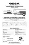
The TV77 transport interfaces with the system processor via the Massbus, a Massbus controller and a
TM03 tape formatter. Vp to four TV77s may be driven from one TM03 formatter. Figure 1-1 illustrates the basic system configuration for a TV77. The TM03 tape formatter and its associated power
supply (H740-DA) are housed in the TV77 cabinet (H9500* corporate cabinet). Those TV77s containing a TM03 are designated as "master units". TV77s without the TM03 are the "slave units".
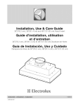
1.2 PHYSICAL DESCRIPTION
Figure 1-2 illustrates the locations of the major subassemblies of the TV77. These are:
TM03 tape formatter (master TU77 only)
H740-DA power supply (master TU77 only)
861 power control
TU77 transport, consisting of:
Base assembly
Card Cage Area
Power Pack Assembly
*The specific model of the H9500 cabinet series used for the TU77 is H9602KA, however, the cabinet is referred to as the H9500 in this
manual.
1-1
BASE ASSEMBLY
TM03 TAPE
FORMATIER
POWER
PACK
ASSEMBLY
B61 POWER CONTROL
Figure 1-2
a. Front View
TU77 Master Tape Transport
1-2
CARD CAGE
(REAR VIEW)
EXHAUST FANS (2)
~ ....
BLOWER
MOTOR
PULLEY
COVER
H740-DA
POWE R SUPP L Y
~--
~_v_v
MA-2648
Figure 1-2
b. Rear View
TU77 Master Tape Transport
1-3
CARTRIDGE
REEL HUB
ASSEMBLY
REEL SENSE
ASSEMBLY
TIP
~-r~r-Itt--~----~~~JL
HEAD
MA-2636
a. Front View
Figure 1-3 Base Assembly
Figure 1-3 is a front and rear view of the base assembly identifying components within the assembly.
These are:
Control assembly (P.N. 29-23214)
Reel sense assembly (P.N. 29-23216)
Autoload interlock switch (P.N. 29-23297)
Reel hub assembly (P.N. 29-22776)
Buffer box door assembly (P.N. 29-23215)
Tape in path (TIP) assembly (P.N. 29-23243)
EOT jBOT assembly-(P.N. 29-23242)
Head (P.N. 29-23233)
Cartridge interlock switch (P.N. 29-16280)
Upper restraint (P.N. 29-23225)
Lower restraint (P.N. 29-23224)
1-4
PRESSURE VALVE
ASSEMBLY
PRESSURE
SWITCH
(COLUMN LIMIT)
WRITE PROTECT
ASSEMBLY
CARTRIDGE
MOTOR
VACUUM
TRANSDUCER
ASSEMBLY
'J-.rm.~~~.-::s:::;;;;=~~H~ VACUUM VALVE
ASSEMBLY
PREAMP PCB
SERVICE
LOCK
CAPSTAN MOTOR
ASSEMBLY
PACK SENSE ASSEMBLY
(NOT SHOWN)
REEL MOTOR ASSEMBLY
(TAKE-UP REEL)
MA-2664
b. Rear View
Figure 1-3 Base Assembly
Cartridge motor (P.N. 29-23280)
Pressure switch (Pneumatic interlock) (P.N. 29-23240)
Pressure valve assembly (P.N. 29-23249)
Interconnect F 1 printed circuit board (PCB) (P.N. 29-23213)
Reel motor assemblies (2) (P.N. 29-23236)
Write protect assembly (P.N. 29-23235)
Vacuum valve assembly (P.N. 29-23248)
Pressure switches (vacuum) (2) (P.N. 29-23238, 29-23239)
Pack sense assembly (P.N. 29-23217)
Capstan motor assembly (P.N. 29-23234)
Service lock
Preamp printed circuit board (PCB) (P.N. 29-23232)
Vacuum transducer assembly (P.N. 29-23246)
Pressure switch (column limit) (P.N. 29-23238)
1-5
EXHAUST FANS (2)
MTA PCB
I
I
DATA L PCB
WRITE PCB
CAPSTAN SE RVO
PCB
REEL SEHVO PCB
Figure 1-4
BLOWER MOTOR
MA-2644
Card Cage Area
Figure 1-4 illustrates the card cage area containing the following items :
Magtape adapter (MTA) M8940 PCB (P.N. M8940)
Data L PCB (P.N. 29-23227)
Write PCB (P.N. 29-23226)
Control M PCB (P.N. 29-23229)
Capstan/regulator PCB (P.N. 29-23230)
Reel servo PCB (P.N. 29-23231)
Blower motor (P.N. 70-14569)
Exhaust fans (2) (P.N. 12-10930)
Interconnect 01 PCB (interconnecting backplane not shown in Figure 1-4) (P.N. 29-23211)
1-6
COMPRESSOR
RECTIFIERS (3)
TRANSFORMER
MOTOR
(UNDER COVER)
BLOWER
PULLEY COVER
Figure 1-5
Power Pack Assembly; Rear View
Figure 1-5 illustrates the power pack assembly containing the following items:
Rectifiers (3) (Part Numbers 29-23311, 29-23312)
Vacuum hose
Fuse panel
Air filter (P.N. 29-23259)
Blower (P.N. 29-23253)
Pulley cover
Power transformer terminal strip
Compressor (P.N. 29-23257)
Motor (P.N. 29-23254)
Transformer (P.N. 29-23258)
1-7
MA 2643
r:----------~
~~~:
MASSBUS
CONTROLLER
°0 ~~
FORMATTER
NO.O
IL
TU77
.,M,A.§I.ElL _ _
__
~7~~
II
J I
-'
TU77 NO. n
(n = 1 TO 3)
rr;;03---------=;-]
I
g
~~ I
_______
~~:~::~:I
TU77
L~S~
TU77 NO. 0
I
:.1
TU77 NO. n
(n =
1 TO 3)
MA-2642
Figure 1-6
Possible TU77 Configurations
1.3 FUNCTIONAL DESCRIPTION
Figure 1-6 illustrates the various TV77 configurations that are possible from the Massbus. The TM03
tape formatter interfaces up to four TV77 transports to the Massbus. Additional TM03s may be
added, up to a maximum of eight, with each formatter interfacing up to four additional TV77s. Thus
the maximum configuration interfacing a Massbus controller consists of eight TM03 formatters and 32
TV77 transports.
The TM03 tape formatter is housed in the TV77 cabinet. Those TV77 cabinets containing a TM03
(and its associated H740-DA power supply) are designated as master transports while those without
the TM03 and H740-DA are designated as slave transports. The basic transport within a TV77 master
is identical to a TV77 slave transport.
Figure 1-7 is a functional block diagram of a master TV77 tape transport. During a write operation the
TM03 accepts write data from the Massbus and formats it into 8-bit data characters for the TV77
transport. Massbus data is in PDP-I0 compatible, PDP-I0 core dump, PDP-ll normal or PDP-iS
normal format. The TM03 disassembles the Massbus data under control of the CPV which specifies
the format of the data. During a read operation, 8-bit characters received from the transport are
1-8
r;;;;s;Q;T- - - -- -- -- -- -- - - -- -- -- -- -- - -
REMOTE
SWITCHING
CONTROL BUS
FROM CPU
-
POWER
CONTROL
~I POWER
AC LINE
COOLING
FANS
REGULATED DC
SUPPLY AND
DISTRIBUTION
SUPPLY SERVO FEEDBACK
(3)
SUPPLY
PRESSURE
TRANSDUCER
AC LINE
AUTOLOAD
r - - - - - - , I MOTION
H740-DA
POWER
SUPPLY'
COMMANDS
•
+5V
+15V
-15V
DC LO
AC LO
1
\0
CONTROL
LOGIC &
MANUAL
CONTROLS
LIMIT
I
SUPPLY
SUPPLY
LIMIT
SWITCH
REEL
DRIVE
WRITE DATA
READ/WRITE
TO ERASE HEAD
TO WRITE HEAD
READ DATA
SUB SYSTEM
FROM READ HEAD
AUTOLOAD
MOTION
COMMANDS ITAKE-UP REELI. TAKE-UP SERVO FEEDBACK
TM03
I TAPE
1
FORMATIER
MOTION
COMMANDS
_____~.
•
TO OTHER
TU77's
* *-TAKE-UP PRESSURE TRANSDUCER
SERVO
SUB SYSTEM
LIMIT
-
* MASTER TU77 ONLY
~
I SUPPLY REEL
VAC/
PRES
MTA
M8940
READ DATA
CONTROL COMMANDS
STATUS SIGNALS
-1
I
J 861
WRITE DATA
- -
I
(POWER ON/OFF)
INPUT POWER
-
I
I
I
IIII X
0
0
0
0
o
TAKE-UP
REEL
L--r---.-....J1 0 RIVE
SUB SYSTEM
0
0
I
SERVO
SUB SYSTEM
I SERVO
CAPSTAN
0
0
e
o
o
o
SUPPLY LOOP
PNEUMATIC
COLUMN
(BUFFER BOX)
CAPSTAN DRIVE
TACHOMETER OUTPUT
VAC/PRES
I
I
CAPSTAN
TACHOMETER
VACUUM
SENSE
PRESSURE
SENSE
L_
CAPSTAN
MOTOR
TAKE-UP LOOP
PNEUMATIC COLUMN
(BUFFER BOX)
FROM BLOWER
~~
1 - ''
1 - - - '- ' - , - ' -. . . . . . . .
FROM COMPRESSOR
__ J
MA-2659
Figure 1-7
Master TU77 Functional Block Diagram
formatted into data words and placed on the Massbus. The TM03 reassembles the data characters into
the Massbus format specified by the CPU. The TM03 writes and reads data in either 800 BPI NRZI or
1600 BPI PE formats.
During a write operation, the TM03 generates a parity bit for each 8-bit data character, written on
tape. The parity bit is added to the data character, thereby providing 9-bit tape characters to the
transport. Error detection is accomplished by parity checks and, during NRZI operation, cyclic redundancy checks (CRC) and longitudinal redundancy checks (LRC). Error detection occurs for both read
and write operations. During a write operation a read-after-write function is performed where the data
just written on tape is read by the TM03 and undergoes error checking. During read operations, the
TM03 can perform error correction of single-track errors in both NRZI and PE. PE single-track
correction occurs automatically while NRZI single-track error correction is under software control
and must be implemented by the program.
The TM03 also controls and monitors tape transport operation. It receives operational commands
from the CPU, and then selects the desired transport and issues functional and motion commands. It
monitors transport operation and provides error and status information to the CPU.
The H?40-DA power supply supplies regulated ± 15 V and +5 Vdc operating voltage for the TM03.
Power-fail signals AC LO and DC LO are also supplied to the TM03.
The 861 power control provides ac power to the transport cabinet. It provides filtering for the ac input
power which is supplied to switched outlets when the remote power on/off line is enabled from the
system processor via the remote switching control bus. There is no power on/off control on the TU??
control panel. Transport power is turned on and off at the system processor. The switched ac is
supplied to the H?40-DA power supply (master TU?? only), the three cabinet cooling fans and the
transport power pack.
The basic TU?? transport contains seven functional areas as shown in Figure 1-? These are:
Capstan servo subsystem
Reel servo subsystem (2)
Pneumatic subsystem
Read/write subsystem
Control logic and manual controls
MT A interface
Power supply and distribution
The capstan servo subsystem controls the speed and direction of tape movement past the read/write
heads. The subsystem is a velocity servo that receives command signals from the control logic specifying forward, reverse or rewind motion. The capstan motor responds with the appropriate velocity.
The capstan tachometer generates a feedback signal proportional to speed. The feedback signal is
summed with the basic command signal to maintain the correct capstan velocity at all times.
The reel servo subsystems control the speed of the tape reels as required to maintain optimum tension
on the tape between the supply and the take-up reels. The supply reel and take-up reel servos are
similar but separate subsystems. The path followed by the tape in either direction between the supply
reel and take-up reel contains two tape loops in the buffer box (supply loop and take-up loop). Each
1-10
loop is separately formed and maintained by a vacuum in conjunction with automatically controlled
reel motor speeds. In effect, the reel servos function to feed tape into and remove tape from the buffer
box at the rate required to maintain the correct loops.
Servo operation is initiated by signals developed within the pneumatic subsystem. The subsystem
senses that the tape loop position has changed as a result of forward or reverse tape motion. Air is
drawn from the closed ends of the two buffer boxes creating a vacuum causing the tape loop to form in
each box. The differential between the positive pressure inside the loop and the relatively negative
pressure at the closed end of the buffer box (outside the loop), maintains the proper tension on the tape
during the tape loaded state.
A separate chamber is located behind each buffer box and is connected to its respective box by a series
of holes. The spacing and arrangement of these holes is such that, if the loop becomes larger, more of
the holes will be exposed to the positive pressure inside the loop, and fewer will be exposed to the lower
pressure area outside the loop. This will cause the pressure in the chamber to rise. Conversely, if the
loop becomes smaller, the pressure in the chamber will decrease.
Pressure transducers are connected to the supply and take-up chambers. The pressure variations are
interpreted by the pressure transducers to provide the supply and take-up servo feedback signals. The
pressure sensitive feedback signals are fed back to the reel servos to adjust the velocity of the reel
motors for the proper loop in the two buffer boxes. The uppermost and lowermost holes in each buffer
column are limit ports. The limit ports connect to supply and take-up limit switches which feed back to
both the take-up and supply servos. Should the tape cross a limit port in either the supply or take-up
columns, a disabling signal is coupled back to the servos, stopping both reel motors before tape damage occurs.
A pneumatic interlock exists which shuts down the capstan servo and the reel servos if a pneumatic
failure is detected. The pneumatic subsystem contains a blower to create the vacuum for the tape
columns, and a compressor to generate pressure for the tape path bearings. Vacuum and pressure are
monitored by sensing devices. If either is lost, the sensing device sends a VAC/PRES signal to the three
servo subsystems, stopping the servo motors and preventing tape damage.
The read/write subsystem processes and transfers data to and from the magnetic tape. The read function processes data picked up from the tape by the read heads and translates the information from the
recorded NRZI or PE format to digital data acceptable to the external controlling circuits. The function includes the read after write capability that permits the formatter to verify the execution of a write
command while writing is in progress. The write function prepares incoming data for recording in
NRZI or PE format and writes the information on the tape in the selected format.
The control logic and manual control circuit interfaces other TU77 subsystems. The control logic
transfers the read/write data to and from the read/write subsystem, and the operational commands to
the capstan servo. During the autoload sequence the logic circuits control the steps of the sequence by
issuing the appropriate commands to the reel servos. Timing of the autoload sequence steps, and other
operational sequences (such as rewind), is controlled and monitored by the control logic. Commands
1-11
generated by the manual controls are processed by the control logic and applied to the appropriate
subsystem. Transport status (e.g., transport selected, on line, EaT, BOT, etc.) is sensed by the control
logic, which modifies the signals to the read/write subsystem and to the servo subsystems accordingly.
The logic illuminates the appropriate control panel indicators to indicate transport status. Transport
status is sent to the TM03 tape formatter via the MT A interface module.
The control and read/write signals are coupled from the slave bus to the transport via the magnetic
tape adapter (MT A) interface module M8940. The M8940 adapts the signals on the slave bus to the
format required by the transport and vice versa. This includes signal gating, latching and timing. The
M8940 also has a test mode capability for troubleshooting and maintenance.
The power supply function includes ac rectification, filtering, dc regulation, and distribution of power
as required to the various subsystems.
1.4 APPLICABLE DOCUMENTS
Table 1.;.11ists documents applicable to the TV77 tape transport.
Table 1-1
Title
Applicable Documents
Document
Number
Description
TM03 Magnetic Tape Formatter User's
Manual
EK-TM03-0P
Description, programming and installation
information of the TM03.
TM03 Magnetic Tape Formatter Maintenance Manual
EK-TM03-TM
Theory of operation, programming information, installation and maintenance of the
TM03.
H740-D Power Supply Maintenance
Manual
DEC-II-H740A-A-D
Theory and maintenance of H740-DA
power supply.
861-A,B,C Power Controller
DEC-OO-H861 A-A-A
Theory and maintenance of 861 power control.
TU77 Magnetic Tape Transport Technical
Manual; Volume 1
EK-ITU77-TM
Schematics and logic prints of TU77.
TU77 Magnetic Tape Transport Technical
Manual; Volume 2
EK-2TU77-TM
Description, installation, operation, theory
and maintenance of TU77.
TU77 Magnetic Tape Transport IPB
EK-TU77-IP
Exploded views and parts lists of TU77
1-12
1.5 MECHANICAL AND ELECTRICAL SPECIFICATIONS
Table 1-2 details the mechanical and electrical specifications of the transport.
Table 1-2 Mechanical and Electrical Specifications
Item
Specification
Tape (computer grade)
Width
Thickness
12.6492 ± 0.0508 mm (0.498 ± 0.002 in)
0.0381 mm (1.5 mil)
Tape tension
2.224 ± 0.139 Newtons (8.0 oz nominal)
Reel diameter (Autoload)
266.7 mm (10.5 in) maximum (Note 1) and easy load cartridge
#1 and #2*
Recording modes
1600 BPI PE
800 BPI NRZI
Magnetic head
Dual stack (with erase head)
Tape speed
3.2 m/s (125 ips)
Instantaneous speed variation
±3 percent
Long term speed variation
± 1 percent
Rewind time for 731.5 m (2400 ft)
65 seconds nominal with 80 seconds maximum
Tape cleaner
Dual-blade type connected to vacuum supply
Interchannel displacement
Read
Write NRZI
Write PE
3.81 ~m (150 ~in) maximum (Note 2)
5.72 ~m (225 ~in) maximum (Note 3)
11.43 ~m (450 ~in) maximum
Start time
Stop time
3.0 ± 0.3 ms
3.0 ± 0.3 ms
Start distance
Stop distance
4.216 ± 0.508 mm (0.166 ± 0.02 in)
4.953 ± 0.508 mm (0.195 ± 0.02 in)
Beginning of tape (BOT) and end of tape (EaT)
Detectors (Note 4)
Photoelectric
Tape creepage
None
Pneumatic interlock
Tape motion disabled when vacuum is lost in vacuum column
Load time
No greater than 10 seconds without a retry, and 20 seconds
with a retry for 10-1/2 inch reels
Unload time
Less than 7 seconds for 10-1/2 inch reels
Write gap to read gap distance
0.381 ± 0.013 em (0.150 ± 0.005 in)
Weight
288 kg (640 Ibs) (Master unit)
Cabinet dimensions
Height
Width
Depth (from face of front door to rear of cabinet)
152.4 em (60.0 in)
67.3 em (26.5 in)
81.9 em (32.3 in)
*Easy Load #1 and #2 are Registered Trademarks of IBM.
1-13
Table 1-2
Mechanical and Electrical Specifications (Cont)
Item
Specification
Operating temperature
(Electronics)
Non-operating temperature
4.44° to 44.0° C (40° to 112° F)
(Note 5)
-45.55° to 71.11°C (-50° to 160° F)
Operating altitude
o to 2134 m (0 to 7000 ft) (Note 6)
Non-operating altitude
15,240 m (50,000 ft) maximum
Power
Volts ac
Frequency
200, 210, 220, 230, 240, 250
(Note 7)
50 ± I or 60 ± I Hz
Kilovolt amp (K VA)
Standby (Loaded)
Start/stop
1.3 KV A maximum (Note 8)
2.1 KVA maximum (Note 8)
Electronics
All silicon
NOTES
I.
177.8 mm (7 in) and 216.0 mm (8.5 in) reels may be used but cannot be autoloaded.
2.
The maximum displacement between any two bits of a character when reading a master tape using the read section of
the read-after-write head.
3.
The maximum displacement between any two bits of a character on a tape written with all ones using the write section
of the read-after-write head.
4.
Approximate distance from detection area to write head gap is 35.6 mm (l.40 in).
5.
For data transfer, the operating temperature is dictatcd by the nature of the tape material.
6.
Operation above 1220 m (4000 ft) requires installation of high altitude pulley and pulley belts in TV77 power pack.
7.
Line variations must be within ± 10 percent.
8.
Slave unit only. Add 625 W for master units.
1-14
CHAPTER 2
INSTALLATION
2.1
SITE PLANNING AND CONSIDERATIONS
2.1.1 Space Requirements
Figure 2-1 illustrates the space and service clearances required for the TV77 cabinet. Adequate space
must be provided to slide the TM03 out of the cabinet for servicing and to open the front and rear
doors on the TV77 Tape Transport.
2.1.2 Power Requirements
The TV77 Tape Transport can be operated from 200-250 Vac, 50/60 Hz with proper connections on
the power chassis. Line voltage should be maintained to within ± 10 percent of the nominal value and
the frequency should not vary more than ±2 Hz.
---
REAR DOOR
~
"" '" \
64.1 em
(25-1/4in)
\
\
{~~4;~}'mr +
\
+
REMOVABLE SIDE PANEL
76.2 em
(30 in)
LEVELER
4 PLACES
l'---r--+
----I
53.3 em
(21 in)
/
~BASEASSEMBLY
/
L -----
Figure 2-1
/
Space and Service Clearance, Top View
2-1
MA·2641
2.1.3 Environmental Requirements
The TU77 transport should be located in an area free of excessive dust and dirt or corrosive fumes and
vapors. To ensure proper cooling, the bottom of the cabinet and the air vents in the front panel and
rear door of the cabinet must not be obstructed. The operating environment should have cool, wellfiltered, humidified air; a temperature range of 15° to 27° C (59° to 80° F); and relative humidity of 40
to 60 percent.
2.2
UNPACKING AND INSPECTION
2.2.1 Unpacking
The TU77 H9500 cabinet comes packed in an extra strong corrugated cardboard container* that
measures approximately 76 cm (30 in) wide, 89 cm (35 in) long and 147 cm (58 in) high. The cabinet is
shipped on its casters which raises the shipping carton about 7 cm (2-3/4 in) off the floor. The casters
are a shock-isolating type, thus eliminating the need for shipping skids. Caster locks are supplied with
each cabinet (Figure 2-2). These locks function to facilitate cabinet movement by preventing two of the
four casters from swiveling. They also assist in providing cabinet stability by restricting the direction of
cabinet movement. These caster locks are mounted with hardware and may be removed when it becomes necessary to allow omni-directional movement during installation. In any case, the locks are to
be removed when the cabinet has been installed at its final destination. The locks are to be stored with
the cabinet and may be used again if the cabinet has to be moved.
WHEEL LOCK ASS'Y
(TYP. BOTH CASTERS
ON ONE SIDE OF
CABINET)
IMPORANT:
BEFORE ASSEMBLING WHEEL
LOCK, PLACE CASTERS AS
SHOWN
11 5613
Figure 2-2
Caster Lock Assembly
To unpack the TU77 from its shipping container, proceed as follows:
1.
2.
3.
Cut the plastic bands around the container.
Cut the tape on the top and sides of the container.
Remove and dispose of the container. (The container is not reuseable.)
2.2.2 Inspection
After unpacking the TU77 transport, inspect it and report any damage to the responsible shipper and
the local DIGITAL sales office. Inspect as follows:
1.
Inspect all switches, indicators and panels for damage.
2.
Open TU77 front door. Depress the upper and lower release buttons and open the buffer box door. Check that
the buffer box door is tightly secured to the cabinet. Inspect for foreign material, loose or damaged components,
and for glass damage.
* Units shipped outside the continental United States have an additional wooden container around the cardboard carton. The side panels of
the container are bolted together.
2-2
2.3
3.
Check the transport for any foreign material that may have lodged in the take-up reel or other moving parts.
4.
Rotate the supply hub and take-up reel. Check for binding and physical damage.
5.
Rotate the capstan. Check for binding and physical damage.
6.
CAUTION
The capstan is fragile. Do not touch the capstan rubber surface
and do not apply pressure to the capstan which might cause it to
deform.
Check tape path for any sharp edges.
7.
Close the buffer box door by pressing the two release buttons using moderate pressure. (The buttons will not
catch if pressed too hard.)
8.
Close the TU77 front door.
SINGLE TRANSPORT INSTALLATION
2.3.1
Mechanical Installation
After the shipping container has been removed and visual inspection has been performed, roll the
transport cabinet into position and proceed as follows.
1.
An array of vertical slots constitute venting in the cabinet front panel. A quick-release latch is located approximately 2.54 cm (l in) behind each end of this array. Insert a thin-bladed tool, such as a small steel rule, into one
of the end slots and push on the latch while simultaneously pulling forward to release one corner of the front
panel. In the same manner, while continuing to pull forward, release the latch at the other end of the array to free
the front panel. Remove the front panel and set it aside. Do not disconnect the ground strap from the panel.
2.
Remove the two leveler pads and four leveler feet that are wrapped in blister wrap and taped to the inside of the
front panel.
3.
Raise the interlock rods on each side of the cabinet. Remove the two stabilizer arms from the stabilizer sleeve
assemblies (Figure 2-3).
4.
Screw the leveler pads into the stabilizer arms.
5.
Raise the interlock rods. Reinsert the stabilizer arms into the stabilizer sleeve assemblies.
6.
Install the leveler feet in the lower corners of the cabinet frame (Figure 2-3).
7.
Using a 1.43 cm (9/16 in) wrench, lower the leveling feet until they make contact with the floor stabilizing the
cabinet.
8.
Using a level, adjust the feet until the cabinet is level.
9.
Extend the two stabilizer arms and lower the leveler pads until they just touch the floor yet can easily slide along
the floor. Do not place any weight on the leveler pads.
to.
Insert an opening tool (Figure 2-4) into the rear door, and turn one-quarter turn in a counter-clockwise direction
and open the door.
11.
Remove the locking pins from the rear of the TM03 shelf slide assembly (Figure 2-5).
12.
Open the transport front door. Using a screwdriver, release the service lock located in the lower right corner of
the base assembly. Swing the base assembly open.
NOTE
The base assembly will not swing open unless the stabilizer arms
are extended (step 9).
2-3
INTERLOCK
ROD
/
r-- ----
I
~_-LEVELER
i §FOOT
11-5612
Figure 2-3
Location of Stabilizer Arm and Leveler Feet
LOCKING
INPUT POWER
CONNECTOR
TO POWER
PACK
SIDE VIEW
END VIEW
MA-2647
Figure 2-4
Rear Door Opening Tool
Figure 2-5
Location of TM03 Shelf Locking Pins
and Power Pack Connector
2-4
MTA PCB
DATA L PCB
WRITE PCB
CONTROL M PCB
PUSH>
CAPSTAN SERVO PCB
REEL SERVO PCB
MA-2645
Figure 2-6
PCB Shipping Bracket
13.
Remove the PCB shipping bracket by pushing in on the lower front and pulling down from underneath (Figure
2-6).
14.
Check seating of PCBs in their sockets.
2.3.2
Power and Cabling
1.
2.
Check TV77 internal cabling as follows:
a.
Power cable from 861 switched outlet to transport power pack (Figure 2-5)
b.
Power cable from 861 switched outlet to cabinet blowers
c.
Power cable from 861 switched outlet to H740-DA power supply
d.
H740-DA power cabling to TM03*
e.
TM03 cabling to Massbus connector panel*
f.
TM03 cabling to the three connectors on the M8940 MTA board. *
Check that the power on/off circuit breaker on the 861 is on and the remote/local switch is set to REMOTE ON
(Figure 2-7).
*See TM03 User's Manual or TM03 Technical Manual for TM03 cabling. The TM03 manuals are listed in Table 1-1.
2-5
REMOTE SWITCHING
BUS JACK (3)
REMOTE/LOCAL
SWITCH
UNSWITCHED
POWER AVAILABLE
INDICATORS (2)
Figure 2-7
POWER ON/OFF
CIRCUIT BREAKER
861 B Power Control Panel
3.
Check fuses on power pack fuse panel (Figure 1-5). To see fuses, it is necessary to fully extend the TM03 shelf.
The fuses can be seen from the front of the cabinet. A closer view can be obtained from the rear of the cabinet by
looking over and down onto the fuse panel.
4.
Remove the cover from the power transformer terminal strip (Figure 2-8). (The ac input plug on the power pack
must also be removed.) Check that the blue, brown and white/red wires are connected to the lower terminals as
shown in Table 2-1. The terminals are numbered 1 through 9 from left to right.
Table 2-1
Primary Power Connections
Input Voltage
Blue Wire
Brown Wire and
White/Red Wire
198 206 216 226 236 246 -
TBl-4
TBl-3
TBl-4
TBI-3
TBI-4
TBl-3
TBI-7
TBl-7
TBI-8
TBI-8
TBl-9
TBI-9
205
215
225
235
245
255
Replace the cover and connect the power pack connector.
5.
Check that the circuit breaker on the rear of the power pack is in the on (up) position.
6.
Remove the pulley cover from the rear of the transport power pack (Figure 2-8) and check that the ac motor
pulley is the proper one for the source frequency and altitude as shown in Table 2-2. The variation of the vendor
part number is stamped on the pulley. Spin the ac motor pulley by hand and check that the blower and compressor belts are tight and track properly. Replace the pulley cover.
7.
Connect the BC06S round Massbus cable to the "in" connector on the rear of the TU77 (Figure 2-9).
8.
Connect a Massbus terminator into the "out"
receptac1e~
POWER TRANSFORMER
TERM INAL STRIP
TERMINAL NO.9
CIRCUIT
MOTOR
PULLEY
MA·2663
Figure 2-8
Rear of Power Pack with Pulley Cover Removed
Table 2-2
Frequency
Altitude*
DEC
Part Number
Vendor
Part Number
60Hz
60Hz
50Hz
50Hz
Low
High
Low
High
29-23299
29-23300
29-23301
29-23302
108478-01
108478-02
108478-03
108478-04
* Low = Under
9.
2.4
AC Motor Pulley Part Numbers
1,220 M (4,000 ft), High
= Over
1,220 M (4,000 ft)
Connect the remote switching control bus from the CPU to one of the three jacks on the 861, next to the
remote/local switch.
10.
Replace the front panel. Close the rear door.
11.
Check that system power is off at the CPU and connect the ac power cable from the 861 to the power source.
12.
Perform the acceptance tests (Paragraph 2.5).
MULTI-TRANSPORT INSTALLATION
2.4.1 Mechanical Installation
When an installation contains more than one transport; only the master transport is shipped with the
side panels. During installation, one of the side panels is removed, and the master and slave transport(s) are bolted together. The removed side panel is then mounted onto the end slave transport.
2-7
BC06S ROUND
MASSBUS CABLE IN
MASSBUS TERMINATOR
70-09938 INSTALLED
IN "OUT" RECEPTACLE
BC06R CAB LES
TOTM03
MA 2646
Figure 2-9
Massbus Connection to TU77 Master Transport
After the shipping containers have been removed and the transports have been visually inspected, roll
the transport cabinets into their approximate position. Place the master transport next to the CPU.
Proceed as follows for each cabinet unless otherwise specified.
l.
An array of vertical slots constitute venting in the cabinet front panel. A quick-release latch is located approximately 2.54 cm (l in) behind each end of this array. Insert a thin-bladed tool, such as a small steel rule, into one
of the end slots and push on the latch while simultaneously pulling forward to release one corner of the front
panel. In the same manner, while continuing to pull forward, release the remaining latch at the other end of the
array to free the front panel. Remove the front panel and set it aside. Do not disconnect the ground strap from
the front panel.
2.
Two leveler pads and four leveler feet are blister wrapped and taped to the inside of the front panel. Remove the
leveler pads and feet.
3.
Raise the interlock rods on each side of the cabinet and remove the two stabilizer arms from the stabilizer sleeve
assemblies (Figure 2-3).
4.
Screw the leveler pads into the stabilizer arms.
5.
Raise the interlock rods and reinsert the stabilizer arms into the stabilizer sleeve assemblies.
6.
Install the leveler feet in the lower corners of the cabinet frame (Figure 2-3).
7.
Extend the two stabilizer arms from each cabinet and lower the leveler pads until they just touch the floor. Do
not place any weight on the leveler pads. (The pads will be readjusted later.)
8.
Open the master transport front door. Using a screwdriver, release the service lock located in the lower right
corner of the base assembly. Swing the base assembly open.
NOTE
The base assembly will not swing open unless the stabilizer arms
are extended (step 7).
9.
Locate the fastener attached to th<! underside of the master transport top cover (Figure 2-10). Release the top
cover by turning the fastener one-quarter turn in a counter-clockwise direction. When it is released, the fastener
hangs by a wire from the top cover. Pull the top cover forward approximately 1.27 em (0.5 in) and lift off. Rest
the cover on top of the cabinet leaving the ground wire connected.
2-8
MA·2533
Figure 2-10
Figure 2-11
Top Cover Fastener
Corporate Cabinet with Side Panels and Top Cover Removed
10.
Remove the end panel furthest from the CPU by grasping it by both sides and lifting it off the four mounting
bolts. If the side panel will not lift off, it may be necessary to loosen the mounting bolts. Remove the front panel
trim to gain access to the upper front mounting bolt. To remove the trim, lift up and out (Figure 2-11).
11.
Disconnect the side-panel ground strap from the cabinet frame and set the panel aside.
12.
Remove the four exposed mounting bolts from the master transport.
13.
Push the cabinets together so they are in adjoining positions with the mounting-bolt plates side by side.
14.
Using a 1.43 cm (9/16 in) wrench, lower the leveling feet of the highest cabinet until they make contact with the
floor giving the cabinet a firm base.
2-9
15.
Using a level, adjust the feet until the cabinet is level.
16.
Level and adjust the adjoining cabinet(s) so that the bolting (middle) holes on the four corner baiting plates are
aligned.
17.
After aligning the bolting holes of adjoining cabinets, insert 1/4 in bolts into the holes and secure them with
kepnuts. Bolting the cabinets in this manner provides good horizontal alignment.
18.
After all the cabinets have been bolted together, readjust the leveler pads on the stabilizer arms until each pad
touches, yet easily slides along the floor. Do not place any weight on the leveler pads.
19.
Install the four mounting bolts taken from the master cabinet, into the mounting-bolt plates of the end slave
transport. Remove front-panel trim if necessary.
20.
Open the base assembly of the end slave transport. Release the top cover fastener, remove the cover and rest it on
top of the cabinet, off to one side. Do not disconnect the cover ground strap.
21.
Set the side panel taken from the master transport, next to the slave transport. Connect the panel ground strap to
the cabinet frame and mount the panel onto the side of the slave transport.
22.
Replace the top cover and secure the cover fastener.
23.
Unlock the rear door of the master transport using the opening tool provided for that purpose (Figure 2-4).
Insert the tool and turn one-quarter turn in a counter-clockwise direction.
24.
Remove the locking pins from the rear of the TM03 shelf slide assembly of the master TUn cabinet (Figure 2-5).
25.
Open the base assembly of each transport and remove the PCB shipping bracket by pushingin on the lower front
and pulling down from underneath (Figure 2-6). Check seating of PCBs in their sockets.
2.4.2 Power and Cabling
Perform the following steps for each of the TU77 cabinets unless otherwise specified.
1.
Check TUn internal cabling as follows:
a.
Power cable from 861 switched outlet to transport power pack (Figure 2-5)
b.
Power cable from 861 switched outlet to cabinet blowers
c.
Power cable from 861 switched outlet to H740-DA power supply*
d.
H740-DA power cabling to TM03*
e.
TM03 cabling to Massbus connector panel*
f.
TM03 cabling to the three connectors on the M8940 MT A board*.
2.
Check that the power on/off circuit breaker on the 861 is on and the remote/local switch is set to REMOTE ON
(Figure 2-7).
3.
Check fuses on power pack fuse panel (Figure 1-5). The fuses can be seen from the front of the cabinet. (On the
master transport it is necessary to fully extend the TM03 shelf to see the fuse panel.) A closer view can be
obtained from the rear of the cabinet by looking over and down onto the fuse panel.
4.
Remove the cover from the power transformer terminal strip (Figure 2-8). (The ac input plug on the power pack
must also be removed.) Check that the blue, brown and white/red wires are connected to the lower terminals as
shown in Table 2-1. The terminals are numbered 1 through 9 from left to right. Replace the cover and connect the
power pack connector.
*Master TU77 only. See TM03 User's Manual or TM03 Technical Manual for TM03 cabling. The TM03 manuals are listed in Table 1-1.
2-10
5.
Check that the circuit breaker on the rear of the power pack is in the on (up) position.
6.
Remove the pulley cover from the rear of the transport power pack (Figure 2-8) and check that the ac motor
pulley is the proper one for the source frequency and altitude as shown in Table 2-2. The variation of the vendor
part number is stamped on the pUlley. Spin the ac motor pulley by hand and check that the blower and compressor belts are tight and track properly. Replace the pulley cover.
7.
Connect the BC06S round Massbus cable to the in connector on the rear of the master TU77 (Figure 2-9).
8.
If the system has only one master TU77, connect a Massbus terminator into the out receptacle of the master unit.
If the system contains another master TU77, connect them together in daisy chain fashion by connecting another
BC06S Massbus cable from the out receptacle of the first TU77 master to the in receptacle of the second. If there
are more master units in the system, connect them onto the daisy chain in a similar manner. Install a Massbus
terminator into the out receptacle of the last master unit on the chain.
9.
Daisy chain the slave TU77s interfaced to a particular TM03 by connecting three slave bus cables from the
M8940 MT A board in the master unit to the M8940 MT A board in the first slave unit and so on up to a
maximum of three slave units (four transports to one TM03 tape formatter). If the system contains more than
three slave units, a second TU77 master unit is required. The slave bus cabling is illustrated in Figure 2-12. The
orientation of the slave bus to the MT A boards is colored stripes on the left with the smooth side up for the in
cables, and colored stripes on the left with the ribbed side up for the out cables (Figure 2-13).
10.
All M8940 MTA boards have five resistive dual in-line package (DIP) pack terminators (P.N. 13-11003-01) for
terminating the slave bus. Remove the terminators from all except the last M8940 board of each slave bus chain.
The location of the terminators are shown in Figures 2-12 and 2-13.
11.
Daisy chain the remote switching control bus by connecting the bus from the CPU to one of the three jacks next
to the remote/local switch on the 861 in the master TU77. Connect the bus from one of the two remaining jacks
to the 861 in the next TU77. Continue the daisy chain until all the TU77s are connected to the remote switching
control bus.
12.
Check that system power is off at the CPU and connect the ac power cable from each 861 to a power source.
13.
Install cabinet front panels, and close and secure all base assemblies.
14.
Perform the acceptance tests (Paragraph 2.5).
2.5 ACCEPTANCE TESTING
This section lists and describes all the tests required for acceptance testing of the TU77 transport and
the TM03 tape formatter. If the acceptance tests are performed satisfactorily, then the TM03 and the
TU77 have been installed and are operating properly.
Acceptance testing is divided into two categories: a turn-on and loading checkout, and the system
diagnostics. The turn-on and loading checkout checks basic functions of the transport only. The diagnostics treat the TM03 and the transport as a subsystem. Instructions on how to run these diagnostics
and interpret the results are given in this section.
If unfamiliar with interlocks and other conditions affecting autoload/manual load selection, refer to
Paragraph 3.2.2.
2-11
~;;L=T~
I
I
I
tv
I
-I
RESISTIVE DIP PACK
TERMINATORS (5). INSTALL ONLY ON LAST
SLAVE IN DAISY
CHAIN
r:A;; T-:;;; - - - ,
I
II
M8940
MTA
I
I
I
-
-
M8940
I
I
~R~L=-T:;;-
I
I
tv
I
-,
I
I~
Jl
J3
~
I
II CfJICfJIGp
I
I
SBl
I
SB3
SB2
TM03
TAPE
FORMATTER
Figure 2-12
Slave Bus Cabling of TU77 Daisy Chain
MA·2650
SOCKETS FOR FIVE
RESISTIVE DIP PACK
TERMINATORS: 13-11003-01
BC06R CABLES IN;
SMOOTH SIDE UP
COLORED
STRIPE
CABLES OUT;
RIBBED SIDE
UP
Figure 2-13
MA-1473
Cable Orientation on M8940 MT A Module
2.5.1 Turn-On and Loading Checkout
The turn-on and loading checkout consists of loading the transport under various conditions and
checking that the proper responses are obtained. The checkout utilizes flowcharts to show the proper
sequence of events for each of the loading operations. Actions listed inside a flowchart box occur at
about the same time while actions listed in separate boxes occur in sequence. The flowcharts include
minor troubleshooting to aid in locating simple problems caused by bad tape or improper loading
procedures. Perform the following operations in order.
2.5.1.1
Power On - Follow the instructions and check for the events specified in Figure 2-14.
TURN ON POWER
!
FANS COME ON. 800
LAM P COMES ON.
power LAMP COMES
ON. file protect LAMP
COMES ON. ALL
OTHER LAMPS ARE
OFF.
MA·2653
Figure 2-14
Power On
2-13
file protect LAMP GOES
OFF. AC MOTOR
STARTS. CARTRIDGE
MOTOR OPENS. TAKE·
UP REEL TURNS CWo
(NO SUPPLY REEL
MOTION.)
AC MOTOR STARTS.
TAKE·UP REEL TURNS
CWo (NO SUPPLY HUB
MOTION.) CARTRIDGE
MOTOR OPENS.
TAKE·UP REEL STOPS.
SUPPLY HUB STOPS.
AC MOTOR STOPS.
PRESSURE AND VAC·
UUM SOLENOIDS DE·
ENERGIZE. load fault
LAMP FLASHES ON
AND OFF.
Figure 2-15
SUPPLY REEL STOPS.
PRESSURE AN D
VACUUM SOLENOIDS
DE· ENERGIZE.
Load Sequence Without Tape
Figure 2-16
PRESSURE AND VA·
CUUM SOLENOIDS DEENERGIZE. SUPPLY
REEL STOPS. TAKE-UP
REEL STOPS. AC MO·
TOR STOPS. load fault
LAMP FLASHES ON
AND OFF. file protect
LAMP COMES ON.
Inhibited Autoload Sequence
2.5.1.2 Load Sequence Without Tape - With no tape reel mounted on the supply hub, follow the
instructions and check for the events specified in Figure 2-15.
2.5.1.3 Inhibited Autoload Sequence - Install a write-enable ring on a large 267 mm (10-1/2 in) reel of
tape. Tape the leader to prevent magnetic tape from coming off the reel. Mount the reel onto the
supply hub. Close the transport front door so the interlock can enable the autoload sequence. If it is
desired to leave the door open, override the interlock by pulling it out. Follow the instructions and
check for the events specified in Figure 2-16.
2.5.1.4 Autoload Sequence - Remove the tape from the leader allowing the magnetic tape to come off
the supply reel. Check that the leader has no creases or rips. If necessary, cut the end of the tape with
the tape crimper (P.N. 47-00038). Leave the write-enable ring installed. If a wraparound cartridge is
not used, close the transport front door so the interlock can enable the autoload sequence. If it is
desired to leave the door open, override the interlock by pulling it out. Follow the instructions and
check for the events specified in Figure 2-17.
2-14
TAKE-UP REEL
COMPLETES ABOUT
TEN REVOLUTIONS.
file protect LAMP GOES
OFF. AC MOTOR
STARTS. CARTRIDGE
MOTOR OPENS.TAKEUP REEL TURNS CWo
(NO SUPPLY REEL
MOTION.)
TAKE-UP REEL
COMPLETES ABOUT
TEN REVOLUTIONS.
PRESSURE AND
VACUUM SOLENOIDS
DE-EN ERGIZE.
INSTALL A BOT
MARKER 4.6M (15 FT.J
FROM THE BEGINNING
OF THE TAPE. REPEAT
THE AUTOLOAD PROCEDURE.
SUPPLY REEL STOPS.
PRESSURE AND
VACUUM SOLENOIDS
DE-ENERGIZE.
NO
PRESSURE AND
VACUUM SOLENOIDS
N
I
Vl
PRESSURE AND
VACUUM SOLENOIDS
ENERGIZE.
SU PPLY R EEL STOPS.
PRESSURE AND
VACUUM SOLENOIDS
DE-ENERGIZE.
NO
ENERGIZE.
REPEAT THE AUTOLOAD PROCEDURE
WITH ANOTHER REEL
OF TAPE. IF THE LOAD
SEQUENCE IS STILL
UNSUCCESSFUL. REFER TO TROUBLESHOOTING
PROCEDURES IN
CHAPTER 6 OF THE
TECHNICAL MANUAL.
YES
BOT MARKER IS TOO
FAR FROM BEGINNING
OF TAPE. MARKER
SHOULD BE FROM 4.3
TO 4.9 M (14 TO 16 FT.)
FROM BEGINNING OF
TAPE. REPOSITION THE
MARKER AND REPEAT
THE AUTOLOAD PROCEDURE. IF THE SAME
PROBLEM OCCURS
AGAIN. REPEAT THE
PROCEDURE WITH ANOTHER REEL OF TAPE.
IF THE LOAD SEQUENCE IS STILL UNSUCCESSFUL. REFER
TO TROUBLESHOOTING PROCEDURES IN CHAPTER
6 OF THE TECHNICAL
MANUAL
PRESSURE AND
VACUUM SOLENOIDS
ENERGIZE.
TAKE-UP REEL STOPS.
SUPPLY REEL STOPS.
PRESSURE AND VACUUM SOLENOIDS DEENERGIZE. AC MOTOR
STOPS. load fault LAMP
FLASHES ON AND OFF.
file protect LA~ P
COMES ON.
CHECK PARAGRAPH
3.2.5 FOR PROBABLE
CAUSE. ATTEMPT ANOTHER AUTOLOAD. IF
THE AUTOLOAD PROCEDURE FAILS AGAIN.
REFER TO TROUBLESHOOTING PROCEDURES IN CHAPTER
6 OF TECHNICAL MANUAL.
MA-2658
Figure 2-17
Autoload Sequence
TAKE-UP REEL
COMPLETES ABOUT
TEN REVOLUTIONS.
SU PPL Y REEL STOPS.
PRESSURE AND
VACUUM SOLENOIDS
DE-EN ERGIZE.
file protect LAMP
GOES OFF. AC
MOTOR STARTS.
CARTRIDGE MOTOR
OPENS. TAKE-UP REEL
TURNS CW.(NO
SUPPLY REEL MOTION).
INSTALL A BOT
MARKER 4.6M (15 FT.)
FROM THE BEGINNING
OF THE TAPE. REPEAT
THE MANUAL LOAD
PROCEDURE.
PRESSURE AND
VACUUM SOLENOIDS
ENERGIZE.
NO
REPEAT THE MANUAL
LOAD PROCEDURE
WITH ANOTHER REEL
OF TAPE. IF THE LOAD
SEQUENCE IS STILL
UNSUCCESSFUL. REFER TO TROUBLESHOOTING
PROCEDURES IN
CHAPTER 6 OF THE
TECHNICAL MANUAL.
PRESSURE AND
VACUUM SOLENOIDS
DE-ENERGIZE.
BOT MARKER IS TOO
FAR FROM BEGINNING
OF TAPE. MARKER
SHOULD BE FROM 4.3
TO 4.9M (14 TO 16 FT.)
FROM BEGINNING OF
TAPE. REPOSITION THE
MARKER AND REPEAT
THE MANUAL LOAD
PROCEDURE. IF THE
SAME PROBLEM OCCURS AGAIN, REPEAT
THE PROCEDURE WITH
ANOTHER REEL OF
TAPE.IFTHE LOAD SEQUENCE IS STILL UNSUCCESSFUL, REFER
TO TROUBLESHOOTING PROCEDURES IN CHAPTER
6 OF THE TECHNICAL
MANUAL.
PRESSURE AND
VACUUM SOLENOIDS
ENERGIZE.
TAKE-UP REEL STOPS.
SUPPLY REEL STOPS.
PRESSURE AND VACUUM SOLENOIDS DEENERGIZE. AC MOTOR
STOPS. file protect
LAMP COMES ON. load
fault LAMP FLASHES
ON AND OFF.
CHECK PARAGRAPH
3.2.5 FOR PROBABLE
CAUSE. ATTEMPT
ANOTHER MANUAL
LOAD. IF THE MANUAL
LOAD PROCEDURE
FAI LS AGAI N, REFER
TO TROUBLESHOOTING PROCEDURES IN CHAPTER
6 OF THE TECHNICAL
MANUAL.
MA-2655
Figure 2-18
Manual Load Sequence
2.5.1.5 Manual Load Sequence - Install a write-enable ring on a 216 or 178 mm (8-1/2 or 7 in) reel of
tape and mount the reel onto the supply hub. Check that the leader has no creases or rips. If necessary,
cut the end of the tape with the tape crimper. Insert 8 to 10 cm (3 to 4 in) of tape into the threadblock
column. Follow the instructions and check for the events specified in Figure 2-18.
2.5.1.6
Unload Sequence - Follow the instructions and check for the events specified in Figure 2-19.
2.5.1.7
Manual Load Repeatability
1.
Mount a 216 or 178 mm (8-1/2 or 7 in) reel of tape onto the supply hub.
2.
Check that the leader has no creases or rips. If necessary, cut the end of the tape with the tape crimper.
3.
Insert 8 to 10 cm (3 to 4 in) of tape into the threadblock column.
2-16
PRESS RESET
SUnON.
~
PRESS UNLOAD
SUTTON.
l
AC MOTOR STOPS.
SUPPLY REEL TURNS
CCW. TAKE-UP REEL
TURNS CW AND
THEN CCW.
!
TAPE UNLOADS AND
WRAPS ONTO SUPPLY
REEL.
l
SUPPLY REEL
STOPS.
l
CARTRIDGE MOTOR
CLOSES.
l
TAKE-UP REEL STOPS.
file protect LAMP
COMES ON.
MA·2652
Figure 2-19
Unload Sequence
4.
Initiate a manual load by pressing and releasing the LOAD/REW button.
5.
If the tape loaded successfully, press the UNLOAD button to unload the tape.
6.
Repeat steps 3,4 and 5 to attempt eight manual loads. If a failure occurs within the eight tries, continue manual
loading up to twenty tries. There should be no more than three failures among the twenty successive tries.
7.
After completing the manual load repeatability test, check the tape for damage caused by the tape transport. The
tape should not show damage that would cause a load failure or data errors.
2.5.1.8
Autoload Repeatability
l.
Mount a large 267 mm (10-1/2 in) reel of tape onto the supply hub.
2.
Check that the leader has no creases or rips. If necessary, cut the end of the tape with the tape crimper.
3.
Close the transport door.
4.
Initiate an autoload by pressing and releasing the LOAD /REW button.
5.
If the tape loaded successfully, press the UNLOAD button to unload the tape.
6.
If the autoload fails, the tape will automatically try to load a second time. If the second attempt fails, the load
fault lamp will flash on and off. This is counted as one failure.
2-17
7.
Repeat steps 4, 5 and 6 to attempt nine autoloads. If a failure occurs within the nine tries, continue autoloading
up to twenty tries. There should be no more than two failures among the twenty successive tries.
8.
After completing the autoload repeatability test, check the tape for damage caused by the tape transport. The
tape should not show damage that would cause a load failure or data errors.
2.5.2 TM03/TV77 Diagnostics
Install a write-enable ring on a large 267 mm (l 0-1 12 in) reel of tape. Mount the reel onto the supply
hub. Close the transport front door to close the autoload interlock or pull out the interlock switch to
override. Press the LOAD IREW button to load the tape. Press the ON LINE button and check that
the on-line light is on.
Table 2-3 lists the TM03/TU77 diagnostics for PDP-II, DECsystem 20, and PDP-II 1780 VAX system. Run the following diagnostics that apply to the system used. Use the instructions in the diagnostic
documentation and check for the results specified in Paragraphs 2.5.2.1 through 2.5.2.5
Table 2-3 TM03jTU77 Diagnostics Used for Acceptance Testing*
Number
DECsystem 20
Title
PDP-ll
Control Logic
Test 1
MAINDEC
I1-DZTEA t
Test TM03 logic. Includes control and data
logic in maintenance
modes wrap 0 through 3.
Indicates probable faulty
area.
Control Logic
Test 2
MAINDEC
Il-DZTEB t
Tests TM03 logic. Includes control and data
logic in maintenance
mode wrap 4. Indicates
probable faulty area.
Basic Function
Test
MAINDEC
Il-DZTEC t
Drive Function
Timer
MAINDEC
ll-DZTEEt
Data
Reliability
MAINDEC
Il-DZTED t
MAINDEC
lO-DFTUK t
Revision F (Rev 6) or higher
2-18
Description
Tests the subsystem
command functions
(read, write, space, etc.)
MAINDEC
lO-DFTUE t
* Additional TM03/TU77 diagnostics are available for maintenance
t Revision B (Rev 2) or higher
t
PDP-llj780 VAX
ZZ-ESMAB
Tests for proper tape
motion timing (speed,
acceleration, deceleration) and data transfer
rate.
ZZ-ESMAA
Tests TM03 and TUn
circuitry by writing and
reading user-determined
or predetermined data
patterns and recording
modes. Provides error
information to the user
via the console.
2.5.2.1 Control Logic Test No.1 - Run control logic test no. I for two passes. No errors are allowed.
Run the test again with manual intervention.
2.5.2.2
Control Logic Test No.2 - Run control logic test no. 2 for two passes. No errors are allowed.
2.5.2.3 Basic Function Test - Run the PDP-ll basic function test for two passes. No errors are
allowed. Run the DECsystem 20 basic function test BI and B2 for one pass each. No errors are
allowed.
2.5.2.4 Drive Function Timer - Run the PDP-II or VAX-II /780 drive function timer diagnostics for
two passes. No out-of-range errors are allowed.
2.5.2.5
Data Reliability
NOTE
In using the data reliability diagnostic on the PDP-ll, DECsystern 20, and PDP-ll/780 VAX, do not count errors caused by
bad tape.
PDP-ll System Using ll-DZTED*
1.
Run the data reliability test for one pass in NRZI mode with the following parameters:
Density = 3
Parity = 0
Format = 14
Record count = 1
Character count = 20
Pattern number = 1
Tape mark = 1
Interchange read = 0
Single pass = 1
CRC correction = 0
Stalls
Read = 1
Write = 1
Turnaround = 1
Before typing the last CR, set the console switches to 000720. Then type CR to run the test. The following errors
are allowed:
o
hard errors (read and write)
2 soft write errors
2 soft read errors
2.
Run the data reliability test for one pass in PE mode with the following parameters.
Density = 4
Parity = 0
Format = 14
Record count = 1
Character count = 20
Pattern number = 1
Tape mark = 1
Interchange read = 0
Single pass = 1
Stalls
Read = 1
Write = 1
Turnaround = 1
*Revision B or higher.
2-19
Before typing the last CR, set the console switches to 000720. Then type CR to run the test. The following errors are allowed:
o
hard errors (read and write)
4 soft write errors
2 soft read errors
DECsystem 20 Using 10-DFTUK*
1.
Run NRZI test R8 for one pass. The following errors are allowed:
o
hard errors (read and write)
3 soft write errors
1 soft read errors
2.
Run PE test Rl for one pass. The following errors are allowed:
o hard errors (read and write)
3 soft write error
soft read error
3.
Set left-hand switches to 400010. Run the NRZI IW test for one pass with the following parameters entered on
the terminal.
Density = 800
Close skew window = CR
Data compare mask = CR
SYSERR recording = N
Fast mode Y or N = Y
Verify tapes = N
The following errors are allowed:
o hard write errors
1 soft write error
Run the NRZI IR test for one pass. The following errors are allowed:
o
4.
read errors (hard or soft)
With the left-hand switches still set to 400010, run the PE IW test for one pass with the following parameters
entered on the terminal:
Density = CR or 1600
Close skew window = CR
Data compare mask = CR
SYSERR recording = N
Fast mode Y or N = Y
Verify tapes = N
The following errors are allowed:
o hard write errors
1 soft write error
Run the PE IR test for one pass. The following errors are allowed:
o read errors (hard or soft)
*Revision B or higher.
2-20
PDP-ll/780 VAX System using ZZ-ESMAA
1.
Run the data reliability test for one pass in NRZI mode. Supply the requested information. The following errors
are allowed:
o
hard errors (read and write)
2 soft write errors
2 soft read errors
2.
Run the data reliability test for one pass in PE mode. Supply the requested information. The following errors are
allowed:
o
hard errors (read and write)
4 soft write errors
2 soft read errors
2-21
CHAPTER 3
OPERATION
3.1 CONTROLS AND INDICATORS
The TU77 operational controls and indicators are located on the transport control panel. The controls
and indicators are illustrated in Figure 3-1 and listed in Tables 3-1 and 3-2.
SEE NOTE
/
r
~
power
0
0
on line
LOAD/REW
ON LINE
bot
0
file protect
UNLOAD
0
load fault
RESET
DODD
I
800
1600
0
0
0
TU 77
I
Note:
Slave select switch not labeled on
[lanel.
M A 2662
Figure 3-1
TU77 Control Panel
Table 3-1
TV77 Controls
Control
Function
Slave Select Switch
(unlabeled)
Selects the address (slave number 0 to 3) of the tape transport.
LOAD/REW
Pressing and releasing the LOAD/REW button will initiate one of three sequences:
1.
With no tape in path, a load sequence is initiated.
2.
With tape in path but not tensioned, a mid-reel load sequence will be
initiated. In a mid-reel load sequence the tape will load and run in the
reverse direction to BOT.
3.
With tape in path and tensioned, and the transport off-line, the tape
rewinds to BOT. If the tape is already at BOT or if the transport is online, no action occurs.
ON LINE
Pressing and releasing the ON-LINE button will change the transport from
off-line to on-line. Pressing and releasing the button again will change the
transport from on-line to off-line.
UNLOAD
If the TU77 is off-line, pressing and releasing the UNLOAD button causes the
tape to rewind and unload. If the tape is already at BOT, it will unload. If the
TU77 is on-line, the UNLOAD button has no effect.
RESET
Pressing and releasing the RESET button terminates all functions and clears a
load fault.
3-1
Table 3-2
TV77 Indicators
Indicator
Function
power
Indicates presence of dc and secondary ac power.
bot
Indicates tape is at BOT.
on line
Indicates the TU77 is on-line. The transport will revert to the off-line mode if
any of the following occur.
1.
ON LINE button is pressed.
2.
An external rewind unload command is received.
3.
Vacuum column interlock is broken.
4.
AC power is lost.
5.
RESET button is pressed.
file protect
Indicates that a reel of tape without a write-enable ring has been loaded onto
the transport.
load fault
Lamp flashes when a load fault has occurred; i.e.,
1.
When the autoload sequence has failed to load a tape from a 267 mm
(l0-i/2 in) reel after two trys.
2.
When a load sequence has failed to load tape from a 216 or 178 mm
(8-1/2 or 7 in) reels.
800
Indicates the tape transport is set to read or write at 800 BPI (NRZI mode).
1600
Indicates the tape transport is set to read or write at 1600 BPI (PE mode).
3.2
OPERATING PROCEDURES
3.2.1 Power On-Off
Power is applied to the TU77 when the system CPU is turned on. The 861 power control is remotely
enabled from the CPU and applies ac power from the power source to the TU77 cabinet.
3.2.2 Autoload/Manual Load Selection
Figure 3-2 illustrates various conditions and interlock settings that affect the selection of an autoload
or manual load procedure.
When a 216 or 178 mm (8-1/2 or 7 in) reel is being loaded, the manual procedure must be used. Ifa 267
mm (10-1/2 in) reel is used, and the reel is in a cartridge, the cartridge will engage the cartridge
interlock which bypasses the autoload interlock and causes the autoload procedure to be used.
A prerequisite for an autoload sequence is that a full reel of tape be used. The minimum quantity of
tape to accomplish automatic loading is such that the outer turn of tape is between 1.59 and 0.64 cm
(5/8 and 1/4 in) from the outer edge of the reel as shown in Figure 3-3. Large 267 mm (10-1/2 in) reels
not containing sufficient tape to accomplish automatic loading must follow the manual load procedure.
3-2
/
-
-~-~--- LAST TURN OFTAPE
,\
~~=---------,
o~;
,
....
.,. ./
Figure 3-3
/
15.875 mm; 6.35 mm
(0.625 inch; 0.250 inch)
I
Tape Content Limit
NO
NO
MANUAL LOAD
PROCEDURE
(PARAGRAPH 3.2.4)
AUTO LOAD
PROCEDURE
(PARAGRAPH 3.2.3)
MA·2763
Figure 3-2
Autoload / Manual Load Selection
When a tape cartridge is not used, the autoload procedure is followed if the transport front door is
closed. When the front door is open, the autoload procedure will still be used if the autoload interlock
is pulled out. Otherwise, the manual procedure must be followed.
3.2.3
Autoload
1.
Check the tape path for cleanliness. (Refer to Paragraph 4.3.4 for cleaning procedure.)
2.
Check that the tape reel is a large 267 mm (10-1/2 in) reel and that it has a full reel of tape.
3.
Check that end of tape has a clean edge and is not bent, torn or frayed. If necessary, trim the end with the tape
crimper (P.N. 47-00038).
NOTE
Do not crimp the tape unnecessarily. Each crimping shortens the
tape leader and could eventually lead to failures in the autoload
sequence.
4.
Check that static charge is not causing end of tape to stick to reel. End of tape must be free of reel to accomplish
autoload.
3-3
5.
If a write operation is to be performed, install a write-enable ring onto the rear flange of the tape reel.
6.
Place the supply reel in position on the upper hub, rotate until it slips easily into place, and press the reelretaining actuator. The reel should be positioned in such a way that the tape will unwind if the reel is turned
clockwise.
NOTE
The supply reel may be contained in an easy-Ioad* wraparound
cartridge. It is not necessary to remove or open the cartridge.
The cartridge will be opened automatically during the autoload
sequence.
*Registered trademark, IBM, Inc.
7.
Carefully close the buffer door making sure the door is closed securely.
8.
Close the transport front door.
NOTE
If a wraparound cartridge is not used, the transpart front door
must be shut to close the autoload interlock and enable the autoload sequence. If it is desired to leave the door open, override the
interlock by pulling the switch out.
9.
10.
Check that power is applied to the tape transport (power light on).
Pollow the instructions and check for the events specified in Figure 3-4. If the tape fails to load properly, the
figure contains some operator troubleshooting hints that can be tried before maintenance personnel are called.
Refer to Figure 3-5 to identify tape path components.
3.2.4 Manual Load
1.
Check the tape path for cleanliness. (Refer to Paragraph 4.3.4 for cleaning procedure.)
2.
If a write operation is to be performed, install a write-enable ring onto the rear flange of the tape reel.
3.
Place the supply reel in position on the upper hub, rotate until it slips easily into place, and press the reelretaining actuator. The reel should be positioned in such a way that the tape will unwind if the reel is turned
clockwise.
4.
Manually place the tape leader between thread block no. 1 and air bearing no. 1 (Figure 3-5).
NOTE
Ensure that there is no tape slack or sag between the supply reel
and thread block no. 1.
5.
Carefully close the buffer door making sure the door is closed securely.
6.
If a 216 or 178 mm (8-1/2 or 7 in) reel is being loaded, close the transport front door. If a 267 mm (10-1/2 in) reel
is being loaded, leave the transport door open.t
7.
Check that power is applied to the tape transport (power light is on).
8.
Follow the instructions and check for the events specified in Figure 3-6. If the tape fails to load properly, the
figure contains some operator troubleshooting hints that can be tried before maintenance personnel are called.
Refer to Figure 3-5 to identify tape path components.
tThis disables the autoload sequence that would normally occur with a 267 mm reel.
3-4
NO
CARTRIDGE (IF ANY)
WILL OPEN. TAKE-UP
REEL WILL START
TOTURN CWo
INSTALLA BOT
MARKER 4_6 M (15 FT.)
FROM THE BEGINNING
OFTHETAPE.
REPEAT THE AUTO LOA
PROCEDURE.
SUPPLY REEL WILL
TURN BACKWARDS
(CCW) A FEW TURNS
AND THEN ROTATE
FORWARD (CW) AND
EJECT TAPE INTO
THE TAPE PATH.
NO
YES
NO
W
I
VI
ALL THE TAPE AND
THEN ROTATES
FORWARD
EJECTING TAPE INTO
THE TAPE PATH.
A }
TAKE-UP REEL
STOPS. load fault
LAMP FLASHES ON
AND OFF.
I
I
NO
CHECK PARAGRAPH
3.2.5 FOR PROBABLE
CAUSE.ADEMPT
ANOTHER AUTOLOAD.
I
IFTHE AUTOLOAD
PROCEDURE FAILS
AGAIN. REPORT
PROBLEM TO
MAINTENANCE. TO
CONTINUE
OPERATION.
TRY LOADING THE
TAPE MANUALLY
(PARAGRAPH 3_2.4).
Figure 3-4
BOT MARKER IS TOO FAR FROM BEGINNING OF
TAPE. MARKER SHOULD BE FROM 4.3 TO 4.9 M
(14 TO 16 FT.) FROM BEGINNING OF TAPE. REPOSITION THE MARKER AND REPEAT THE AUTOLOAD
PROCEDURE OR. IF IT IS DESIRED TO CONTINUE
OPERATION. ROTATE THE TAKE-UP REEL UNTIL
THE BOT MARKER IS ON THE REEL. PERFORM
A MID-REEL LOAD BY ROTATING THE
TAKE-UP REEL TO REMOVE ALL SLACK IN THE
TAPE. WITH THE TAPE TIGHT. PRESS THE
RESET BUDON AND THEN THE LOAD/REW BUDON.
REPEAT THE
AUTOLOAD
PROCEDURE
WITH ANOTHER
REEL OF TAPE. IF
THE LOAD SEQUENCE
IS STILL
UNSUCCESSFUL. CALL
MAINTENANCE
PERSONNEL
DONE
Autoload Sequence with Operator Troubleshooting
YES
LOAD FAULT
INDICATOR
FILE PROTECT
INDICATOR
ON LINE
INDICATOR
BOT
INDICATOR
POWER
INDICATOR
SLAVE SELECT
AIR BEARING NO 5
MA-2640
Figure 3-5
3.2.5
Tape Path and Controls
Probable Causes of Load Failure
1.
2.
Check that the buffer door is closed and sealed properly.
Check for ripped, creased, or damaged tape leader. This is especially critical if an autoload failure has occurred.
If necessary crimp the end of the tape with a tape crimper.
3.
Check that the write-enable ring is inserted in the tape reel if a write operation is to be performed. (File protect
indicator should be out.)
4.
Check that the transport front door is open and the autoload interlock switch is not pulled out if a manual load is
being performed with a 267 mm (10-1/2 in) reel of tape.
5.
If an autoload is being performed, check that:
a.
A large 267 mm (10-1/2 in) reel of tape is on the supply hub
b.
The supply reel has a wraparound cartridge. If not, check that the transport door is closed, or if the door is
open, that the interlock switch is pulled out
c.
The supply reel has a full reel of tape. The tape must be between 0.64 and 1.59 cm (1/4 and 5/8 in) from the
outer edge of the reel.
3-6
INSTALL A BOT
MARKER 4.6M (15 FT.)
FROM THE BEGINNING
OF THE TAPE.
REPEAT THE MANUAL
LOAD PROCEDURE.
NO
BOT MARKER IS TOO FAR FROM BEGINNING OF
TAPE. MARKER SHOULD BE FROM 4.3 TO 4.9M
(14 TO 16 FT.) FROM BEGINNING OF TAPE. REPOSITION THE MARKER AND REPEAT THE MANUAL LOAD
PROCEDURE OR. IF IT IS DESIRED TO CONTINUE
OPERATION. ROTATE THE TAKE-UP REEL UNTIL
THE BOT MARKER IS ON THE REEL. PERFORM
A MID-REEL LOAD BY ROTATING THE
TAKE-UP REEL TO REMOVE ALL SLACK IN THE
TAPE. WITH THE TAPE TIGHT. PRESS THE
RESET BUTTON AND THEN THE LOAD/REW BUTTON.
TAPE ENTERS
VACUUM COLUMNS
AND LOOPS ARE
SET.
YES
TAKE·UP REEL
STOPS. load fault
LIGHT FLASHES ON
AND OFF.
CHECK PARAGRAPH
3.2.5 FOR PROBABLE
CAUSE. ATTEMPT
ANOTHER MANUAL
LOAD. IF THE
MANUAL LOAD
PROCEDURE FAILS
AGAIN. CALL
MAINTENANCE
PERSONNEL.
NO
REPEAT THE MANUAL
LOAD PROCEDU RE
WITH ANOTHER
REEL OF TAPE.
IF THE LOAD
SEQUENCE IS STILL
UNSUCCESSFUL. CALL
MAINTENANCE
PERSONNEL.
YES
DONE
Figure 3-6
Manual Load Sequence with Operator Troubleshooting
3.2.6 Mid-Reel Load
A mid-reel load is usually required after a power failure or a lost interlock.
1.
Rotate the take-up reel to remove all slack in the tape.
CAUTION
Do not attempt mid-reel load until all slack is manually removed
from the tape between the reels.
2.
Press the RESET button.
3.
Press the LOAD/REW button.
The transport loads tape and starts a reverse operation to BOT. To stop the transport, press the
RESET button. Any other command may now be given.
3.2.7
Unload
1.
Press the RESET button to terminate anyon-going operation and place the transport off-line.
2.
Press the UNLOAD button. If the tape is at BOT, it will backwind onto the supply reel. If the tape is at mid-reel,
it will rewind to BOT and then unload (backwind onto the supply reel).
3-7
3.2.8 Rewind
Pressing the LOAD / REW button, with tape tensioned and the transport off-line, the tape rewinds to
BOT. When the button is pressed with the tape at BOT, no action occurs.
3.2.9 On-LinejOff-Line
Pressing the ON LINE button places the transport on-line and illuminates the on-line light. While online, the transport can accept external commands provided it is selected and ready. If the ON LINE
button is pressed again, the transport will go off-line and the on-line light will go out. Also, the
transport automatically reverts to the off-line mode if any of the following occur:
•
•
•
•
An external rewind unload command is received
Vacuum column interlock is broken
AC power is lost
RESET button is pressed.
3-8
CHAPTER 4
CUSTOMER CARE
AND PREVENTIVE MAINTENANCE
4.1 CUSTOMER RESPONSIBILITIES
The customer is directly responsible for:
4.2
1.
Obtaining operating supplies, including magnetic tape and cleaning supplies.
2.
Supplying accessories, including cabinetry, tables, and chairs.
3.
Maintaining the required logs and report files consistently and accurately.
4.
Making the necessary documentation available in a location convenient to the system.
5.
Keeping the exterior of the system and the surrounding area clean.
6.
Ensuring that ac plugs are securely plugged in each time equipment is used.
7.
Performing specific equipment care operations described in Paragraph 4.2 and 4.3 at the suggested frequencies or
more often if usage and environment warrant.
CARE OF MAGNETIC TAPE
1.
Do not expose magnetic tape to excessive heat or dust. Most tape read errors are caused by dust or dirt on the
read head; it is imperative that the tape be kept clean.
2.
Always store tape reels inside containers when not in use; keep the empty containers tightly closed to keep out
dust and dirt.
3.
Never touch the portion of tape between the BOT and EaT markers; oil from fingers attracts dust and dirt.
4.
Never use a contaminated reel of tape; this will spread dirt to clean tape reels and could have an adverse affect on
tape transport reliability.
5.
Always handle tape reels by the hub hole; squeezing the reel flanges could lead to tape edge damage in winding or
unwinding tapes.
6.
Do not smoke near the tape transport or storage area; tobacco smoke and ash are especially damaging to tapes.
7.
Do not place magnetic tape near any lineprinter or other device that produces paper dust.
8.
Do not place magnetic tape on top of the tape transport, or in any other location where it might be affected by
hot air.
9.
Do not store magnetic tape in the vicinity of electric motors.
4-1
4.3
CUSTOMER PREVENTIVE MAINTENANCE OF TU77 TAPE TRANSPORT
4.3.1 General
Digital Equipment Corporation tape transports are highly reliable preCISIOn instruments that will
provide years of trouble-free performance when properly maintained. A planned program of routine
inspection and maintenance is essential for optim urn performance and reliability. The following information will assist the customer in caring for his equipment and ensure the highest level of performance
and reliability.
4.3.2 Preventive Maintenance
To ensure trouble-free operation, a preventive maintenance schedule should be kept. Preventive maintenance consists of cleaning only a few items, but the cleanliness of these items is very important to
proper tape transport operation. The frequency of performance will vary somewhat with the environment and degree of use of the transport. Therefore, a rigid schedule applying to all machines is difficult
to define. Daily cleaning is recommended for units in constant operation in ordinary environments.
This schedule should be modified if experience shows other periods are more suitable. Paragraph 4.3.4
contains the cleaning instructions.
Before performing any cleaning operation, remove the file reel and store it properly. All items in the
tape path should be cleaned on a daily basis. In cleaning, it is important to be thorough yet gentle and
to avoid certain dangerous practices. It should be remembered that some tape cleaners are strong
cleaning agents and should not come in contact with painted surfaces or plastic.
CAUTION
Do not use acetone or lacquer thinner, rubbing alcohol, or excessive cleaner. Be extremely careful not to allow the cleaner to
penetrate ball bearings and motors.
4.3.3 Magnetic Tape Transport Cleaning Kit
A magnetic tape transport cleaning kit CTUCO 1) has been carefully configured to provide cleaning
materials that will not harm tape equipment and will not leave any residue behind to interfere with
data reliability. The hints contained in the following few paragraphs will ensure that the very best
results possible will be obtained from the kit.
The Freon TF 113™ cleaning fluid in this kit is one of the safest and best degreasing agents available. It
will not adversely affect any part of DIGITAL's tape equipment. To ready the can of fluid for service,
unscrew the top and punch a small hole in the metal seal covering the pour spout.
WARNING
TFl13 is a non-restricted, non-hazardous substance. However,
when using TFl13. avoid excessive skin contact, do not allow
TFl13 to come in contact with the eyes, and do not swallow it.
Use TFl13 only in a well-ventilated area.
When cleaning tape equipment, never dip a contaminated cleaning swab or wipe into the can. To
transfer fluid onto the swab, pour a little into the screw cap and dip the swab into the cap. Discard the
remaining fluid when the cleaning operation is complete.
Always keep the can of fluid tightly closed when not in use because Freon TF 113 evaporates rapidly
when exposed to air.
TMTrademark of Dow Chemical Company
4-2
AIR BEARING
NO.3
THREAD BLOCK
BUFFER
0
BOXGLASS~
AIR BEARING
NO 4
I~\-----'n----,!;-e;t
AIR BEARING
NO.5 AND
SPRING LOADED
TAPE GUIDE
ITItt::~~~~=~
POCKET
GLASS
READ/WRITE
HEADS
THREAD
B LOCKS
-&=i===~~=---L_JlL
AIR BEARING NO.6
SPRING LOADED
TAPE GUIDE
VACUUM
CAPSTAN
MA2637
MA 2638
a.
Tape Path Items
Figure 4-1
b.
Buffer Box Door
Transport Items for Daily Cleaning
Use the cleaning materials contained in the kit to clean tape heads, air bearings, tape guide blocks, the
tape cleaner, capstan, reel hubs and any part of the transport where a dirty residue could ultimately
come in contact with tape. To clean other parts of the transport, such as the exterior surfaces of doors,
use any reasonably clean, lint-free material with or without cleaning fluid.
NOTE
For an unusually stubborn dirt deposit that appears to resist
TFl13, try a mild soap and water solution to dislodge it. After
using soap, be sure to wash down the affected area thoroughly
with TFl13 to remove soapy residues.
4.3.4
Cleaning the TU77 Tape Transport
I.
Dismount the tape from the unit.
2.
Clean the following components of the transport using a foam-tipped swab soaked in cleaning fluid (Figure 4-1).
Read/write head
Erase head
Tape cleaner
Air bearings (6)
Spring-loaded ceramic tape guides (2)
Thread blocks (6)
Capstan
Buffer boxes (2)
Pucker pocket
Buffer box glass, pocket glass, door overlay.
4-3
NOTE
Perform all cleaning using foam-tipped swabs. Do not touch any
part of the tape path as oil from fingers attracts dust and dirt.
Also excessive physical pressure on the capstan could affect capstan alignment.
3.
When cleaning the thread blocks, be sure to clean the air guide ports. Every thread block has air guide ports
except the metal block containing the spring-loaded tape guide.
4.
When cleaning the spring-loaded ceramic guides, be sure that the washer is pressed firmly against the tape guide
surface and not "hung up" on its shaft.
5.
When cleaning the inner surface of the vacuum door, use a lint-free wipe and cleaning fluid. Pass another lint-free
wipe over the head using a polishing action to remove any remaining deposits.
4-4
APPENDIX A
GLOSSARY
BOT
BPI
Beginning of Tape
Bits per Inch
CPU
CRC
Central Processor Unit
Cyclic Redundancy Check
DIP
Dual In-Line Package
EOT
End of Tape
IPS
IRWU
Inches per Second
Interface Rewind Unload
LRC
Longitudinal Redundancy Check
MTA
Magnetic Tape Adapter
NRZI
PCB
PE
Non Return to Zero Inverted
Printed Circuit Board
Phase Encoded
REW
Rewind
SB
Slave Bus
TIP
Tape in Path
WLO
Write Lockout
A-I
TU77 MAGNETIC TAPE TRANSPORT
USER'S GUIDE
EK-TU77-UG-OOI
Reader's Comments
Your comments and suggestions will help us in our continuous effort to improve the quality and usefulness of our
publications.
What is your general reaction to this manual? In your judgment is it complete, accurate, well organized, well
wrhten, etcJ Is h easy to use? ~~~~~~~~~~~~~~~~~~~~~~~~~~~~
What faults or errors have you found in the manual?
_~~~~~~~~~~~~~_ _ _ _ __
Does this manual satisfy the need you think it was intended to satisfy? _ _~~~_~_~~~_ _
Does it satisfy your needs? _~~~_~_ _~_ _~_ Why? __________________________
o
Please send me the current copy of the Technical Documentation Catalog, which contains information on
the remainder of DIGITAL's technical documentation.
Name
_ _ _ _ _ _ _ _ _ _ _ _ _ __
Street _ _ _~___________~~~_ _
Title ~_ _ _ _ _ _ _ _ _ _ _ _ _ _~ City _~~_~_____~_____~~_~_
Company~_ _ _~______~~__~__
State/Country ~_ _ _ _ _ _ _ _ _ _ _ __
Department ~_ _~____~________ Zip
~
Additional copies of this document are available from:
Digital Equipment Corporation
444 Whitney Street
Northboro, Ma 01532
Attention: Communications Services (NR2/MI5)
Customer Services Section
Order No. ____
EK~-T_U_7_7_-U_G_-O_O_1~~~_ ___
-----------~~-----------
-
-
-
-- -- -- -
-
Do Not Tear - Fold Here and Staple
-
-
-- -- -- -- -- --
No Postage
Necessary
if Mailed in the
United States
BUSINESS REPLY MAIL
FIRST CLASS
PERMIT NO.33
MA YNARD, MA.
POSTAGE WILL BE PAID BY ADDRESSEE
Communications Development and Publishing
129 Parker Street, P K3
Maynard, Massachusetts 01754