1
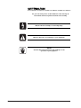
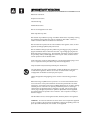
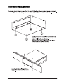
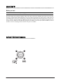
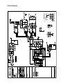
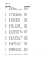
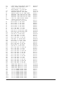
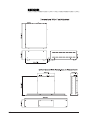
Soundcraft DPS-33 Power Supply
USER GUIDE
and
TECHNICAL MANUAL
1
IMPORTANT
Please read this manual carefully before
connecting your DPS-3 Power Supply
Unit to the mains for the first time.
© Harman International Industries Ltd. 2004
All rights reserved
Parts of the design of this product may be protected by worldwide patents.
Part
ZM0317-01
Part No.
No. ZM0317-02
Soundcraft is a trading division of Harman International Industries Ltd. Information in
this manual is subject to change without notice and does not represent a
commitment on the part of the vendor. Soundcraft shall not be liable for loss or damage whatsoever arising from the use of information or any error contained in this
manual.
No part of this manual may be reproduced, stored in a retrieval system, or
transmitted, in any form or by any means, electronic, electrical, mechanical,
optical, chemical, including photocopying and recording, for any purpose without the
express written permission of Soundcraft.
Harman International Industries Limited.
Cranborne House,
Cranborne Road,
Potters Bar,
Hertfordshire,
EN6 3JN
UK.
Tel: +44 (0) 1707 665000
Fax: +44 (0) 1707 660742
Email: [email protected]
www.soundcraft.com
2
Contents
Safety Symbol Guide ..............................................................................................................4
Important Safety Instructions ................................................................................................5
Fitting The Feet Or Rackmounting ..........................................................................................7
Connecting Up .......................................................................................................................8
Pin-outs Of DC Output Connector ...........................................................................................8
Circuit Diagram .....................................................................................................................9
PCB Layout ..........................................................................................................................10
Parts List ............................................................................................................................. 11
Dimensions ......................................................................................................................... 14
Warranty .............................................................................................................................. 15
3
SAFETY SYMBOL GUIDE
For your own safety and to avoid invalidation of the warranty all
text marked with these Symbols should be read carefully.
CAUTIONS
Must be followed carefully to avoid bodily injury.
WARNINGS
Must be observed to avoid damage to your equipment.
NOTES
Contains important information and useful tips on the
operation of your equipment.
4
IMPORTANT SAFETY INSTRUCTIONS
Read these instructions.
Keep these instructions.
Heed all warnings.
Follow all instructions.
Do not use this apparatus near water.
Clean only with a dry cloth.
Do not block any ventilation openings. Ventilation should not be impeded by covering
the ventilation openings with items such as newspapers, table cloths, curtains etc.
Install in accordance with the manufacturer's instructions.
Do not install near any heat sources such as radiators, heat registers, stoves, or other
apparatus (including amplifiers) that produce heat.
Do not defeat the safety purpose of a polarised or grounding type plug. A polarised
plug has two blades with one wider than the other. A grounding type plug has two
blades and a third grounding prong. The wide blade or the third prong are provided
for your safety. If the provided plug does not fit into your outlet, consult an electrician for replacement of the obsolete outlet
Protect the power cord from being walked on or pinched particularly at plugs, convenience receptacles and the point where they exit from the apparatus.
Only use attachments/accessories specified by the manufacturer.
Use only with the cart, stand, tripod, bracket or table specified by the manufacturer,
or sold with the apparatus. When a cart is used, use caution when moving the
cart/apparatus combination to avoid injury from tip-over.
Unplug this apparatus during lightning storms or when unused for long periods of
time.
Refer all servicing to qualified service personnel. It is recommended that all maintenance and service on the product should be carried out by Soundcraft or its authorised agents. Soundcraft cannot accept any liability whatsoever for any loss or damage
caused by service, maintenance or repair by unauthorised personnel. Servicing is
required when the apparatus has been damaged in any way, such as power-supply
cord or plug is damaged, liquid has been spilled or objects fallen into the apparatus,
the apparatus has been exposed to rain or moisture, does not operate normally, or
has been dropped.
No naked flame sources, such as lighted candles, should be placed on the apparatus.
WARNING: To reduce the risk of fire or electric shock, do not expose this apparatus
to rain or moisture. Do not expose the apparatus to dripping or splashing and do not
place objects filled with liquids, such as vases, on the apparatus.
5
THIS APPARATUS MUST BE EARTHED. Under no circumstances should the safety
earth be disconnected from the mains lead.
The mains supply disconnect device is the mains plug. It must remain accessible so as
to be readily operable when the apparatus is in use.
If any part of the mains cord set is damaged, the complete cord set should be
replaced. The following information is for reference only.
The wires in the mains lead are coloured in accordance with the following code:
Earth (Ground):
Green and Yellow (US - Green/Yellow)
Neutral:
Blue
(US - White)
Live (Hot):
Brown
(US - Black)
As the colours of the wires in the mains lead may not correspond with the coloured markings identifying the terminals in your plug, proceed as follows:
The wire which is coloured Green and Yellow must be connected to the terminal in the
plug which is marked with the letter E or by the earth symbol.
The wire which is coloured Blue must be connected to the terminal in the plug which is
marked with the letter N
The wire which is coloured Brown must be connected to the terminal in the plug which is
marked with the letter L
Ensure that these colour codes are followed carefully in the event of the plug being changed
This unit is capable of operating over a range of mains voltages as marked on the rear
panel. It is important to ensure that the correct mains fuse is fitted before switching
on the unit.
6
FITTING THE FEET OR RACKMOUNTING
7
CONNECTING UP
Before you start
Ensure the DPS-3 power supply is NOT connected to the Mains and is turned OFF.
The Power supply can be positioned anywhere within reach of the console and an available power socket, but is best rackmounted in a position where airflow through the vents is not obstructed and where the power switch or cables cannot be
accidentally knocked. Connect the multi-way power cable between the DPS-3 External Power Supply and the console’s connector. Screw the connector locking ring clockwise on both units to secure the cable. The locking ring should be firm, but
not tight. Connect an IEC type mains cable with the plug fused at 3 AMPS, to the mains input socket on the DPS-3. Connect
the other end to the nearest plug socket and switch on the power to the DPS-3.
PIN-OOUTS OF DC OUTPUT CONNECTOR
8
Circuit Diagram
9
PCB Layout
10
PARTS LIST
GB4 PSU ASSY
R0050A-04-AF
Ident
—
—
—
—
—
Part Number
S0050A-04
PN10004
PN1240
ZC0231
BR1
C1
C2
C3
C4
C5
C6
C7
C8
C9
C10
C11
C12
C13
C14
C15
C16
C17
C19
C20
C21
C22
C23
C24
C29
C30
C34
C37
C38
C40
C41
C44
C45
C46
C51
CN1
CN2
D1
D2
D3
D4
D5
D6
D7
D8
D10
Description
GB4 PCB PSU BOARD
HEATSINK THERMALOY 7121D XV05POWER STN MIXER PSU HEATSINK
DRIVER MOUNTING CLIP
(Safety Critical Part)!
FUSE 5X20MM T 2A 250V
BDG RECT KBU6K SIL 6A 800V
CAP ELEC VERT 1000UF 25V ESR 1
CAP ELEC VERT 1000UF 25V ESR 1
CAP ELEC VERT 1000UF 25V ESR 1
CAP ELEC VERT 1000UF 25V ESR 1
CAP ELEC VERT 1000UF 25V ESR 1
CAP CER 1NF 1KV 5MM PITCH
CAP CER 1NF 1KV 5MM PITCH
CAP CER 1NF 1KV 5MM PITCH
CAP ELEC VERT 100UF 100V
CAP CER 220PF 1KV DISC
CA-CP
CAP CER 220PF 1KV DISC
CA-CP
CAP CER ML 0.1UF 50V 5MM
CAP CER ML 0.1UF 50V 5MM
CAP CER ML 0.1UF 50V 5MM
CAP CER ML 0.1UF 50V 5MM
CAP ELEC VERT 47UF 63V SKP 0.2
CAP ELEC VERT 47UF 63V WGP ESR
MICRO-BOX 5MM 5% 100V 220N
CAP ELEC VERT 100UF 100V
CAP 100N 250V POLY DIP 10MM
CAP ELEC 10UF 100V VERT 105DEG
CAP ELEC 330UF 25V VERT 105DEG
(Safety Critical Part)!
CAP CER 4N7 250V Y1 RATED
MICRO-BOX 5MM 5% 63V 1N
CAP CER ML 1000PF 100V 5% 5MM
CAP ELEC RAD 560UF 400V 35X35
CAP ELEC VERT 1UF 63V SSP 4D 7
CAP CER ML 0.1UF 50V 5MM
CAP CER 150PF 100V TPD 0.2"
(Safety Critical Part)!
CAP 1UF 275VAC RFI CLASS X2
MICRO-BOX 5MM 5% 470NF 63/100V
CAP ELEC VERT 1UF 63V SSP 4D 7
MICRO-BOX 5MM 5% 63V 2N2
CAP CER ML 0.1UF 50V 5MM
(Safety Critical Part)!
IEC FILTER 3A PCB MTG.
20WY G80 VERT ML HDR LATCH
RECTIFIER MUR1640CT TO-220
RECTIFIER MUR1640CT TO-220
RECTIFIER MUR1640CT TO-220
DIODE RECTIFIER 8ETX06 600V 8A
DIODE FAST TYPE EGP10G 400V 1A
DIODE SF1600 1A FAST SOD-57
DIODE 1N5402 200V 3A PRFMD .6"
DIODE RECTIFIER 8ETX06 600V 8A
DIODE FAST TYPE EGP10G 400V 1A
ZD8002
BC0222
CE0512
CE0512
CE0512
CE0512
CE0512
CA0055
CA0055
CA0055
CE10046
CA10018
CA10018
CA0026
CA0026
CA0026
CA0026
CE0402
CE0466
CC0251
CE10046
CC10026
CE0535
CE0536
CC10088
CC0238
CA0015
CE10049
CE0485
CA0026
CA0045R
CX10000
CC0267
CE0485
CC0240
CA0026
FJ8046
FA0085
BC10003
BC10003
BC10003
BC0226
BA10014
BA10008
BA0009
BC0226
BA10014
11
D11
D14
F1
IC3
L1
L2
L4
L5
L6
L8
OPT1
R1
R2
R3
R4
R5
R6
R7
R8
R9
R10
R11
R12
R13
R14
R15
R22
R24
R28
R29
R30
R31
R32
R33
R34
R35
R36
R39
R40
R44
R46
R47
R48
R49
R52
R53
SP1
SP2
SP3
SP4
SP5
SP6
SP7
SP8
SP9
SP10
SP11
SP12
12
DIODE FAST TYPE EGP10G 400V 1A
TL431 SHUNT REGULATOR TO92
(Safety Critical Part)!
FUSE HOLDER 6.3A PCB MTG
VOLTAGE MODE PWM DIP-14
INDUCTOR-OUTPUT -GB4/RENO
FERRITE BEAD AX 5X3.5MM TAPED
INDUCTOR 10UH TOKO A823LY-100K
INDUCTOR 10UH TOKO A823LY-100K
INDUCTOR 10UH TOKO A823LY-100K
DIGI 328 LINE FILTER CHOKE
(Safety Critical Part)!
OPTO TRANSISTR H11AV1AVM
MF 1W RES 5% 4R7 PRO1
MF 1W RES 5% 4R7 PRO1
MF 1W RES 5% 4R7 PRO1
MF 1W RES 5% 4R7 PRO1
MF 1W RES 5% 4R7 PRO1
AP 0.25W RES 1% 1K BL
AP 0.25W RES 1% 1K BL
RES 22K 5% 5W WW TYP.SQM5
RES 22K 5% 5W WW TYP.SQM5
AP 0.25W RES 1% 1K BL
RES 4K7 5% 1W MF PRO1
AP 0.25W RES 1% 1K BL
AP 0.25W RES 1% 1K BL
MF 0.25W RES 1% 20K BL
RES 0R47 5% 2W MF PF02
RES 0R47 5% 2W MF PF02
MF 2W RES 5% 150K PRO2
MF 1W RES 5% 10R PRO1
MF 0.25W RES 1% 3K6 BL
MF 1W RES 5% 10R PRO1
RES 4K7 5% 1W MF PRO1
MF 0.25W RES 1% 680K BL
MF 0.25W RES 1% 1M BL
AP 0.25W RES 1% 1K BL
MF 0.25W RES 1% 470K BL
MF 0.25W RES 1% 10K BL
MF 0.25W RES 1% 22K BL
AP 0.25W RES 1% 1K BL
MF 0.25W RES 1% 12K BL
AP 0.25W RES 1% 1K BL
AP 0.25W RES 1% 1K BL
MF 0.25W RES 1% 6K8 BL
MF 0.25W RES 1% 220R BL
MF 0.25W RES 1% 1K1 BL
MF 0.25W RES 1% 10K BL
SPADE TAB VERT PC 0.125C
SPADE TAB VERT PC 0.125C
SPADE TAB VERT PC 0.125C
SPADE TAB VERT PC 0.125C
1/4" PC MNTNG BLADE VERT
1/4" PC MNTNG BLADE VERT
1/4" PC MNTNG BLADE VERT
1/4" PC MNTNG BLADE VERT
1/4" PC MNTNG BLADE VERT
1/4" PC MNTNG BLADE VERT
1/4" PC MNTNG BLADE VERT
1/4" PC MNTNG BLADE VERT
BA10014
BE0503
ZD8023
BE10032
P0009-01
HC0021
HC0028
HC0028
HC0028
HC0037
BD0396
AE0047
AE0047
AE0047
AE0047
AE0047
AP1349
AP1349
AG10015
AG10015
AP1349
AE10021
AP1349
AP1349
AP1380
AE10036
AE10036
AE2154
AE0100
AP1362
AE0100
AE10021
AP1417
AP1421
AP1349
AP1413
AP1373
AP1381
AP1349
AP1375
AP1349
AP1349
AP1369
AP1333
AP1350
AP1373
FF10022
FF10022
FF10022
FF10022
FF0676
FF0676
FF0676
FF0676
FF0676
FF0676
FF0676
FF0676
SP13
SP14
SP15
SP16
SW1
TX1
TH1
TR1
TR2
TR4
ZD1
ZD3
SPADE TAB VERT PC 0.125C
SPADE TAB VERT PC 0.125C
SPADE TAB VERT PC 0.125C
SPADE TAB VERT PC 0.125C
(Safety Critical Part)!
PANASONIC DPST HOR MAINS SWT
TRANSFORMER SMPS.GB4/RENO
(Safety Critical Part)!
THERMISTER 3A INRUSH LIMITER
TRANS TIP122 TO220
XE01MOSFET PWR.STP13NK60Z/FP
TRANS TIP122 TO220
XE01ZENER DIODE 1.3W 51V
ZENER DIODE 250MW 13V
FF10022
FF10022
FF10022
FF10022
DJ8002
P0008-01
AZ2279
BD10026
BD10051
BD10026
BB0131
BB10025
DPS3 LED PCB ASSY. AF R0105A-01-AF
Ident
LED1
R1
Description
LED 3MM ULTRA RED ROUND
SM0805 RES 2K4 1% 0.1W T200
Part Number
JA10025
AS0242R-0805F
DPS3 SRC PCB ASSY AF R0099A-02-AF
Ident
—
C1
C2
C3
C4
C5
C6
Description
PCB DPS3 SRC BOARD
CAP CER 100NF 10% 50V
CAP CER 100NF 10% 50V
CAP CER 100NF 10% 50V
CAP CER 100NF 10% 50V
CAP CER 100NF 10% 50V
CAP CER 15NF 10% 100V
X7R
X7R
X7R
X7R
X7R
Part Number
S0099-02
CS7104R-0805K
CS7104R-0805K
CS7104R-0805K
CS7104R-0805K
CS7104R-0805K
CS7153R-0805K1
13
DIMENSIONS
14
WARRANTY
1 Soundcraft is a trading division of Harman International Industries Ltd .
End User means the person who first puts the equipment into regular
operation.
Dealer means the person other than Soundcraft (if any) from whom the
End User purchased the Equipment, provided such a person is authorised
for this purpose by Soundcraft or its accredited Distributor.
Equipment means the equipment supplied with this manual.
2 If within the period of twelve months from the date of delivery of the
Equipment to the End User it shall prove defective by reason only of faulty
materials and/or workmanship to such an extent that the effectiveness
and/or usability thereof is materially affected the Equipment or the defective component should be returned to the Dealer or to Soundcraft and
subject to the following conditions the Dealer or Soundcraft will repair or
replace the defective components. Any components replaced will become
the property of Soundcraft.
3 Any Equipment or component returned will be at the risk of the End User
whilst in transit (both to and from the Dealer or Soundcraft) and postage
must be prepaid.
4 This warranty shall only be valid if:
a) the Equipment has been properly installed in accordance with instructions contained in Soundcraft’s manual; and
b) the End User has notified Soundcraft or the Dealer within 14 days of
the defect appearing; and
c) no persons other than authorised representatives of Soundcraft or the
Dealer have effected any replacement of parts maintenance adjustments or
repairs to the Equipment; and
d) the End User has used the Equipment only for such purposes as
Soundcraft recommends, with only such operating supplies as meet
Soundcraft’s specifications and otherwise in all respects in accordance
Soundcraft’s recommendations.
5 Defects arising as a result of the following are not covered by this
Warranty: faulty or negligent handling, chemical or electro-chemical or
electrical influences, accidental damage, Acts of God, neglect, deficiency in
electrical power, air-conditioning or humidity control.
6 The benefit of this Warranty may not be assigned by the End User.
7 End Users who are consumers should note their rights under this Warranty
are in addition to and do not affect any other rights to which they may be
entitled against the seller of the Equipment.
15
IMPORTANT
Please read this manual carefully before
connecting your DPS-3 Power Supply
Unit to the mains for the first time.
© Harman International Industries Ltd. 2004
All rights reserved
Parts of the design of this product may be protected by worldwide patents.
Part No. ZM0317-01
Soundcraft is a trading division of Harman International Industries Ltd. Information in
this manual is subject to change without notice and does not represent a
commitment on the part of the vendor. Soundcraft shall not be liable for loss or damage whatsoever arising from the use of information or any error contained in this
manual.
No part of this manual may be reproduced, stored in a retrieval system, or
transmitted, in any form or by any means, electronic, electrical, mechanical,
optical, chemical, including photocopying and recording, for any purpose without the
express written permission of Soundcraft.
Harman International Industries Limited.
Cranborne House,
Cranborne Road,
Potters Bar,
Hertfordshire,
EN6 3JN
UK.
Tel: +44 (0) 1707 665000
Fax: +44 (0) 1707 660742
Email: [email protected]
www.soundcraft.com
16