1
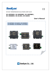
Release Version 1.0 Art. 38979 UTP Long Distance HD-SDI Transmitter SEE-SCUHC01S User's Guide Release Version 1.0 Precautions and Safety Guidelines Please read this user manual thoroughly prior to using this product. Do not install the product in places having extremely low or high temperature conditions, those exposed to rain, snow, or high humidity, places containing or exposed to oil and gas, or to vibration, shock, direct sunlight or to outdoor weather conditions. Places exposed to radio waves (RF) or near to power lines. They may cause low performance or a product malfunction. Do not disassemble the product or insert foreign objects. The unit may pose an electrical shock hazard. Make sure not to get an electric shock while using the device. Only use safety approved power supply units with electromagnetic compatibility. Do not use and/or connect any devices inappropriate to the unit. It may cause a product malfunction or fire. Use this product only in the temperature range -10°C to +50°C. Prior to turning on the device, check the condition of the data cable insulation connected to external devices. Before installing the product, or applying power, check its voltage rating. Do not subject the product to physical shocks. Do not use the device if smoke or a burning smell is being produced. It may cause a fire. If any smoke or a burning smell is produced, immediately turn the unit off and remove the power cable. Contact your distributor and get the product checked. If the power does not turn ON, make sure the power cable is correctly connected. Only UTP (STP) cable should be used for the signal transmission. Transmission distance may vary depending on the type of the cable Check specifications and installation guideline before using the product Contact A/S center for inquiries Due to various external noises and electrical interference, it is recommendable to use the STP (Shielded Twist Pair) Cable. Release Version 1.0 1. Introduction 1-1. Overview SEE-SCUHC01S is a long distance transmission device over UTP cable which consists of transmitter and receiver. The device also supplies power to the camera and transmits RS-485 data from controller to control PTZ functions of the camera. It is very cost-effective and economical solution as it enables long distance HD-SDI signals transmission over UTP cable up to 120 meter without replacing existing cables and expenditures for constriction work for installing repeaters in the middle which are essential in case of transmitting signals over long distance. 1-2. Features • HD-SDI signals transmission up to 120m over CAT. 5e / CAT.6 • Transmitter can be powered by receives power over UTP cable • Support RS-485 Data communication interface • Possibility to use existing UTP cable to install HD-SDI devices 1-3. HD Signal Standards (Inputted signal to Transmitter / Outputted signal from Receiver only) • SEE-SCUHC01S conforms to the SDI signal standards of the SMPTE (Society of Motion Picture and Television Engineers). •The SDI (Serial Digital Interface) is an innovative transmission system which can transmit uncompressed video signals over a single cable. As SDI signals are digital, it is possible to transmit signals over limitless distances without modification thanks to equalizing and re-clocking feature at certain distance. Also, there is no aging or delay caused by compression. HD-SDI (SMPTE 292M) 3G-SDI (SMPTE 424M) 1280 x 720p, 24/ 25/ 30/ 50/ 60 Hz 1920 x 1080i, 50/60 Hz 1920 x 1080p, 24/25/30 Hz Not supported Release Version 1.0 2. Components SEE-SCUHT01S (Transmitter) Model DC Cable SEE-SCUHR01S (Receiver) Manual SEESCUHC01S 3. Product Parts and Peripheral Device Connection - Product Parts and Function SEE-SCUHT01S(Tx.) ① ④ ② 1 AC/DC Input: Power input port (Please check the polarity in case of DC power) 2 HD-SDI Input: HD-SDI signal input port for connecting coaxial cable. 3 RS-485 DATA Output: RS-485 control data output port for connecting HDSDI Camera (Please check the polarity) 4 RJ-45 Connector (568-B Type) No. 1 2 3 4 Feature SDI Signal + Output SDI Signal - Output RS-485 + Input AC/DC + Through No. 5 6 7 8 Feature AC/DC + Through RS-485 – Input AC/DC – Through AC/DC – Through LED Indication LED Color LED Status Description Yellow On Power input Green On HD-SDI Signal input Release Version 1.0 SEE-SCUHR01S(Rx.) ① ④ ② 1 RJ-45 Connector (568-B Type) No. 1 2 3 4 Feature SDI Signal + Input SDI Signal - Input RS-485 + Output AC/DC + Through No. 5 6 7 8 Feature AC/DC + Through RS-485 - Output AC/DC - Through AC/DC - Through LED Indication LED Color LED Status Description Yellow On Power input Green On HD-SDI Signal input 2 RS-485 DATA Input: RS-485 control data input port for connecting with controller (Please check the polarity) 3 HD-SDI Output: HD-SDI output port for connecting HD-SDI DVR with Coaxial cable 4 AC/DC Input: AC/DC Power input port (Please check the polarity in case of DC power) ※ Caution. Please do not input the power both Transmitter and Receiver simultaneously (please refer to “4. Connection diagram” ) Release Version 1.0 4. Connection Diagram # Installation Guide Depending on cable type and connector, HD-SDI signals transmission distance may vary and the specified transmission distance cannot be guaranteed in case of using poor quality cables → Make sure that cable run does not exceed the specified transmission distance range → Use BNC connector with low loop resistance (75Ω BNC connector) → When the cable is being extended or terminated it should be connected in the following way: BNC-M BNC-JJ connector BNC-M # The end of the coaxial cable must be connected with BNC-M as shown in the figure. DO NOT use RCA cable and connector with this product # Due to various external noise and electrical interference we suggest using STP (Shielded Twist Pair) CABLE type Release Version 1.0 5. Signals transmission depending on cable type - UTP and Coaxial cable distance Attenuation (dB/100m) Cable Max . distance transmission (unit: m) 1.5 G / HD-SDI 제조사 From transmitter top receiver 1.5 G From camera to transmitter From Receiver to DVR U-JIN 17.8 30 30 KUMKANG 17.8 30 30 L-5CFB CANARE 20.3 25 25 L-5C-2V CANARE 25.7 20 L-3C-2V CANARE 40 15 S-5C-FB TACHII 18.7 30 S-5C-FV TACHII 19.7 25 25 RG6/U(1694A) BELDEN 16.5 30 30 RG59/U(1505A) BELDEN 21.4 20 20 5C-HFBT • • • • UTP Cable CAT.5e / CAT.6 Max. 120m 20 15 30 The max. transmission distance between devices is always the same. Depending on the environment conditions, it is recommended to use 90% of the allowed cable run stated above. Use BNC connectors with a low connection resistance. Avoid using excessive force when installing coaxial cable and BNC connection # Due to various external noise and electrical interference we suggest using STP (Shielded Twist Pair) CABLE type Release Version 1.0 6. SPECIFICATION MODEL Video in/out Bandwidth Power consumption Power input Max. transmission distance SDI In/Out SIGNAL In/Out Connection Ports Power Input RS-485 In/Out YELLOW LED GREEN Temperature/ Humidity Case/Weight Dimensions, mm SEE-SCUHT01S SEE-SCUHR01S HD-SDI 1.485Gbps Under 3W Under 3W DC 12V / 1A , AC 24V / 0.5A UTP Cable (CAT.5e / CAT.6) Max. 120m BNC_F(75Ω) RJ-45(T568B Type) Terminal Block(2P) Terminal Block(2P) ON: Power input ON: Signal Input -10℃ ~ +50℃ / 0 ~ 80% Aluminum/ 50g Aluminum/ 50g 55(W) X 33(H) X 20.5(D)mm 7. FAQ 7-1. Power is not supplied to the transmitter 1) Please check the Yellow LED Status of the Transmitter and if it is off, please check the connection of the transmitter and the receiver. → Make sure the Tx. and Rx. are connected properly. 2) Please check the UTP cable has been connected properly. → Make sure the cable junction point, cable short. 7-2. LED is On but Video image is not outputted. 1) Please make sure that the UTP cable run doesn’t exceed the recommended transmission distance. 2) The max. distance of the coaxial cable will depend on the cable quality, please note that if the coax cable run doesn’t exceed the recommended transmission distance. 3) Please check the image resolution (Full HD 1920*1080P 60/59.94/50Hz image cannot be transmitted with the device) 4) Make sure that the cable has been connected properly. → For cable connection or extension, please refer to the picture shown as below; BNC-M - BNC-JJ - BNC-M ; # The end of the coaxial cable must be connected with BNC-M as shown in the figure. DO NOT use RCA cable and connector with this product. Release Version 1.0 Warranty Certificate Model No. Serial No. Distributor Date you purchased Place you purchased Warranty Period Name Purchaser Address One (2) year from the date of purchase This product has passed thorough quality control and test, and if this gets broken during normal use, we provide 24 months warranty service. Contact your distributor after checking out any defect in the products. Warranty covers only those defects that arise as a result of normal use of the product and repair service free of any charge will be provided according to the warranty certificate. We charge you with the fee for parts and services provided despite of free warranty service period in case of : Breakage or trouble made by natural disaster. Breakage or trouble made by breaking the product guide or manual. Breakage or trouble made by wrong power voltage or frequency. When you want to reassemble for full system or replace parts within warranty service period. When unauthorized person modified or made damage on the product trying to repair it. -