1
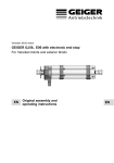
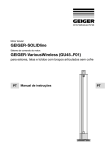
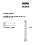
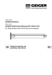
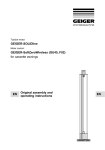
Tubular motor: GEIGER-SOLIDline Motor control: GEIGER-Easy (GU45..E01) for rolling shutters, screens and folding arms awnings DE Original-Montage- und Betriebsanleitung EN Original assembly and operating instructions FR Notice originale de montage et d’utilisation ES Instrucciones originales de instalación y funcionamiento IT Istruzioni originali di installazione e funzionamento www.geiger.de EN EN 1 Index 1. General information...................................................................2 2.Guarantee...................................................................................2 3. Intended use...............................................................................3 4. Safety instructions.....................................................................3 5. Safety instructions for assembly.............................................4 6. Installation instructions............................................................5 7. Information for the specialist electrician.................................6 8. Connection of the setting switch.............................................6 9. Obstacle detection...................................................................10 10. End position correction...........................................................10 11. What to do if…..........................................................................10 12.Maintenance.............................................................................10 13. Declaration of conformity....................................................... 11 14. Technical data..........................................................................12 15. Notes on waste disposal.........................................................12 EN 1. General information Dear customer, By purchasing a GEIGER motor you have decided on a quality product from GEIGER. Thank you very much for your decision and the confidence placed in us. Before you put this drive into operation please observe the following safety instructions. It serves for the prevention of danger and for the avoidance of personal injury and damage to property. The installation and operating instructions contain important information for the installer, the specialist electrician and the user. Please pass on these instructions if you transfer the product. These instructions should be kept by the user. 2. Guarantee In the case of incorrect installation contrary to the installation and operating instructions and/ or constructional modification, the legal and contractual guarantee for property damage and product liability lapses. 2 EN Gerhard Geiger GmbH & Co. KG | 100W0518 en V001 0315 3. Intended use The tubular motors of the model range SOLIDline (GU45..E01) with electronic limit stop are designed exclusively for the operation of rolling shutters, folding arms awnings and screens. The motors may not be used for the operation of roller grilles, garage doors, furniture and lifting tools. GU 45 xx x Motor control Torque in Nm Motor diameter GEIGER universal drive 4. Safety instructions Important safety instructions. For personal safety, it is important to follow these instructions. Please keep these II ATTENTION: instructions for future reference. ff Do not allow children to play with stationary controls. Keep remote controls away from children. ff The installation is to be checked regularly for defective balance, signs of wear or damaged cables and springs, if relevant. ff Do observe the moving sun protection system and keep persons away until it has closed completely. ff When operating the manual release with the sun protection system open, please be cautious as it can fall down quickly if springs or tapes wear off or are broken. ff Do not operate the device if operations such as, for example, window cleaning are to be carried out in the vicinity. ff Disconnect the automatic controlled device from the mains power supply if operations such as, for example, window cleaning are being carried out in the vicinity. ff During operation observe the danger zone. ff Do not use the installation if people or objects are in the danger zone. ff Urgently shut down damaged installations until repair. ff Unconditionally shut down the unit during maintenance and cleaning operations. ff Pinching and shearing points are to be avoided and must be secured. ff This appliance can be used by children aged 8 and above and persons whose physical, sensorial or mental capacities are impaired, or who have no experience or know-how if they have been supervised or been given instructions on the use of the appliance and if they understand the possible resulting dangers. Children are not permitted to play with the device. Cleaning and maintenance should not be carried out by children. ff The rated sound pressure level is less than 70 dB(A). ff Disconnect the device from the mains power supply for maintenance and replacement of parts. If the motor is disconnected via a plug connection the operator must be able to control - from any place to which it has access – that the plug is removed. If this is not possible - due to design or installation - the disconnection from the power supply must be ensured via locking in the disconnected position (e.g. isolator). ff The motor tube can get very hot during prolonged use. When working on the unit, do not touch the tube before it has cooled down. www.geiger.de EN 3 EN 5. Safety instructions for assembly Important safety instructions. Follow all installation instructions, as incorrect installation can lead to serious injuries. II ATTENTION: ff When mounting the motor without any mechanical protection of the driven parts and of the tube which may become hot, the motor must be installed at a height of at least 2.5 m above the ground or of another level which provides access to the drive. ff Before the motor is installed, all cables which are not needed are to be removed and all equipment which is not needed for power-operated actuation is to be put out of operation. ff The actuating element of a manual release must be mounted at a height of less than 1.8 m. ff If the motor is controlled by a switch or pushbutton, the switch or pushbutton must be mounted within eyeshot of the motor. The switch or pushbutton must not be located in the vicinity of moving parts. The height of installation must be at least 1.5 m above the floor. ff Permanently installed control devices must be attached visibly. ff In case of devices extending horizontally, a horizontal distance of at least 0.4 m must be respected between the fully extended part and any other fixed element. ff The rated speed and the rated torque of the motor must be compatible with the device. ff The mounting accessories that are used must be designed in accordance with the selected rated torque. ff Good technical knowledge and good mechanical skills are necessary for the motor installation. Incorrect installation can lead to serious injury. Electrical work must be carried out by a qualified electrician in accordance with the regulations in force locally. ff Only use connecting cables that are suitable with the environmental conditions and which meet the construction requirements. (see accessories catalogue) ff If the device is not equipped with a connecting cable and a plug, or other means for disconnecting from the mains with a contact opening on each pole according to the conditions of the overvoltage category III for full disconnection, a disconnecting device of this type must be incorporated into the permanently installed electrical installation according to the wiring rules. ff Do not mount the connecting cables near hot surfaces. ff A plug for the disconnection of the motor from the power supply must be accessible after installation. ff Damaged connecting cables must be replaced by GEIGER connecting cables of the same type. ff The device must be mounted as described in the installation instructions. Fixations shall not be made with adhesives since they are regarded as unreliable. EN 4 EN Gerhard Geiger GmbH & Co. KG | 100W0518 en V001 0315 6. Installation instructions fixing, the strength of the masonry or of the subsurface is to be checked. II Before to installation please check to ensure there is no visible damage to the motor like cracks or open cables. II Prior If the tube is screwed/riveted to the drive, the measure must be taken from the tube end to the center of the drive and marked on II Caution: the tube. When drilling the winding shaft never drill into the area of the tubular motor! When inserting into the shaft, the tubular motor must not be struck and must not be allowed to fall into the shaft. Installation into the rolling shutter: Fix motor support to available stud bolts or in the side frame. Insert motor into the shaft with a suitable adapter and drive up to the stop of the shaft adapter. Insert roller capsule on the opposite side. Put shaft with motor on motor support or on pivoting engine bearer. On the opposite side pull out roller capsule until bolt fits into ball bearing. Screw together roller capsule with shaft. Screw together shaft with tubular carrier. Fix rolling shutter casing to shaft. Alternative: use fixation plates for front-mounted shutters in order to fix the motor. The bearer locks into place. For removal, turn spring ring. Installation into awnings and screens: Insert motor with a suitable adapter and drive into the shaft up to the stop of the shaft adapter. Fix the motor support on the awning. Fix the motor together with the shaft on the motor support. The bearer locks into place. EN Depending on the selected motor head, different fixation systems can be used: –– Place the motor with square insert in the star-shaped bearer and lock with pin –– Place the motor into the existing engine bearer and lock –– Place the motor in a compatible engine bearer with clip system and lock with spring or rotating lever GEIGER SOLIDline motor is suitable for shaft diameters from 50 mm! II The www.geiger.de EN 5 7. Information for the specialist electrician Important installation instructions. Please follow all instructions since HH Caution: incorrect installation can lead to Mains: 230V / 50Hz L1 the destruction of the motor and the switching unit. N PE blue 1 2 3 black N brown PE green/yellow The operations with the service clamps may be accomplished only by an electrical specialist. Motors with electronic limit stops can be connected in parallel. In this case the maximum load of the switching unit must not be exceeded. When changing the running direction the switchover must be effected through an off-position. When changing the running direction the switchover time must be at least 0.5 s. With a three-phase network, please use the same external conductor in order to control the UP and DOWN directions. PVC cables are not suitable for equipment used outdoors or exposed to prolonged high levels of UV radiation. These cables should not be used if they are likely to touch metal parts that can heat up to temperatures exceeding 70°C. Connecting cables with plug connectors of the Hirschmann Company are tested and approved with couplings of the Hirschmann Company. In order to prevent a malfunction caused by coupling, the supply line (ref. NYM) from the actuator/switch to the motor must not exceed 100m in case of motors with electronic end stops. Electronic / mechanical limit stop 8. Connection of the setting switch order to set the end positions on SOLIDline motors, any setting can be used that has a programming key or that allows a II Inswitch simultaneous UP/DOWN command. In this case, the UP/DOWN keys EN must be activated simultaneously instead of the programming key. Mains: 230 V~/50 Hz LED Direction keys Programming key PROG 1 2 Setting cable M56... Service terminals Connecting cable to limit stop Connect setting cable to the connecting cable of the motor (see diagram on the back of the setting switch). The assignment to the direction of rotation is dependent on the installation situation of the drive. Then connect the setting switch to the 230V mains. Article Number / GEIGER setting switch 6 M56F152 with service terminal (D), 5 wires, SMI compatible M56F153 with service terminal (CH), 5 wires, SMI compatible M56F154 with service terminal (D), 4 wires EN Gerhard Geiger GmbH & Co. KG | 100W0518 en V001 0315 The following installation types are possible: A Upper and lower end positions with stop B Upper end position freely adjustable / lower end position with stop C Upper end position with stop / Lower end position freely adjustable D Upper and lower end positions freely adjustable Rolling shutter is equipped with: End bar with stopper/ with anti-lift device End bar with stopper/ with anti-lift device Awning is equipped with: – End bar with stopper/ without anti-lift device awning arms used as stops End bar without stopper/ without anti-lift device no stops are used – Change/delete the end positions In order to change or delete the end positions, a new programming must be started (see «Setting of the end stops»). Programming the end positions / Rolling shutters Variant A: upper and lower end positions with stop Press programming key or UP and DOWN keys at the same time until the motor confirms (1 x click-click). Upper end position: Press the UP or DOWN key until the sun protection system has reached the upper stop and the motor switches off automatically. The upper end position is now stored. Lower end position: Press the UP or DOWN key until the sun protection system has reached the lower stop and the motor switches off automatically. EN The lower end position is now stored. The programming is completed and the motor returns to normal mode. Variant B: upper end position freely adjustable / lower end position with stop Press programming key or UP and DOWN keys at the same time until the motor confirms (1 x click-click). Upper end position: Press the UP or DOWN key until the sun protection system has reached the selected upper end position. Corrections with the UP and DOWN keys are possible. Press programming key or UP and DOWN keys at the same time until the motor confirms (2 x click-click). 2 x clickclick The upper end position is now stored. www.geiger.de EN 7 Lower end position: Press the UP or DOWN key until the sun protection system has reached the lower stop and the motor switches off automatically. The lower end position is now stored. The programming is completed and the motor returns to normal mode. Variant C: upper end position with stop / Lower end position freely adjustable Press programming key or UP and DOWN keys at the same time until the motor confirms (1 x click-click). Upper end position: Press the UP or DOWN key until the sun protection system has reached the upper stop and the motor switches off automatically. The upper end position is now stored. Lower end position: Press the UP or DOWN key until the sun protection system has reached the selected lower end position. Corrections with the UP and DOWN keys are possible. Press programming key or UP and DOWN keys at the same time until the motor confirms (3 x click-click). 3 x clickclick The lower end position is now stored. The programming is completed and the motor returns to normal mode. Variant D: upper and lower end positions freely adjustable Press programming key or UP and DOWN keys at the same time until the motor confirms (1 x click-click). EN Upper end position: Press the UP or DOWN key until the sun protection system has reached the selected upper end position. Corrections with the UP and DOWN keys are possible. Press programming key or UP and DOWN keys at the same time until the motor confirms (2 x click-click). 2 x clickclick 3 x clickclick The upper end position is now stored. Lower end position: Press the UP or DOWN key until the sun protection system has reached the selected lower end position. Corrections with the UP and DOWN keys are possible. Press programming key or UP and DOWN keys at the same time until the motor confirms (3 x click-click). The lower end position is now stored. The programming is completed and the motor returns to normal mode. 8 EN Gerhard Geiger GmbH & Co. KG | 100W0518 en V001 0315 Programming the end positions / open style folding arm awnings Variant C: upper end position with stop / Lower end position freely adjustable Press programming key or UP and DOWN keys at the same time until the motor confirms (1 x click-click). Upper end position: Press the UP or DOWN key until the sun protection system has reached the upper stop and the motor switches off automatically. The upper end position is now stored. Lower end position: Press the UP or DOWN key until the sun protection system has reached the selected lower end position. Corrections with the UP and DOWN keys are possible. Press programming key or UP and DOWN keys at the same time until the motor confirms (3 x click-click). 3 x clickclick The lower end position is now stored. The programming is completed and the motor returns to normal mode. Variant D: upper and lower end positions freely adjustable Press programming key or UP and DOWN keys at the same time until the motor confirms (1 x click-click). Upper end position: Press the UP or DOWN key until the sun protection system has reached the selected upper end position. Corrections with the UP and DOWN keys are possible. Press programming key or UP and DOWN keys at the same time until the motor confirms (2 x click-click). 2 x clickclick 3 x clickclick The upper end position is now stored. Lower end position: Press the UP or DOWN key until the sun protection system has reached the selected lower end position. Corrections with the UP and DOWN keys are possible. Press programming key or UP and DOWN keys at the same time until the motor confirms (3 x click-click). EN The lower end position is now stored. The programming is completed and the motor returns to normal mode. www.geiger.de EN 9 9. Obstacle detection When, after the teaching of the first complete, uninterrupted travel from one end position to the other end position is carried out, the torque needed is learnt. In any following complete, uninterrupted travel from end position to end position, the torque needed is automatically readjusted. Slow changes in the installation due to ageing, soiling, cold or heat are thus automatically taken into consideration. This process takes place for both running directions independently of one another. If a travel movement in up direction is blocked by an obstacle, the motor switches off. The running direction in which the obstacle was recognized is blocked. The block is removed if the motor has been operated in the opposite direction for a certain time. An obstacle must thus first be released before the motor can be operated again in the direction of the obstacle. 10.End position correction If the upper end position with stop (Variant A or C) is taught, the motor in future stops before reaching the stop in order to avoid a mechanical loading of the hangings. Checking of the end position, and if appropriate an end position correction, takes place after 5, 20, and then every 50 cycles. Should a hangings elongation have resulted, due to temperature changes, this is corrected at the next end position correction. If, due to temperature changes, modified winding behaviour should arise and the hangings should run against the stop, an immediate end position correction takes place. In addition, the counter for the end position correction is started afresh. 11.What to do if… Problem Motor does not run. EN Instead of in the upwards direction, motor runs downwards. Motor only runs in one direction. After running several times, the motor breaks down and no longer responds. Solution • Motor not plugged in. Please check the plug connection. • Check connecting cable for possible damage. • Check the mains voltage and allow the cause of the voltage breakdown to be tested by a specialist electrician. • The control leads are interchanged. Exchange black/brown control leads. • Motor in the end position. Run motor in the opposite direction. Re-adjust the end positions, if necessary. • The motor became too hot and has switched off. Try it again after a cooling time of about 15 min. 12.Maintenance The drive is maintenance-free. 10 EN Gerhard Geiger GmbH & Co. KG | 100W0518 en V001 0315 13.Declaration of conformity EC Declaration of Conformity Gerhard Geiger GmbH & Co. KG Antriebstechnik Schleifmühle 6 D-74321 Bietigheim-Bissingen Product: Venetian blind motor, motor for rolling shutter, motor for awnings Type designation: GJ56.. GR45.. GU45.. The designated product is in conformity with the European Directive: 2006/42/ EC “Directive 2006/42/EC of the European Parliament and of the Council of 17 May 2006 for the approximation of laws, regulations and administrative provisions of the Member States concerning machinery”. 2004/108/ EC “Directive 2004/108/EC of the European Parliament and of the Council of 15 December 2004 on the approximation of the laws of the Member States relating to electromagnetic compatibility and repealing Directive 89/336/EEC” The conformity of the designated product with the provisions of the directives is proved in particular by full compliance with the following standards: DIN EN 60335-1 DIN EN 60335-2-97 DIN EN 62233 DIN EN 55014-1 DIN EN 55014-2 DIN EN 61000-3-2 DIN EN 61000-3-3 EN301 489-03 EN300 220-3 EN The accredited VDE Testing and Certification Institute (EU Identification No. 0366) Merianstr. 28, D-63069 Offenbach, tests and certifies for the company Gerhard Geiger GmbH & Co. KG. Authorised representative for technical data: Gerhard Geiger GmbH & Co. KG Address: Schleifmühle 6, D-74321 Bietigheim-Bissingen Bietigheim-Bissingen, 15.02.2013 www.geiger.de Hans-Michael Dangel (General Manager) EN 11 14.Technical data Technical data of tubular motor SOLIDline-KS (GU45..) GU4510 GU4520 GU4530 GU4540 GU4550 Voltage 230 V~/50 Hz Current 0,47 A 0,63 A 0,8 A 1,0 A 1,0 A Cos Phi (cosj) >0,95 Inrush current (factor) x 1,2 Power 105 W 140 W 180 W 220 W 220 W Torque 10 Nm 20 Nm 30 Nm 40 Nm 50 Nm Speed 16 rpm 16 rpm 16 rpm 16 rpm 12 rpm Protection class IP 44 516,5 mm 546,5 mm 566,5 mm 586,5 mm 586,5 mm Total length1) Operating mode S2 4 min S2 5 min S2 4 min S2 4 min S2 4 min 39 dB(A) 41 dB(A) 41 dB(A) 43 dB(A) Sound pressure level2) Diameter 45 mm Weight approx approx approx approx approx 1,90 kg 2,20 kg 2,40 kg 2,70 kg 2,70 kg Ambient temperature / Operation:T = -10°C .. +60°C / H max. 90% humidity Storage : T = -15°C .. +70°C / dry and non-condensing place 1) SOLIDline-ZN: -1 mm / SOLIDline-COM + 3,5 mm / SOLIDline-SOC: + 3 mm 2) The average sound pressure level data are intended for guidance only. The values were determined by GEIGER at a distance of 1 m, with a hanging motor at idle speed and averaged over 10 seconds. There is no reference to any specific test standard. V DE Subject to technical modifications geprüfte Sicherheit 15.Notes on waste disposal Recycling of packaging materials In the interest of environmental protection, please contact your local government’s recycling or solid waste management department to learn more about the services it provides. EN Waste disposal of electric and electronic equipment Electrical and electronic equipment must be collected and disposed of separately in accordance with EU regulations. For technical questions, please call our service team at: +49 (0) 7142 938-333. They will be happy to assist you. Gerhard Geiger GmbH & Co. KG Schleifmühle 6 D-74321 Bietigheim-Bissingen Telephone: +49 (0) 7142 938-0 Telefax: +49 (0) 7142 938-230 E-Mail: [email protected] Internet: www.geiger.de 12 EN Gerhard Geiger GmbH & Co. KG | 100W0518 en V001 0315