1
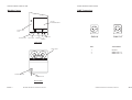
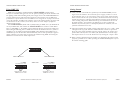
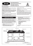
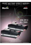
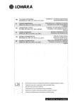
USER GUIDE
VERSION 1.3
MANUFACTURED BY
MARTIN MANUFACTURING (UK) PLC
BELVOIR WAY,
FAIRFIELD INDUSTRIAL ESTATE,
LOUTH, LINCOLNSHIRE. LN11 0LQ.
TEL:(01507) 604399
FAX:(01507) 601956
JEM
STAGE-HAZER DMX
STAGE-HAZER
DMX
MARTIN MANUFACTURING (UK) PLC
STAGE-HAZER USER GUIDE
STAGE-HAZER USER GUIDE
Fluids Suitable For This Machine:
How To Contact Us
Address:
Pro-Haze
Martin Manufacturing (uk) Plc
Belvoir Way,
Fairfield Industrial Estate,
Louth, Lincolnshire. LN11 0LQ.
Telephone:
+44 (0) 1507 604399
Fax:
+44 (0) 1507 601956
Email:
[email protected]
Website:
Http://www.jemsmoke.com/
Note:
The JEM warranty will be void if any fluid other then JEM approved fluid is used. If
other fluids are used there could be serious damage to the machine and the fluid
may not have been tested for use in public areas.
MARTIN MANUFACTURING (UK) PLC
MARTIN MANUFACTURING (UK) PLC
STAGE-HAZER USER GUIDE
STAGE-HAZER USER GUIDE
Notes
User Guide Index
•
•
•
•
•
•
•
•
Introduction
Safety
Machine Layout
Getting Started
Using The Remote Control
Using DMX 512
Trouble Shooting
How To Contact Us
Note:
Martin Manufacturing (UK) reserves the right to modify or change the
specification of this product without prior notice.
No part of this publication shall be copied without permission
© Martin Manufacturing (UK). 1999
PAGE 12
MARTIN MANUFACTURING (UK) PLC
MARTIN MANUFACTURING (UK) PLC
PAGE 1
STAGE-HAZER USER GUIDE
STAGE-HAZER USER GUIDE
Introduction
Notes
The STAGE-HAZER is a brand new machine from JEM which has been
designed to produce a perfect translucent environment for today’s intelligent
lighting effects.
Furthermore, this unique design is guaranteed to give the user maximum
reliability thanks to features such as the “Low fluid cut off system”,which
protects the pump in the event of running the machine dry.
Creating the perfect ambient haze relies heavily on the correct particle size
and dispersion. The STAGE-HAZER produces this by vapourising the special
working fluid at very precise temperature in a high mass heater block which
contains a cuperous helicoil of 3 metres length.
The product of this process is injected into the uniquely designed JEM
“Dispersal Chamber” where it is mixed with a turbulent airflow and projected
from the machine as an optically translucent haze at 1200 ft / minute (exit
velocity).
JEM has also used the “DTP” safety device, as used on the ZR12, ZR22 and
Techno-Fog to ensure the best possible overheat protection.
Features:
•
•
•
•
•
•
•
•
PAGE 2
DMX 512
“DTP” Safety system
SMD electronics
Low fluid cut off system
Variable output remote
9.5 Litre fluid capacity
Dispersal chamber
2 x High power Fan
MARTIN MANUFACTURING (UK) PLC
MARTIN MANUFACTURING (UK) PLC
PAGE 11
Safety
Check fluid level LED.
Replenish fluid container.
Contact your Distributor.
•
•
•
•
•
Low fluid level.
No fluid in container.
•
Thermocouple fault
Thermal trip fault
Always use a JEM approved fluid, other fluids could be dangerous and could
cause damage to the machine.
Always check the voltage is correct for use with the machine, the voltage
setting is printed on the serial label.
Always read the user guide before operating the machine, smoke machines
need to be operated carefully to avoid risk.
Do not remove the cover or attempt to repair a faulty machine, an authorized
JEM dealer should be contacted in the event of a faulty machine.
Always use smoke machines in well ventilated areas, over use could affect
sufferers of asthma or other chest conditions.
Do not use the machine if there is a faulty mains lead or plug this could be
dangerous.
Do not spill fluid over the machine, if fluid is spilt clean with clean water and
contact an approved JEM dealer for advice.
Mains Lead Wiring Instructions
No haze output.
Fuse on main PCB blown.
Remote control not connected.
The power LED does not light on
the remote control.
•
The ready LED does not light.
even after 15 minutes.
Main fuse blown..
No power connected.
The mains switch does not light
when I switch on.
CAUSE
SYMPTOM
PAGE 10
Check fuse on Main PCB.
Check connection of remote control.
Trouble Shooting
Check main fuse.
Check power is connected.
STAGE-HAZER USER GUIDE
CURE
STAGE-HAZER USER GUIDE
MARTIN MANUFACTURING (UK) PLC
Brown = Live
Blue = Neutral
Green/Yelllow = Earth
Note! This Appliance must be earthed
MARTIN MANUFACTURING (UK) PLC
PAGE 3
STAGE-HAZER USER GUIDE
STAGE-HAZER USER GUIDE
Machine Layout
DMX Connections
FLUID
COMPARTMENT
FLUID OUT
LED
READY LED
HEAT LED
1 2
2 1
3
3
DMX IN
DMX OUT
REMOTE
DMX IN
DMX OUT
TOP VIEW
TWIN FANS
PIN
1
2
3
FUNCTION
Ground
DMX Data -ve
DMX Data +ve
MAINS SWITCH
POWER LEAD
REAR VIEW
PAGE 4
MARTIN MANUFACTURING (UK) PLC
MARTIN MANUFACTURING (UK) PLC
PAGE 9
STAGE-HAZER USER GUIDE
STAGE-HAZER USER GUIDE
Using DMX 512
Getting Started
DMX 512 is an industry standard and the STAGE-HAZER is fitted with an
interface as standard. This gives the user the option of linking the smoke machines into
the lighting chain and controlling them from a single source. The STAGE-HAZER uses
a single channel to fire and control the output level, the interface can be addressed
from channel 1 up to channel 512. The address is set using the 10 way dip switch at the
rear of the machine. To address the channel, convert the channel number to binary and
set this number on the switches (on is down). There are some samples of different
channel settings below.
The STAGE-HAZER is fitted with two XLR sockets for DMX, one is for DMX IN &
one is for DMX OUT; this enables the STAGE-HAZER to be used in a chain. When
there is valid DMX, i.e. the XLR is connected and the desk is powered, the small green
LED will light indicating there is DMX connected to the machine. However, if there is
no address set, the LED will not light and DMX will be disabled. If an address is set
and DMX is present the machine will automatically start to heat up and after approximately 8 minutes you will be able to operate the machine using DMX. Increasing the
DMX level will increase the smoke output level.
•
•
•
Once you have selected the best position for the STAGE-HAZER you can
begin to use the machine. First check the power supply you have is correct
for the machine .If it is, you can connect to the power supply and switch the
mains switch on at the rear of the machine; the machine will start to heat up
and the fan will run. It will take approximately 8 minutes for the machine to
reach working temperature. While it heats up you should check the level in
the fluid container; the container can hold up to 9.5 litres of fluid. The
machine may not heat if there is inadequate fluid in the container (the red
‘fluid out’ LED must not be on).
When the machine has reached working temperature the green “ready” LED
will light on the top of the machine and the machine can now be operated.
Press the prime button until haze appears from the output; the pump is now
primed. This will only have to be done if the fluid lines have become empty.
The output can now be set to the desired level by turning the “output” knob.
When you have finished using the machine you should turn the mains switch
off. If any problems occur when operating the STAGE-HAZER please refer to
the trouble shooting guide.
1 2 3 4 5 6 7 8 9 10
ON
16
32
64
128
256
512
1248
DMX Value
1 2 3 4 5 6 7 8 9 10
PAGE 8
1248
16
32
64
128
256
512
Valid DMX LED
Address Switches
1 2 3 4 5 6 7 8 9 10
ON
ON
Switches 3,7, &9 on
Address set to 324
Switches 1 & 5 on
Address set to 17
MARTIN MANUFACTURING (UK) PLC
MARTIN MANUFACTURING (UK) PLC
PAGE 5
STAGE-HAZER USER GUIDE
STAGE-HAZER USER GUIDE
Using The Remote Control
Remote Control Functions
•
•
OUTPUT LEVEL CONTROL: When starting the machine for the first time,
use the prime button as described on page 5 para 2. During normal operation, the output control should be set between 4 and 10. Use the control to
give the output density you require.
Setting the level control to minimum will switch off the output
POWER LED: This indicates that the machine is powered and that the
remote is connected.
PRIME
BUTTON
PRIME
POWER
LED
ON
4
5
6
3
7
2
8
1
9
OUTPUT
OUTPUT CONTROL
The Technohaze comes with a compact remote allowing the user to prime the pump
and control the output level.
PAGE 6
MARTIN MANUFACTURING (UK) PLC
MARTIN MANUFACTURING (UK) PLC
PAGE 7