1
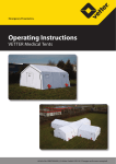
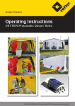
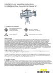
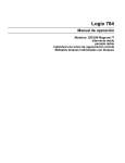
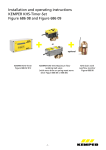
Installation and operating instructions
KEMPER ‘Control-plus‘ Hand-held measuring instrument
for sensors Figure 138 00 002
Table of Contents
1. General........................................................................................................................ P.2
2. Safety instructions ....................................................................................................... P.2
2.1 Hazards if the safety instructions are not complied with ............................ P.2
2.2 Safety-conscious work ..................................................................................... P.2
2.3 Safety instructions for the operating company/operator .............................. P.2
2.4 Unauthorized alteration and spare part fabrication ................................... P.2
2.5 Unauthorised modes of operation................................................................ P.2
3. Shipping and intermediate storage ............................................................................. P.3
3.1 Transport and shipping ..................................................................................... P.3
3.2 Intermediate storage ................................................................................... P.3
4. Technical properties .......................................................................................................... P.3
5. Functional elements/Scope of delivery ....................................................................... P.3
5.1. Description of scope of delivery .................................................................. P.3
6. Menu operation/function .......................................................................................... P.4
6.1 Control panel ............................................................................................... P.4
6.2 Switching on / Switching off / Battery saver mode ......................................... P.4
6.3 Power up with OK ............................................................................................. P.4
6.4 Measurement display window ...................................................................... P.4
6.5 Control, main menu ................................................................................... P.6
6.6 Control, units menu ................................................................................... P.7
6.7 Password protection .......................................................................................... P.7
7. ’Control-plus’ connection ........................................................................................... P.7
7.1 Connection with connection cable .............................................................. P.8
7.2 Sensor rating plate / Measurement range / Code letter .................................... P.8
7.3. Make measurement ..................................................................................... P.8
7.4 Allocation/Sensor measurement range ......................................................... P.8
8. Connecting ´Control-plus’ pressure sensor Figure 138 00 006................................................ P.10
8.1 Connection with connection cable .............................................................. P.10
8.2. Make measurement ..................................................................................... P.10
9. Measuring with the sensor measurement module ........................................................ P.11
9.1 Application ................................................................................................ P.11
9.2 Connection of measurement module and the hand-held measuring………… P.12
9.3 Structure of the measuring module menu .................................................. P.12
9.4 Measurement module configuration with Figure 138 4G, 638 4G ................. P.13
9.5 Measurement module configuration for Pt1000 .......................................... P.14
9.6 Measurement module configuration for Pt100 ........................................... P.14
9.7 Measurement module configuration for 0-20mA and 4-20mA .................... P.15
9.8 Measurement module configuration for 0-10V .......................................... P.16
9.9 Measurement module configuration for 0-500 Hz frequency signal ............ P.17
10. Datalogger function ................................................................................................ P.17
10.1 Save actual measurements function .......................................................... P.17
10.2 Function, single measurement .................................................................... P.17
10.3 Display saved values ................................................................................... P.18
10.4 Erasing the memory ......................................................................................... P.18
11. ’Control-plus’ software for PC evaluation .................................................................. P.18
11.1 Software installation .................................................................................. P.19
11.2 Connecting hand-held measuring instrument to PC .................................... P.20
11.3 General system settings .............................................................................. P.21
11.4 Formatting and saving measurements ........................................................ P.22
11.5 Measurement records ................................................................................. P.23
-1-
1. General
The KEMPER ´Control-plus’ Hand-held measuring instrument in combination with the KEMPER ´Control-plus’ flow and
temperature measurement valve Figure 138 4G and Figure 638 4G is used for precisely determining volume rates and
temperatures and for documenting the measurements in potable water, circuits for heater water, hot water
treatment and well water. The measured volumetric flow rate, the flow velocity in the pipe and the temperature are
shown on the graphic display and can be saved together with the date, time, and measuring point name. PC
evaluation of up to 4000 measurement data is facilitated through a USB interface with the PC evaluation software,
which is included in the scope of delivery.
In association with the KEMPER Sensor Measurement Module Figure 138 00 011, temperatures can be evaluated and
saved with the KEMPER Temperature sensors Pt1000 Figure T5100 140 00 003, Pt1000 Figure 628/629 0G and Pt100
sensors and general sensors signals with 4-20mA optionally 0-20mA or 0-10V.
The unit is designed state-of-the-art, manufactured with great care and underlies constant quality assessment. These
operating instructions are intended to easily familiarise yourself with the unit and to enable you to use its range of
applications as intended. The operating instructions contain important information needed to operate the device
safely, appropriately and economically. Be sure to comply with them in order to guarantee the unit's reliability and
service life and to prevent hazards. The operating instructions do not take the local regulations, with which the
operating company and the installation personnel it involves are responsible, into consideration. Never operate the
device above the stipulated values regarding supply voltage, ambient temperature, protection class and other
instructions stated in the operating instructions. If additional information or instructions are needed and in case of
damage, please contact
Gebr. Kemper GmbH + Co. KG,
Harkortstr. 5, 57462 Olpe,
Tel. 02761/891-0, Fax 02761/891-175,
E-Mail: [email protected]
2. Safety instructions
This safety data sheet contains basic instructions that must be complied with during storage, operation and
maintenance. That means it is mandatory to read the operating instructions before installation and commissioning.
2.1 Hazards if the safety instructions are not complied with
Non-compliance with the safety instructions can result in both hazards to people and hazards to the environment
and the device. Non-compliance with the safety instructions leads to the loss of rights to all compensation claims. In
particular, non-compliance can, for example, result in the following hazards:
Hazards to people through electrical and mechanical effects
Failure of important functions in the device
Failure of prescribed methods for maintenance and repair
2.2 Safety-conscious work
The safety instructions listed in these operating instructions and the existing domestic regulations regarding
accident prevention and any possible internal company work, operations and the safety regulations must be
observed.
2.3 Safety instructions for the operating company/operator
Exclude any hazard caused by electrical energy (see country-specific regulations and regulations of the
local power supply companies about this).
2.4 Unauthorized alteration and spare part fabrication
Alternations and modifications are only permissible after consultation with the manufacturer. Genuine spare parts
and accessories authorized by the manufacturer serve safety. It is explicitly pointed out that spare parts and
authorised accessories not supplied by the manufacturer have not been tested and are not approved by the
manufacturer. The installation and / or use of such products can therefore change the specified attributes of the
device in a negative manner under certain circumstances. All liability of the manufacturer is excluded when nonoriginal spare parts and accessories not authorised by the manufacturer are used!
2.5 Unauthorised modes of operation
Never exceed the limits stated in the following chapters.
-2-
3.Shipping and intermediate storage
3.1 Transport and shipping
The device must be properly shipped. The device was checked for compliance with all stated data before dispatching.
The device should therefore be in a flawless electrical and mechanical condition on arrival. To convince yourself of
that it is recommended to inspect the device for shipping damage upon acceptance. If there are any complaints
prepare a damage report together with the deliverer.
3.2 Intermediate storage
Intermediate storage must be dry and vibration-free in the original packing. The ambient temperature must not lie
outside the range of -0 to +50 °C.
4. Technical properties
- Volumetric flow display, optionally in: Litres/sec., Litres/min. (factory setting), Litre/h, m3/h, kg/h, kg/min.,
kg/sec. - Flow velocity display optionally in: m/sec (factory setting), m/min.
- Temperature display optionally in: 'C (factory setting), 'F, K
- Measurement input for ´Control-plus´ Flow and Temperature Sensor Valve, Figure 138 4G
- Measurement input for KHS flow sensor fitting Figure 638 4G
- Measurement input for KHS temperature measurement fitting Pt1000 Figure 628/629
- Measurement input for Temperature Sensor Pt100, Figure T5100 140 00 003
- Measurement input Temperature Sensor Pt100
- Measurement input 4-20mA optionally 0-20mA
- Measurement input 0-10 V
- Can save 4000 measurement data
- Measurement data storage optionally manual or as datalogger
- USB interface for PC link and measurement data analysis and evaluation
- Protection class IP65
- Size: 120x65x27
- Housing material: ABS, joint seal: TPE
- Device with permanently installed NiHM battery 5V/2Ah
- Battery charge current max. 500mA, charging time 4h
- Battery can be charged via USB interface with PC, USB power supply unit 230V (included in scope of delivery),
USB power supply unit 12V - Menu guidance in German, English or Dutch
5. Funktionselemente/Lieferumfang
1
2
3
1. Measurement cable input
2. Hand-held housing with surrounding joint seal
3. Graphic display with background lighting
4. Control via 4 keys: Up, Down, OK, Esc.
5. USB connection / Strap attachment
4
5
5.1 Description of scope of delivery:
- ´Control-plus’ Hand-held measuring instrument
- Carrying strap
- USB power supply unit 230V-5V
- ´Control-plus’ PC software
- USB adapter cable
- Control-plus’ M12x1 connection cable
Caution!
Before switching on the NiHM battery for
the first time, charge min. 4h with the USB
adapter cable and the 230V power supply
unit or a PC.
-3-
6. Menu control / "Display" "Menu" function
6.1 Control panel
The hand-held measuring instrument is set and controlled using a four key control panel.
1
2
Key 1 ESC:
Exit the menu – switch between display / main menu
Key 2 OK:
Acknowledgement key - switch between display / units menu
3
4
Key 3 :
Scroll back
Key 4
:
Scroll forward
6.2 Switching on / Switching off / Battery saver mode
Switch the device on by pressing the "OK" key > 1 sec.
Switch the device off by pressing the "Esc." key > 2 sec.
If no input is made for 60 sec. (factory setting, time can be set in the system settings), the device goes into the battery
saver mode and the display illumination is turned off. Press any key to switch the display back on.
If no input is made for 180 sec. (factory setting, time can be set in the system settings), the device switches off.
6.3 Power up with "OK"
1.
Press "OK" key for > 1 sec.
2.
KEMPER logo and the software version are displayed for approx. 5 sec.
3.
The display switches into the measurement display
6.4 Measurement display window
- Sensor measurements
3
o Volumetric flow rate options: l/sec., l/h, m /h, kg/h, kg/min, kg/sec
o Temperature options: °C , °F , K
o Volumetric flow rate options: m/sec , m/min
-sensor type /name
-battery status
-battery charging process
-PC- connection
-time/date
Measurement display, Example 1: Direct measurement with Figure 138 4G/638 4
Volume flow
Temperature
Battery
Sensor type
Scrollbars
Date / Time
Flow velocity
Battery charging
PC connection
-4-
Measurement display, Example 2: Measurements with measurement module and Figure 138 4G/638 4G
optional 16digit sensor
name
Measurement display, Example 3: Measurements with measurement module and various sensors
Temperature
Temperature Sensor
Valve Pt1000 Figure
Sensor measurement
Figure 138 00 011
Temperature
Plug-in temperature sensor
Pt1000 Figure T5100 140 00
e.g. pressure
General sensors
0 (4) – 20 mA
0- 10V
-5-
6.5 Operating main menu
1 x "Esc" switches from
measurement display into the
i
"Scroll back/forward": To
select the submenuc
Scrollbars – show
position in the menu
Arrows indicate the selected
1 x "OK" Changes into the
submenu
Scrollbars – show
position in the menu
Arrows indicate the selected
1 x "OK" Changes into the
submenu
Additional controls in the menu:
"Scroll back / forward":
Select in the menu
„OK“
Confirm point / change
„Esc“
back
E.g. to set times, dates
Arrow points to number
selected to
Scroll back/forward + "OK"
Set and confirm number
-6-
Arrow points to next
number selected to set
6.6 Operating units menu
1 x "OK" switches from display
into units menu
"Scroll back/forward":
To select the submenu
Scrollbars – show
position in the menu
Arrows indicate the selected
1 x "OK" Changes into the
submenu
6.7 Password protection
Password protection factory setting is 0000 and can be changed in the system settings menu.
The following functions are password protected:
- System settings/Load factory settings (resets all settings) -Data logger/Erase memory
(the entire memory is erased)
- Measurement module/Write in measurement module
(Configuration saved or overwritten in the measurement module)
- Measurement module /Load factory settings into measurement module
(Deletes the configuration in the measurement module)
7. Connecting ´Control-plus’ flow and temperature sensor valve Figure 138 4G/638 4G
Connection cable
M12x1
Sensor rating plate
with measurement
range
Sensor in the test section
Hand-held measuring instrument connected
-7-
7.1 Connection with 2m, M12x1 connection cable
The 2m, M12x1 ´Control-plus’ connection cable is required to connect the hand-held measuring instrument to
the flow sensor (included in the scope of delivery).
7.2 Sensor rating plate / Measurement range / Code letter
The correct sensor type 138 4G and 638 4G must be allocated to the appropriate measurement range in
the hand-held measuring instrument. The specifications for allocating are printed on the rating plate sensor
protection cap with the measurement range in l/min. and the code letter.
The related measurement range must be selected in the submenu item Figure 1384G/6384G.
After allocating the sensor in the menu, the volume flow, the temperature and the flow velocity
are shown in the display.
7.3 Make measurement
1. Use Esc in the main menu to switch (if not yet displayed in the main menu)
2. Select submenu Select Sensor
3. Select submenu Figure 1384G/6384G
4. Select the rating plate measurement range that corresponds to the sensor with the code letter
e.g. =>c<=
3.5-50l/min.
5. If applicable, enter the inside pipe ø; important for the flow velocity calculation
6. If applicable, enter the glycol proportions (The glycol additive changes the Qmin. of the sensor.
Comply with the installation and operating instructions Figure 138 4G and Figure 638 4G!)
7. Go back to measurement display
8. Measurement are shown
2X
OK
OK
1X
OK
1X
1X
OK
7.4 Allocating the sensor measuring range to the menu Figure 138 4G/638 4G
Rating plate 138 4G
Rating plate 638 4G
Figure 138 4G 015:
Measurement range
1,8-32l/min. ►b◄
Figure 138 4G 020:
Measurement range
3,5-50l/min. ►c◄
Figure 638 4G 015:
Measurement range
3,5-50l/min. ►c◄
-8-
Menu 138 4G/638 4G
Figure 138 4G 025:
Measurement range 5-85l/min. ►d◄
Figure 638 4G 020:
Measurement range 5-85l/min. ►d◄
Figure 138 4G 032:
Measurement range 9-150l/min. ►e◄
Figure 638 4G 025:
Messbereich 9-150l/min. ►e◄
Figure 138 4G 040:
Measurement range 12-216l/min. ►f◄
Figure 138 4G 050:
Measurement range 17-298l/min. ►g◄
-9-
8. Connecting ´Control-plus’ pressure sensor Figure 138 00 006
8.1 Connection with 2m, M12x1 connection cable
The 2m, M12x1 ´Control-plus’ connection cable is required to connect the hand-held measuring instrument to
the flow sensor (optionally available, both ends are marked yellow).
8.2 Make measurement
1. Use Esc in the main menu to switch (if not yet displayed in the main menu)
2. Select submenu Select Sensor
3. Select submenu Figure 138 00 006
4. Go back to measurement display
5. Measurement are shown
2X
OK
OK
- 10 -
1X
9. Measuring with the sensor measuring module Figure 138 00 011
Measurement module
Accessory part
If applicable, constructionsite cable extension
M12 x 1 cable with loose strands
for connecting Figure 138 4G/638 4G
Accessory part Figure 138 00 012
D-Sub cable 9-pin 1:1
Scope of delivery
Hand-held measuring
instrument
9.1 Application
The KEMPER Sensor Measurement Module is used to read out measurement data, in combination with
the hand-held measuring instrument, which originate in a sensor in, e.g., an inaccessible installation area.
The sensor values can be downloaded and saved with the Hand-held Measuring Instrument (Figure 138 00 002)
by using a plug connector on the Sensor Measuring Module (the cable is included in the scope of delivery of the
hand-held measuring instrument).
The measurement display on the hand-held measuring instrument appears optionally depending
on the sensor selection.
The following settings can be made with the hand-held measuring instrument and can be saved in
the measurement module:
- 16-digit module name, e.g., the location of the measuring point
- Sensor type and measurement range, e.g. Figure 138 4G, measurement range =>c<= 3.5-50 l/min.
- Cable compensation for the 2-conductor temperature measurement
- Setting min./max. Values with unit of measure proportional t the measurement range at 0 (4)-20mA / 0-10V
After configuring the measurement module and reconnecting the hand-held measuring instrument, the sensor
values are always shown, without having to make new settings, directly on the display and can be saved with the
datalogger. The configuration can be adapted and changed with the hand-held measuring instrument.
All Pt temperature measurements with Figure 138/638 4G, Figure 628/629 and Figure T5100 140 00 003 are
evaluated by the hand-held measuring instrument as 2-conductor measurements. The measurements will
be falsified by the cable resistance.
With a 10 m cable length with 0.34 mm2 cable cross-section, the falsification of the temperature measurement
can already amount to as much as approx. +0.5°C.
It is recommended to equalise the resistance deviations caused by the cable extensions from the temperature
sensor to the measurement module with the cable compensation menu item.
The hand-held measuring instruments automatically calculates the right (correct) temperature after making
the following possible entries.
Possible entry for the cable compensation for the 2-conductor temperature measurement
- Cable length x cross-section
- Resistance offset
- Temperature offset
The KEMPER Sensor Measurement Module is designed for permanent connection to one each of the
following sensors:
- 11 -
- KEMPER ´Control-plus´ Flow and Temperature Sensor Valve, Figure 138 4G
- KHS Vortex Flow Sensor, Figure 638 4G
- KHS Pt1000 Temperature Sensor Valve, Figures 628/629
- Temperature Sensor Pt100, Figure T5100 140 00 003
- Any sensor with 4-20 mA optional 0-20 mA output
- Any sensor with 0-10V output
9.2 Connection of measurement module and the hand-held measuring instrument
To be able to make the configuration in the measurement module menu, the hand-held measuring instrument has to
be connected to the D-Sub cable (included in the scope of delivery) and the measurement module.
The menu item is greyed out in the main menu if there is no connection.
Connection established
Settings can be made
No connection established
Settings cannot be made
9.3 Structure of the measuring module menu
1. Enter 16-digit module name
2. Select connected sensors: e.g., Figure 138 4G/638 4G, Pt1000, Pt100 etc.
3. Settings of connected sensors: Sensor type and measurement range, cable compensation, etc.
4. Important! Write in the measurement module: The settings will be applied to the measurement module
To permanently save the configuration set in the hand-held measuring instrument to the measurement module,
after entering the sensor settings the function "Write in Measuring Module" must be carried out. If you do not carry
out the writing and the measurement cable or the hand-held measuring instrument is pull off, you will have to reenter the sensor settings for additional measurements.
5. Read from the measurement module: The settings will be applied from the measurement module to the
hand-held measuring instrument
6. Store in clipboard: Settings will be stored from the hand-held measuring instrument to the clipboard
7. Load from clipboard: Settings will be copied from the clipboard into the hand-held measuring instrument
8. Load factory measurement module settings: The measurement module memory is reset
1
4
2
3
5
6
7
- 12 -
9.4 Measurement module configuration for Flow and Temperature Sensor Valve, Figure 138 4G, Figure 638 4G
1. Use Esc in the main menu to switch (if not yet displayed in the main menu)
2. Select measuring module submenu
3. Enter module name, e.g. ROOM -3.0
4. Sensor selection: Sensor 138 4G/638 4G
5. Settings:
- Select measurement range, e.g. measurement range =>c<= 3.5-50 l/min.
- If applicable, enter inside pipe ø, important for the flow velocity calculation
- If applicable, enter the glycol proportions (The glycol additive changes the Qmin. of the sensor.
Comply with the installation and operating instructions Figure 138 4G and Figure 638 4G!)
- If applicable, enter the cable compensation: e.g. Cable length x Cross section
6. Save measurement module / Settings will be saved to the internal measurement module memory
7. Return to measurement display... / Jumps directly to the measurement display
2X
OK
OK
OK / ESC
OK
1X
OK
OK
z.B.1 X
OK
1X
1X
1X
1X
OK
1X
OK
OK
- 13 -
9.5 Measurement module configuration for Temperature measurement fitting Pt1000
Figure 628 0G and 629 0G and Temperature sensor Pt1000
Pt1000, Figure 628/629 0G
Pt1000, Part no. T5100 140 00 003
1. Use Esc in the main menu to switch (if not yet displayed in the main menu)
2. Select measuring module submenu
3. Enter module name, e.g. ROOM -3.0
4. Sensor selection Pt1000
5. If applicable, enter cable compensation: e.g. Cable length x Cross section
6. Save measurement module / Settings will be saved to the internal measurement module memory
7. Return to measurement display... / Jumps directly to the measurement display
2X
OK
OK
OK / ESC
OK
1X
1X
OK
OK
1X
OK
9.6 Measurement module configuration for Pt100
1. Use Esc in the main menu to switch (if not yet displayed in the main menu)
2. Select measuring module submenu
3. Enter module name, e.g. ROOM -3.0
4. Sensor selection Pt100
5. If applicable, enter cable compensation: e.g. Cable length x Cross section
6. Save measurement module / Settings will be saved to the internal measurement module memory
7. Return to measurement display... / Jumps directly to the measurement display
2X
OK
OK
OK / ESC
OK
1X
- 14 -
OK
1X
1X
OK
OK
9.7 Measurement module configuration for 0-20mA and 4-20mA
1. Use Esc in the main menu to switch (if not yet displayed in the main menu)
2. Select measuring module submenu
3. Enter module name, e.g. ROOM -3.0
4. Sensor selection 0-20mA or 4-20mA
5. Stipulate value at (0)4 mA, 20mA and unit of measurement e.g. 4mA / 0.5 bar and 20mA / 10bar
6. Save measurement module / Settings will be saved to the internal measurement module memory
7. Return to measurement display.... / Jumps directly to the measurement display
2X
OK
OK
OK / ESC
OK
1X
OK
OK
OK
OK
OK
OK
OK
OK
OK
OK
OK
OK/ESC
OK
OK
OK
- 15 -
OK
9.8 Measurement module configuration for 0 – 10V
1. Use Esc in the main menu to switch (if not yet displayed in the main menu)
2. Select measuring module submenu
3. Enter module name, e.g. ROOM -3.0
4. Sensor selection 0-10V
5. Stipulate value at 0V, 1 0V and unit of measurement e. g. 0V / 0.5 bar and 1 0V / 1 0bar
6. Save measurement module / Settings will be saved to the internal measurement module memory
7. Return to measurement display... / Jumps directly to the measurement display
2X
OK
OK
OK / ESC
OK
1X
OK
OK
OK
OK
OK
OK
OK
OK
OK
OK
OK
OK/ESC
OK
OK
- 16 -
OK
9.9 Measurement module configuration for 0-500Hz frequency signal, square wave signal min. 3V – max. 24V
1. Use Esc in the main menu to switch (if not yet displayed in the main menu)
2. Select measuring module submenu
3. Enter module name, e.g. ROOM -3.0
4. Sensor selection
5. Stipulate value at 0V, 1 0V and unit of measurement e. g. 0V / 0.5 bar and 1 0V / 1 0bar
6. Save measurement module / Settings will be saved to the internal measurement module memory
7. Return to measurement display... / Jumps directly to the measurement display
2X
OK
OK
OK / ESC
OK
1X
OK
OK
OK
10. Datalogger function
10.1 "Save actual measurements" function (single measurement)
1. Use Esc in the main menu to switch (if not yet displayed in the main menu)
2. Select datalogger menu
3. Single measurement function, select save actual measurement
4. Enter optional no of the measurement
5. Data record is saved
OK
1X
OK
OK
10.2 Single measurement function "Start long-term measurement"
1. Use Esc in the main menu to switch (if not yet displayed in the main menu)
2. Select datalogger menu
3. Select Long-term measurement function
4. Enter interval of permanent measurement
5. Enter start and end of measurement, e.g. Start: immediately, End of measurement: Memory full
6. The long-term measurement can be exited at any time
7. In the measurement display, the measurements alternate with the "Long-term measurement" information
1X
OK
1X
OK
7 x OK
OK
- 17 -
OK
ESC
10.3 Display saved values
1. Use Esc in the main menu to switch (if not yet displayed in the main menu)
2. Select datalogger menu
3. Select Display saved values menu
4. View measurements: OK key switches the displayed measurements, and
5. Use ESC to exit the menu again
ESC
keys view permanent
1X
OK
2X
OK
OK
z.B. 8 X
OK
10.4 Erasing the memory
The memory needs to be manually erased if the display indicates "Free memory 0%" has been reached.
1. Use Esc in the main menu to switch (if not displayed in the main menu)
2. Select datalogger menu
3. Select menu Free memory xx%, erase memory?
4. Enter password and confirm with OK (factory setting 0000)
5. Use ESC to exit the menu again
1X
OK
3X
OK
4 x OK
1X
11. 'Control-plus' software for PC evaluation
The ´Control-plus’ PC software facilitates connecting and activating the customer's PC to the hand-held
measuring instrument. The stored measurements can be read out of the hand-held measuring instrument
with the software and saved in a csv file. The current software version is available under www.kemperolpe.de.
- 18 -
11.1 Software installation
PC system requirements:
Windows XP or higher, monitor resolution min. 1024 x 600, one free USB port
1. Insert CD ROM in a PC-CD ROM drive
2. Start start.exe
3. Confirm welcome message with OK
4. Start installation with PC button
5. Confirm Kemper program group with next
6. Confirm completion of installation with OK
7. Open software under: Start – Programs – Kemper – KEMPER ´Control-plus’
8. Create desktop shortcut with Yes.
- 19 -
9. Install USB driver with Yes
10. In the status window, the software indicates in red letters that no connection has been
established to the -MASTER-.
11.2 Connecting hand-held measuring instrument to PC
USB cable
Hand-held measuring instrument
scope of delivery
- 20 -
After connection, the status window displays the word CONNECTED in green letters
11.3 General system settings
The following general system settings can be made in the middle box.
1. Language selection: Select the language for the PC software desktop
2. Time and date: Apply from PC to the controller, automatic daylight savings time / standard time
switchover enabled or inactive
4.
Select the unit display in the flow, temperature and velocity record
1
2
3
- 21 -
11.4 Read and save measurement formatted data from the hand-held measuring instrument
1. Select units for test record
2. Read the measurements from the device
2
1
3. Wait until all data have been completely read. Acknowledge message
3
5.
Save measurements in csv file
4
5. csv file open with Excel
- 22 -
11.5 Test record in the csv format
Test record
Measuring point
Sensor
Measurement range
Pipe DN
Glycol proportion
2.04
1384G DN20
=>c<=
19.6
0
in mm
in %
Measurement
No.
Date
Time
1
1
15.12.2009
09:39:06
Flowrate
[l/min]
10,08
Speed
[m/sec]
0,56
PT1000
[°C]
56
Flowrate
[l/min]
10,28
10,28
10,28
10,28
10,28
10,28
10,09
10,28
10,28
10,27
Speed
[m/sec]
0,57
0,57
0,57
0,57
0,57
0,57
0,56
0,57
0,57
0,57
PT1000
[°C]
55,1
55,1
55,2
55,2
55,2
55,2
55,2
55,2
55,2
55,2
Test record
Measuring point
Sensor
Measurement range
Pipe DN
Glycol proportion
2.04
1384G DN20
=>c<=
19.6
0
in mm
in %
Measurement
No.
Date
Time
2
2
2
2
2
2
2
2
2
2
1
2
3
4
5
6
7
8
9
10
15.12.2009
15.12.2009
15.12.2009
15.12.2009
15.12.2009
15.12.2009
15.12.2009
15.12.2009
15.12.2009
15.12.2009
09:39:19
09:39:20
09:39:21
09:39:22
09:39:23
09:39:24
09:39:25
09:39:26
09:39:27
09:39:28
Test record
Measuring point
Pt1000
Measurement
No.
Date
Time
3
1
15.12.2009
09:39:51
PT1000
[°C]
58
Test record
Measuring point
1.03
No.
Date
Time
4
1
15.12.2009
09:40:13
K410013800002-00 10/12
Technical subject to change.
Measurement
Gebr. Kemper GmbH + Co. KG
Metallwerke
Harkortstr. 5
D-57462 Olpe
Tel. 0 27 61 - 8 91 - 0
Fax 0 27 61 - 8 91 -1 75
[email protected]
www.kemper-olpe.de
- 23 -
PT100
[°C]
57,6