1
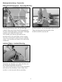
Bedienungsanleitung
GB
Operating instructions
IE-XM-RJ45/IDC
8808360000
Montagevorbereitung • Preparation
Erdung/Potentialausgleich • Grounding/Earthing
Erdungskontaktfeder
grounding contact spring
Die Erdung der Module erfolgt über die
Erdungskontaktfeder direkt auf die Montageschiene. Diese wird durch eine Erdungsklemme
mit dem Potentialausgleich verbunden. Montageschiene muss elektrisch leitend sein.
The modules are directly grounded to the
mounting rail by the grounding contact spring.
The rail is connected to earth using an earthing
clamp. The mounting rail needs to be electrically
conductive.
Anschließend das Gehäuseunterteil des
IE-XM-RJ45/IDC auf die Montageschiene rasten.
Then click the lower housing part of the
IE-XM-RJ45/IDC onto the rail.
Isolierter Einbau • Isolated Mounting
Soll das Modul nicht geerdet werden, den
Rasthaken am Gehäuse nach unten drücken und
die Erdungskontaktfeder entnehmen.
Press the mounting latch at the housing downward
and remove the grounding contact clamp if the
module is to be mounted without grounding.
2
Kabelkonfektion • Cable Preparation
m
30 ax.
mm
4
Paar-Schirmfolie einkerben und entfernen.
Cut and remove the shield foil of the wire pairs.
Kunststoffmantel ca. 25 mm (max. 30 mm)
abisolieren.
Remove about 25 mm (max. 30 mm) of the
plastic sheath.
Kabelseite1/cable end1
weiß/orange
white/orange
weiß/braun
white/brown
Kabelseite2/cable end2
weiß/blau
white/blue
5
Je nach Austritt des Kabelendes Adernpaare
separieren . . .
Separate the wire pairs on each end according
to their exit from the sheath . . .
. . . und gleichmäßig um den Kunststoffmantel
drehen.
. . . and wrap it evenly around the plastic sheath.
weiß/grün
white/green
weiß/orange
white/orange
weiß/blau
white/blue
weiß/blau
white/blue
Kabelseite2/cable end2
weiß/braun
white/brown
weiß/orange
white/orange
6
weiß/grün
white/green
Kabelseite1/cable end1
5m
m
weiß/braun
white/brown
Geflechtschirm nach hinten legen . . .
Fold braided shield backwards . . .
3
weiß/braun
white/brown
weiß/grün
white/green
weiß/orange
white/orange
weiß/blau
white/blue
2
weiß/grün
white/green
1
. . . und nach dem Bild anordnen, um die Adern
später leichter in das Ladestück einführen zu
können.
. . . and arrange the pairs as shown on the
photos to facilitate insertion to the loader.
3
Kabelmontage • Cable Connection
7
10
7 weiß/white
8 braun/brown
3 weiß/white
6 orange/orange
Die Adernpaare weiß/braun und weiß/orange in die
unteren Öffnungen des Ladestücks einführen . . .
Insert the wire pairs white/brown and white/orange
in the lower wire guides of the loader . . .
8
Zum Entfernen der überstehenden Adern einen
geeigneten Seitenschneider verwenden . . .
Use an appropriate wire cutter to cut the excess
length of the wires . . .
11
4 blau/blue
5 weiß/white
2 grün/green
1 weiß/white
. . . die Adernpaare blau/weiß und grün/weiß
oben in das Ladestück einlegen.
. . . and the wire pairs blue/white and green/white
in the upper wire guides of the loader.
. . . und die Kabeladern bündig abschneiden.
. . . and cut the wire ends flush.
12
9
Kabelbinder zur Zugentlastung anbringen und
Überlänge entsprechend abschneiden.
Fit a cable tie and cut off the excess length.
Mit einem ungeeigneten Seitenschneider lassen
sich die Kabeladern nicht bündig abschneiden.
Dies führt zu Problemen beim späteren
Zusammenfügen der beiden Gehäuseteile.
The wires cannot be cut really flush with an
inappropriate wire cutter. Excess wire will cause
problems when the two housing parts are
assembled.
4
Montage der Module • Module Installation
13
16
Beim Zusammenfügen der Gehäuseteile, das
Ladestück gerade auf das Gehäuseunterteil
setzen.
When the two housing parts are assembled
make sure that the loader is correctly aligned
with the lower housing.
Das fertig angeschlossene Modul in das
Gehäuseunterteil einsetzen.
Insert the module into the lower housing part.
14
17
Eine Zange in der Modulmitte ansetzen und das Modul
zusammendrücken, bis das Gehäuse geschlossen ist.
Place pliers in the middle of the module and press until
the housing is closed.
Gehäusedeckel oben an das Gehäuseunterteil
einhaken und nach unten einrasten.
Hook the upper housing part at the top of the
lower housing part and click it downwards into
place.
15
18
Wird die Zange zu weit hinten angesetzt, kann
es passieren, dass das Ladestück verrutscht und
die Schneidklemmen im Inneren des Moduls
beim Zusammendrücken beschädigt werden.
If the pliers are placed too far back, the loader
may slip slightly and consequently damage the
ID contacts when the housing parts are pressed
together.
5
Demontage • Disassembly
19a
Öffnen des Gehäuses
Gehäuseoberteil mittels eines Schraubendrehers
lösen und entfernen.
Opening the Housing
Unclip the upper housing part with a screwdriver
and withdraw it.
Um den Potentialausgleich der Module zu
gewährleisten, muss die Montageschiene über
eine Erdungsklemme mit dem Potentialerder
verbunden werden . . .
To ensure the earthing of the modules the
DIN rail must be connected to earth using an
earthing clamp . . .
19b
. . . Hierzu diese einfach auf die Montageschiene
aufsetzen, festschrauben und am Potentialausgleich anschließen.
. . . Clip the earthing clamp on to the DIN rail,
fasten the screw and connect it to earth.
Entfernen des Moduls
Die Gehäusewände leicht nach außen drücken
und das Modul entnehmen.
Removing the Module
Press the housing walls slightly outwards and
remove the module.
6
Öffnen des Moduls • Opening the Module
Beschaltungshinweise • Pin/Pair Assignment
Beschaltung nach ISO/IEC 11801, EN50173
Bitte beachten Sie die Farbkodierung für die
Verdrahtung gemäß TIA/EIA-568A.
Pin/pair assignment according to ISO/IEC
11801, EN50173
Please note colour coding for wiring per
TIA/EIA-568A.
Ladestück mit einem kleinen, flachen
Schraubendreher entriegeln . . .
Unclip the loader using a small, flat-bladed
screwdriver . . .
. . . und beide Gehäuseteile voneinander trennen.
. . . and separate the two housing parts.
Mechanische Eigenschaften
Adernanschluss:
Schneidklemme IE-XM-RJ45/IDC:
Leiter 0,4– 0,65 mm
AWG 26 – 22 Isolation 0,7–1,4 mm (1,6 mm)
AWG 26/7 Litzenleiter mit 7-drähtiger
CU-Litze blank
Wiederverwendbar für AWG 22, AWG 23 und
AWG 24 bei Verwendung eines gleichen oder
größeren Querschnitts.
Mechanical Features
Wire termination:
IE-XM-RJ45/IDC:
wire 0.4 – 0.65 mm AWG 26 – 22
insulation 0.7–1.4 mm (1.6 mm)
AWG 26/7 bare stranded copper wire with 7 strands
Reusable for AWG 22, AWG 23 and AWG 24 when
using a wire with the same or bigger cross section.
7
Hinweis für Verwender und Monteure
Unsere Anschlusssysteme und Verteilerprodukte für strukturierte Gebäudeverkabelungen
entsprechen den gültigen Normen EN 50173-1:2002 und IEC 60603-7. Bei Komplettierung
der Anschlüsse muss der Verwender/Montagebetrieb prüfen und beachten, dass nur Patch- und
Anschlusskabel, die die EN-/ IEC-Normen erfüllen, verwendet werden. Lassen Sie sich ggf. vom
Lieferanten den Nachweis geben, dass die eingesetzten Kabel und Stecker der Norm entsprechen.
Die Verwendung von nicht normgerechten Komponenten bedeutet den Verlust der Mängelrechte auch
innerhalb der Lieferkette unserer Produkte. Bitte beachten Sie auch, dass keine starken mechanischen
Einwirkungen und Beanspruchungen beim Ein- und Ausstecken des Benutzerkabels nach oben, unten
oder seitlich auf den elektrischen Kontaktbereich der Steckverbindung (z. B. durch Ziehen am Kabel
u. a.) erfolgen. Für dadurch entstehende Schäden haften wir nicht. Bitte übergeben Sie diesen Hinweis
auch an den Endverbraucher.
Notes for user and installer
Our termination systems and patch products for generic cabling meet the active standards
EN 50173-1:2002 and IEC 60603-7. The user or installer has to check and take care to use solely
patch and termination cables that meet the EN-/IEC standards when completing the installation. If
necessary ask your supplier to certify that the installed cables and plugs meet the standards. The use
of non-standard components means the loss of rights accruing from defects even within the supply
chain of our products. Furthermore, please pay attention that the electric contact area of the plug
connection is not exposed to high mechanical effects or strain (e.g. by pulling the cable etc.) when the
user cable is plugged in or out upwards, downwards or sidewards. We do not take over liability for any
damage. Please give this note to end users, too.
Weidmüller Interface
GmbH & Co. KG
Postfach 3030
32720 Detmold
Telefon +49 5231 14-0
Telefax +49 5231 14-2083
[email protected]
www.weidmueller.com
032005/3.500/01/L/899032-04