1
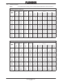
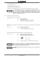
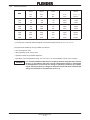
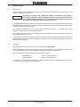
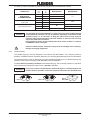
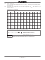
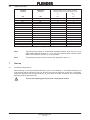
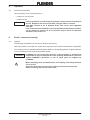
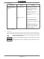
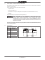
For drive by means of parallel keys the following fit pairs are prescribed for the bores:
Bore D1
Selection of fit
Shaft tolerances
to FLENDER standard
over
mm
25
to
mm
Shaft tolerances
25
k6
100
m6
100
50
System standard shaft
50
H7
n6
50
Shaft tolerances
to DIN 748/1
Bore tolerances
k6
H7
m6
50
all
K7
h6
M7
h8
N7
Table 6.1.1: Fit pairs
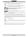
Caution!
The assigned fits must be adhered to in order, on the one hand, to keep the play
in the shaft-hub connection as low as possible, depending on utilisation of the
tolerance zones, or, on the other, to keep the hub tension arising from the
oversize within the permissible load limit. Failure to adhere to the fits may
impair the shaft-hub connection.
If the tolerance values of the shafts deviate from those in table 6.1.1 above,
FLENDER must be consulted.
Failure to observe these instructions may result in breakage of the coupling.
Danger from flying fragments!
6.1.2
Parallel keyway
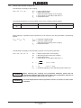
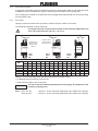
The parallel keyways must be designed in accordance with DIN 6885/1. If the keyway geometry
deviates, FLENDER must be consulted. Taper keys or nose keys (gib headed keys) are not permissible.
The parallel keyways must be designed to suit the available parallel keys. For parallel keyways the
tolerance zone of the hub keyway width ISO JS 9 must be adhered to.
For more difficult operating conditions of the kind arising e.g. with reversing operation or operation
with impulses the hub keyway tolerance zone ISO P9 is specified.
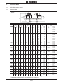
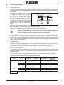
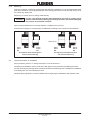
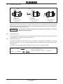
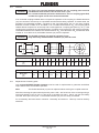
Caution!
Part 1
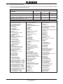
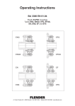
In the case of part 1 the parallel key must be brought in centrally between the
element lands or pockets, in the case of part 5 underneath the threaded bore.
Part 1 DS
BA 3101 EN 07.03
Part 5
Part 5 DS