1
Original
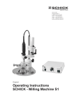
Operating Instructions
SCHICK - Milling machine S2 Master
Index
We are pleased that you decided to buy a highly
developed piece of equipment from SCHICK and
would like to wish you every success when working
with your new milling machine S2 Master.
We wrote these operating instructions to enable
you to get accustomed to your new piece of
equipment and to provide you with the correct
operating and maintenance instructions.
Index
Page
1. List of contents ................................................................................................ 3
2. Range of applications....................................................................................... 4
3.
!
General information / Safety information................................................... 4-5
4. Installation and setting up................................................................................. 6
5. Picture milling machine S2 Master / operating elements.................................... 7
6. short instruction into operation......................................................................... 8
7. Operation......................................................................................................... 9-12
7.1 Milling arm/jointed arm
7.2 Magnetic table
7.3 Motor technology
8.
Exchanging the rotary instruments ...................................................................13
9.
Replacing the chuck. ........................................................................................13
10. Maintenance and care......................................................................................14
14
11. Possible faults...................................................................................................
15-16
12. Technical data / accessories./ ceramic set...........................................................
17
13. Declaration of conformity..................................................................................
2
List of contents
art.-no.
Serial parts
milling machine S2 Master complete
consisting of
2700/5
milling machine S2 Master
2705/5
C2 Motor incl. milling spindle and cable
6600/09
light equipment
2510
mains cable
2160
collet chuck Ø 2,35 mm
stroke for short tools
4114
4918
chuck key
4115
counter stay wrench
6223
dust protection cover
2794
optionally:
collet chuck Ø 3 mm
stroke for short tools
4117
4925
3
Range of Applications / General information
2. Range of Applications
The S2 Master milling machine is designed for use in dental laboratories
when trimming crowns and bridges, respectively acrylic and chrome cobalt dentures.
Highest precision and quality and minor maintenance are the merits
of the S2 Master which has been developed by experts in milling technics.
Conditions of environment:
- interior 5° - 40°
- up to 2.000 meter over sea level
Categorie of overvoltage: II
Grade of pollution: 2
3. General Information/Safety informations
- Ascertain that your mains supply coincides with the data in the rating
plate
- The milling machines S2 Master are not suitable for the following applications:
- in areas where there is a risk of explosion
- for medical applications
- Ensure that all regulatory requirements are observed during use (always waer
protective glasses).
- Under no circumstances should the milling machine be cleaned with
compressed air
- To keep the precision and the lifetime of the chuck always insert a rotary instrument
or the pin, supplied with the unit, page 13 (6) - even if the motor stands still.
- Recycling
WEEE-Reg.-Nr. DE 78620387
4
Safety informations
ATTENTION::
!
- Water-cooled turbines are only indicated to use in connection with a SCHICK
suction tub to avoid defects at the elctrical equipment and corrosion.
- When using rotary instruments, do not exceed the maximum speeds laid
down by their manufacturer.
- Repairs and other technical procedures must only be carried out by suitable
qualified personnel, authorized by SCHICK.
- SCHICK do not guarantee the S2 Master milling unit should it not have
been used in accordance with the operating instructions
- For defects occured by using the S2 Master milling machine in another way
or by inappropriate handling the manufacturer rejects any liability.
These operating instructions should be readily accessible and are best kept
close to the milling machine itself!
5
Installation and setting up
4. Installation
- Check the package for visible damages
- When unpacking handle all parts of consignment with care.
- Remove carefully the upper part of the inside package (withdraw
slowly (pict.. 1).
Please look that parts of the milling machine do not become
wedged with the package.
pict. 1
- Remove cartons containing accessories (pict.2)
Please look for the milling arm being fixed.
- Hold the milling machine at the column
Do not hold at the milling arm !
- Withdraw the machine a little bit and then hold
it at the basic plate to take the milling machine out.
pict. 2
- Check all parts for visible damages. Place all parts of inner
package back into the outer carton.
Store the complete package for an eventual return to manufacturer.
If you should intend to destruct the package, please be so kind
to return the complete package to SCHICK.
Setting up
The S2-Master is equipped with adjustable stands. When using a level
for telescopic crowns, the S2-Master has to be calibrated exactly with
a spirit level by screwing the stands clockwise or anti-clockwise.
Connect the milling machine with the mains supply by placing
the mains cable at first into the socket situated on the back
side of the milling machine and then into a safe wall socket
with earth connection.
Please check that all plug connections are readily fixed !
6
Picture Milling Machine
5. S2 Master
11
12
10
13
9
8
7
6
14
15
5
4
3
2
1
16
17
18
7
1.
2.
3.
4.
5.
6.
7.
8.
9.
10.
11.
12.
13.
14.
15.
16.
17.
18.
digital indicator
speed selection
switch “Magnet-EIN/AUS”
switch “Motor-EIN/AUS”
switch “Motor-R/L”
clamping lever jointed arm
tension lever
lever
clamping lever milling arm
knurled nut depth fixation
fine adjustment depth stop
clamping lever jointed arm
adjusting knob jointed arm
knurled nut milling spindle
knurled nut light attachement
magnetic table
adjustable stands
mains switch
Short instruction into operation
6. Short instruction into operation
activate mains switch (18)
milling arm
jointed arm
- Fastening and loosening with clamping lever (6)
- loosen clamping lever (12); for height adjustment use handwheel (13)
- position of clamping lever can be adjusted at any position desired by
pulling and turning
vertical arm
- adjust vertical arm at any position using clamping lever (6)
- use lever (8) to draw spindle down
fine adjustment through micrometer spindle (11)
milling spindle
- tension lever (7) showing to the left when chuck is closed
operating unit
- motor on/off with swith „Motor - EIN/AUS“ (4)
- speed adjustment variable with speed selector (2) - digital indicator (1)
- magnet on/off with swith „Magnet - EIN/AUS“ (3)
- changing rotation of milling spindle by using switch „Motor - R/L“ (5)
Important!
Detailed description see point 7 „Operation“
8
Operation
7. Operation
To activate the electric press mains switch (18) „I/O“.
Now all electric functions are controllable. To switch the unit off press mains switch (18) again.
7.1 milling arm/jointed arm
15
16
9
The milling- and the jointed arm has 2 joints for an absolutely free moving space.
To fix the milling arm on the horizontal plane you can use the levels (6+9),
therefore it is possible to make bores and to fix.
6
pict. 1
10
For a delicate vertical movement of the spindle with fixed hinges loosen the
knurled nut (10) and use the lever (8). With the vernier (11) the maximum travel to
depth can be restricted. This assures exact guidance when drilling Interlooks.
9
108
8
38
11
pict. 2
31
If, for example, the milling spindle should be fixed in a deep position when
fixing a part of an attachment, the milling arm has to be moved downwards
(see pict. 3) at the spring mounted the guide bar. Then the position can be fixed
with the knurled screw (10).
12
pict. 3
13
9
Operation
milling spindle
14
15
12
To remove the milling spindle detach light equipment and loosen knurled nut
(14) (pull spindle out upwards). To detach the light equipment loosen knurled
nut (15) (pict.1) and pull light equipment carefully down.
Put light equipment on again in reverse order.
When replacing the milling spindle pull down until stop.
Please pay attention that the thread pin placed in the spindle
holder clicks into the notch at the milling spindle.
17
The lever (7) (pict.2) at the milling spindle has to show into the left
direction. Tighten knurled nut (14).
pict. 1
Function of milling spindle see see on page 11.
12
13
Height adjustment
To adjust the height of the milling arm fist loosen the lever (12).
Then using the adjusting knob (13) to put the milling arm up or down
according to your needs.
pict. 1
7
pict. 2
measuring spindle
The measuring spindle (pict. 3) is supplied as accessory and can be placed
into the spindle holder in the same way as the milling spindle.
pict. 3
10
Operation
5
Direction of rotation of milling spindle
To change direction of rotation of milling spindle use switch
„Motor - R/L“ (5). If motor is running the direction right or left is shown
through a green light in the switch. It is also possible to change the
direction of rotation when motor is running.
23
7.2 magnetic table
39
magnetic platform
16
To fix the model table or other accessories in the center of the
magnetic platform an electro-magnet is placed (16) which is operated
via the switch „Magnet EIN/AUS“ (see page 7; no. 3).
To clear the platform you can easily take away the particles with a brush
through the paralle grooves.
11
Operation
7.3 motor technology
26
25
28
27
24
The milling unit S2 Master is equipped with the C2 technology.
This means extrem and stable torque in all speed ranges, silent and
vibration free running and highest balance.
With its 40.000 r.p.m. and 240 watt power the C2 milling spindle
masters even the hardest grinding and milling.
Attention: Use only tools which are in accordance to the
working speeds!
Maintenance of motor and spindle see „Maintenance and Care“
(point 10; page 14)
The integrated light equipment guaranties excellent illumination and
visibility of the working area.
Due to the direct connection with the milling spindle it‘s not necessary
to place the light always into the right position. Light exactly where
it is needed. The light equipment is joined with a plug connection
and can easily be removed and attached. The light intensity can be
adjusted by the dimmer knob (see page 6).
40
Please be informed that the light luminesces a little after
switching off the milling unit.
Removal of light equipment see „Operation - milling spindle“
(point 7.1; page 10)
12
Exchanging the rotary instruments
Replacing the chuck
8. Exchanging the rotary instruments
The chuck is opened by turning tension lever (7) to the right till it stops.
When the shaft of the rotary instrument is placed into the chuck turn tension lever
to the left till it stops.
With regard to the precision and service-life of the chuck, an instrument or the pin (6)
must always be inserted into it - even when the spindle is not in use.
.
!
CAUTION: Only ever exchange the rotary instrument with
the motor switched off! Risk of damage !
9. Replacing the chuck
- Take milling spindle out of the spindle holder
see “Operation - Milling Spindle” (point 7.1; page 10)
- Open chuck and remove the rotary instrument.
- Remove motorcable. Unscrew cap (1) from motor and loosen cable by pulling out the
plug-in seal (2) Please insure that the chuck is open.
- Use a number 6223 wrench (3) to hold the motor end of the spindle.
- Engage the triangular section of the chuck (5) with a number 4115 tool (4)
Hold tight No. 6223 (3) wrench and screw out the chuck by turning the
tool no. 4115 (4) anti-clockwise. The chuck has a right-handed thread !
Please note: In the chuck is a stroke for short shafts, this could be removed
or replaced as required.
- Clean the chuck, grease its outside lightly and place it in the spindle.
Use the tools as described to screw the chuck in - clockwise and as far as possible
and tighten it slightly. Replace the plug-in seal (2) and screw the cap (1) back
into place.
- Replace milling spindle in spindle holder.
4
6
5
chuck 2,35/3,0
(art.-no. 4114/4117)
stroke for chuck 2,35/3,0 (art.-no. 4918/4925)
7
13
3
2
1
Maintenance and care
Possible faults
10. Maintenance and care
!
CAUTION!: Do not clean milling machine and milling spindle with compressed air!
The chuck should be cleaned and re-greased once in a while, depending on how dirty it is
see “Replacement of chuck” (point 9; page 13)
- As the C2 milling spindle has no commutators, carbon brushes or ventilation parts,
no further maintenance is required.
- All guideways are maintenance free.
For cleaning please use only a brush!
Before cleaning please switch the milling machine off and withdraw mains plug !
11. Possible faults
- Should the milling spindle be overloaded, respectively, jammed, for safety
reasons the unit will switch off.
- turn speed selection (2) back to “0-postion”; select the desired speed and the
machine is ready for use again.
- alternatively switch mains switch (18) off and on again.
If after that the machine is not working please check the fuses and replace them if necessary.
The fuses (230V→ 2x T2AH250V art.no.:3106) (100-115V 2x T4AH art.no.: 7306) are to
be found beside the socket for the mains cable.
Should it not be possible to abolish the faults please contact SCHICK directly
14
Technical data / Accessory
12. Technical data
Rated voltage:
Rated frequency:
Torque Motor:
Speed range:
Concentricity:
230V / 115V / 100V
50 / 60 Hz
5,5 Ncm
2.500 - 40.000 min
< 0,015mm
Chuck:
- 2,35 mm standard
incl. stop for
short tools
- 3,00 mm as option
Width:
Height:
Depth:
Weight:
275 mm
485 mm
400 mm
16 kg
Subject to technical modification without prior notice
Accessory
Model table
Art.-No.
Adjustable angle
2407
Art.-No.
2506
Measuring spindle
Art.-No.
2250/1
Koordinate table
Art.-No.
Holding tray
2505
Milling set 2,35 mm
(7 pcs.) Art.-No. 2530
15
Art.-No.
2509
Milling tray
Art.-No.
2507
Adaptor
Art.-No.
.
2508
Accessory / Ceramic set
Ceramic set S2 Master
turbine
separator
Art.-No.
2640/1
Art.-No. 2655
Polish set Ø 2,35 mm
(3 pieces) Art.-No. 2665
model table stainless steal
suction tube
Art.-No . 2470/5
Art.-No.
2407/9
light head for turbine
Art.-No. 2510/1
Diamond Tool Set for
Turbine Ø 1,6 mm
(8 pieces) Art.-No. 2660
S2 - Ceramic milling set complete
(without milling unit)
turbine T100
adapter
holding clip
lighthead for turbine
suction tube
separator
model table stainless steal
Art.-No. 2650/05
Art.-No. 2640/1
Art.-No. 2481
Art.-No. 2793
Art.-No. 2510/1
Art.-No. 2470/5
Art.-No. 2655
Art.-No. 2407/9
16
Declaration of Conformity
13. Declaration of Conformity
We, SCHICK GmbH
Lehenkreuzweg 12
D-88433 Schemmerhofen
declare herewith, that the product
Milling machine S2 Master
Art.-Nr. 2700/5
is in conformity with the following provisions of Directive:
2001/95/EG
2006/42/EG
2006/95/EG
2004/108/EG
Name and adress of
person in charge:
(general product safety)
(machinery directive)
(low voltage directive)
(EMV directive)
Wolfgang Schick
Lehenkreuzweg 12
88433 Schemmerhofen
Schemmerhofen, September 2010
W. Schick
Geschäftsführer
D20995
10/13 bg
17