1
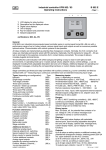
industry controller KFM 94 / KFM 95
operating instructions
B 9400 E
Page 1 of 8
3
1
1
2
3
4
5
6
Digital display actual value
2nd digital display (if aktive)
LED-display relais function
Key for setpoint and parameter mode
Setpoint adjustment
Parameter mode lock switch (back face)
2
6
4
5
Brief description:
KFM 94 is a microprozessor based industry controller series in panel mounting- format 72 x 144 mm.
Design and operating elements are especially devised for easy and convenient handling and operation.
An assembly system renders possible the simple basic version as well as a plurality of variants with
up to 6 relays, several digital and analog out- and inputs and other additional devices.
Inputs:
Types: (depending on configuration*):
type:
max. 4 measuring inputs, acc. to sub-type:
type suffix
indicator
9401.
Pt100 DIN, 0...400°C
none (or 0)
one stage controller
9410.
Pt100 DIN, 0...100°C
1.
two stage controller
9420.
thermo couple Ni Cr NI (type K)0...1200°C
n.
heating / cooling controller
9430.
thermo couple Fe Cu NI (type J)0... 900°C
f.
positioner / follow-up controller
9440.
thermo couple Pt Rh Pt (type S)0...1700°C
p.
two- point- PID controller
9450.
w.
feedback device 0...100 up to 1000 Ω
three- point- PID controller
9460.
standard signal 0(4)...20mA, 0(2)...10V
e.
three- point- step controller
9470.
Ranges:
continuous controller
9480.
Pt 100: 0...400°C, switchable to °F, optional: other
continuous controller, 2 outputs
9481.
Sub-types:
suffix (*) ranges; for standard signal range adjustable -999 to
4000. Setpoint ranges can be limited by menu
basic function
.0
Displays:
basic function + 1 additional contact
.1
2 four- figured digital displays, decimal point
basic function + 2 additional contacts
.2
adjustable, upper display: actual value, lower
2 x basic function
.3
display: other selectable data,
extension: (continuous) logic output
..L
function extensions
suffix (*) up to 8 LEDs for relays function display.
Display of function:
cascade controller
991k
Hold down the P-key for more than 5 sec
program controller
991p
to get a short-cut message of the configured function on
ramp set point value
991r
the display (=position 3-5 of list number)
step controller
991t
(in case of locked parameter mode only ).
Additional devices:
(*)
Measuring line monitoring:
additional analog inputs
(99) a
external set value incl. switch-over
(99) bwa Display "Err 1...4" in case of measuring line fault
second set value incl. switch-over
(99) bwz and adjustable safety shut down of all outputs
Outputs:
binary input to switch special functions
(99) b..
up to 6 relays with potential free change over switch,
additional switching contacts
(99) f..
as control outputs or as additional contacts,
analog signal outputs
(99) o.
capacity: 250V 2A,
serial interface RS 232/485
(99) s.
incl. spark extinction (for normally open contacts)
Interbus S interface
(99) si.
1-2 continuous outputs 0/4...20mA, 0/2...10V as
* In case of more than 1 extension there is at the
data plate only once '99' , f.e. 92700-99aw-ogx-rü.
control or signal outputs(apparent ohmic load 500 Ω)
For more information see corresponding data sheets.'
...
data subject to alteration
9400E1.DOC / 0010000
Industry controller type KFM 9...
Installation and connection
B 9... E
Page 2 of 8
Installation:
Before installation inspect the controller for any visible signs of damage caused during transport
Check power supply acc. to name plate.
Push the housing from the front into the DIN- panel cut-out and secure from behind with the
fastening devices supplied.
Electrical wiring:
Plug bar on the back face of the controller; connect up the controller at the rear following the
wiring diagram; wire cross section max. 1,5 mm2
- To avoid cross interference all low voltage measuring lines and pilot wires must be encased
in a shielded cable (the shielding must be earthed one-sided).
- The control leads must be fused externally to protect the output relays.
- Phase wire and neutral wire must not be transposed.
Putting into operation:
Switch on power supply. Digital display and control lamps will light up according to
the setpoint after some seconds. If nothing happens check the fine-wire fuse on the back panel
of the controller and the electrical wiring. Adjust set value and check other adjustments.
Maintenance:
All electronic controllers in the KFM range are virtually maintenance-free. Provided that the
controller is correctly installed and put into operation and is protected against mechanical
damage and inadmissible operating conditions, it should give years of trouble-free service.
In case of faults repair work by the customer should be restricted to the externally accessible
leads and connections and components the customer is expressly permitted to deal with himself.
(bridge circuits, fuses).
All further work, especially on internal components will terminate warranty, makes subsequent
inspection and fault repair more difficult and can cause considerable damage to the circuitry.
For repair remittance remove plug board with connected leads on the rear side,
loosen fastening devices and remove controller from the panel.
In case of remittance please give precise details of the fault to reduce time and cost of repair.
Error messages:
Err 1...6
Fault on measuring input nr. ...
check measuring lines for short circuit or breakage
check measuring input by connecting a RTD
Err 55
Fault on loading the parameter;
press any key, the controller starts in emergency operation mode,
configuration of the parameters has to be checked
Err 50
Err 52
Hardware error in program section
Hardware error in data section
no further operation possible, remit controller for repair
Error messages during self adaptation:
Err 202
Ambient conditions are not suitable for self adaptation;
adjust parameter manually
Err 205
routine exceeded the setpoint
raise setpoint or lower actual value and start adaptation again
Err 206
Fault on measuring input during adaptation;
check the wiring and start adaptation again
data subjects to alteration
9_E2.DOC /0010803
Industry controller type KFM 9...
Operation
B 9... E
Page 3 of 8
Operating status:
The upper display shows the actual value (channel / measuring input 1),
the lower display remains empty or (depending on the version and settings) shows
- the attendant unit of measure (°C, °F, %...)
- an additional actual value, the setpoint value or the controller output value Y
key is pressed.
- or the additional actual value only when the
Alternative type:
switch over the upper display to the several actual values by pressing the
the lower display shows the number of the attendant measuring input.
key,,
Setpoint value setting:
press
- key shortly (do not hold down)
The upper display shows the abbreviation of
the activated setpoint adjustment mode,
the lower display shows the adjusted value.
(lower) and
(higher) -keys..
The indicated value can now be changed by the
Each variation of the set value is immediately active, without any more operating steps.
The arrow keys have a built-in accelerator mode:
longer pressing causes faster alterations.
Return to operating level:
- key shortly (or automatically after 30 seconds without any key-action)
Press
optional:
- key shortly again: *SP =set values of further control loops (*=no.) /
Press
SP* =further set values of the control loop / SPE =external setpoint (display mode only);
flashing display signifies that the function is not active at the moment.
Manual operation: (optional)
Hold down
- key and press
- key, then release both keys..
- key)
(optional: switch on and off using separate
(for multi-channel controllers first enter the channel number*,
- key, then:)
and press
The lower diplay shows „H *“ and - if activated - the output position.
The upper display still shows the actual value. The automatic control is interrupted.
Manual control is now possible using the
...
Return to operating level only by pressing the
(no automatic return from the manual mode)
- keys..
- key (if present: the
- key) .
optional: starting the self adaptation (ref. to chapter Optimization):
- key >5 sec ;
On manual operation level
the lower display indicates „-Ad-“.
Cancel: - key >5 sec again
data subjects to alteration
9_E3.DOC / 0110507
Industry controller type KFM 9...
Parameter level
B 9... E
Page 4 of 8
Access from operating level.
Unlock the access first:
Turn the switch on the rear panel of the controller to position „U“ = unlocked
(Lock access after the adjustments: Switch position to „L“ = locked).
After the parameter level (refer to the instructions to each level ) has been invoked,
the first setting is shown and can be modified.
It is not possible to invoke the parameter level when the switch is locked .
In this case the display shows the abbreviation of the configured controller type.
Confirm the entry and / or move on to next parameter:
-key briefly
press the
Settings in detail:
(not available on all types)
Level 1:
- key for more than 5 sec.
Invoke: Hold down the
until the display changes
CH
*P
*I
*d
*Sh
*SA..
SP..
*Sd..
channel selection (no.) for multi-channel controller (only)
proportional range Xp (%) (ref. to chapter „Optimization“)
25,0
___
integral action time Tn (min) (ref. to chapter „Optimization“)
7,0
___
rate time Tv (min) (ref. to chapter „Optimization“)
0,2
___
sensitivity of response Xsh (%)
0,1
___
switching interval (absolut value) for following (additional) contact no... 5,0*
___
set point for independent additional contact no...
0,0
___
switching difference for additional contact no...
3,0
___
(*201,701/SA3:10,0)
factory setting:
notes:
Return to operating status:
- key (or automatically after 30 sec.)
Briefly press the
Level 2:
- key and press
- key,
y,
Invoke: Hold down
hold down both keys for more than 5 sec. until display changes.
Unit
*bLo/*bHI
*ELo/*EHI
*SLo/*SHI
nSt
*Lo / *HI
dSPL
switch-over the displayunit (°C / °F)
C
___
start / end of display range for voltage- / current -input (only)
#
___
start / end of range for external setpoint (only), referring to signal
#
___
start / end of range for signal output (only), referring to signal
#
___
modification of decimal point characters (0 / 1 / 2)
0
___
start / end of setpoint range (°C /°F or value)
#
___
select display function for lower display (AUS / SP / Y / IST2)
AUS
___
(AUS = off, SP = setpoint, Y = output, Ist2 = actual value of channel / measuring input 2)
Return to operating status:
- key (or automatically after 30 sec.)
Briefly press the
* = channel no. in case of multiple measuring inputs or control loops.
data subjects to alteration
# = acc. to range
9_E4.DOC / 9910414
Industry controller type KFM 9...
Optimization
B 9... E
Page 5 of 8
1. manual optimization
An optimum adaptation of the control parameters (P,I,D) is necessary in order to balance
an appearing deviation as quickly, non-oscillating and exactly as possible,
according to the given operating conditions.
Generally these adjustments require a lot of professional knowledge that cannot be replaced
by this brief information.
The following informations are for help purpose only:
P = proportional band Xp (%):
lower value = longer impulses, more sensitive reaction
higher value = shorter impulses, less sensitive reaction
Examples: - Oscillating temperature without distinct initial overshot: Xp too low;
- The setpoint is reached very slowly after initial exceeding: Xp too high.
I = integral action time Tn (min):
lower value= shorter impulse gaps, faster balancing
higher value= longer impulse gaps, slower balancing
Examples: - the set value is reached very slowly without overshooting: Tn too high;
- high initial overshot followed by fading oscillation: Tn too low.
D = rate time Tv (min):
increases the controller reaction in case of fast actual value or setpoint alterations
(adjust only if necessary). Higher values cause higher increase.
2. Self-adaptation
The self-adaptation is an automatic procedure that determines and self-adjusts
the optimum control parameters Xp, Tn and Tv.
Operation, if contained in supply schedule:
(Parameter-safety-switch on the rear panel of the controller has to be unlocked: position „u“)
Check starting assumptions:
Actual value at least 20% below the adjusted set value,(e.g.:heating phase), otherwise first:
Lower actual value adequately by manual operation (position of final control element) (quick circuits)
or increase setpoint adequately, if admissible. (faster procedure for slower circuits)
- key (optional: seperate key).
Call manual operation level: Press - key plus
Check controller output: must not be higher than 85% , reduce if necessary.
- key for more than 5 sec. on manual operation level.
Start self-adaptation: Hold down
During operation the lower display shows: „-Ad-“,
the upper display still shows permanently the actual value.
Information about computer operation: First the self-adaptation program waits for stabilization
of the actual value according to the given controller output (actual value alteration < 0,1% / min),
then it increases the output signal about 10% or, in case of three- point- step controller operation,
it triggers an output impulse with about 10% of the adjusted regulating time.
The optimum parameters are computed according to the unit- step response.
Cancel: Press
- key for more than 5 sec. = return to manual operation level
After successfully finishing the procedure the controller will return automatically
to operating level.
Unsuccessful adaptation ( Display shows error code, ref.to chapter error messages):
- key again: Return to manual operation level
Press
eliminate the indicated error
start adaptation again: - key > 5 sec.
- key shortly
or return to operating level:
data subjects to alteration
9_E5.DOC / 9910420
Industry controller type KFM 9...
Configuration
B 9... E
Page 6 of 8
Access from the operating level.
Unlock the access first: Turn the switch on the rear panel of the controller to position „U“
(= unlocked). It is not possible to configure the controller with locked switch.
(Lock access after the adjustments: Switch position to „L“= locked)
- key and press the
- key,
y,
Hold down the
hold down both keys for more than 5 sec. until the display changes
Enter the code number (password) ... (1...9999), factory setting: 1
- key
y
move on to next input: briefly press
Alternatively: Hold down key after entering code for more than 10 sec.
Possibility to modify code number (optional)
Select control function (type dependent): the displayed ID number for the configured
- key..
control function can be changed by pressing the
(Example Type 930K31: choose (92..) 200, 201, 700, 701)
- key
y
Return to operating level: briefly press the
or
- key for more than 5 sec.
move on to following adjustments: hold down
Note: when switching is continued after a function has been changed, the display will first
flash for several seconds, only then will the controller return to the selected level.
Configurations are displayed in succession (type and design dependent)
and can be changed: ...
(move on to next input: press
- key shortly)
Ist*
EinG
Ain*
SP 2/E
*Y’ ‘
*cy’ ‘
*out
*out
*td
AP
FG A/E
Sou*
Sou*
*Y_S
reL..
Adr
factory setting
correction value to change the controller display (+ / -)
0.0
type of measuring input Pt 100 / DC-signal: „rtd / Iu“
rtd
type of DC signal for input No.*:rtd/ 0/4-20mA/ 0/2...10V
4...20 mA
(observe different terminal connection I/U)
(91..:rtd)
kind of 2nd/ external setpoint: Add/ Sub/ AbS
AbS
(adding / subtracting / absolute)
travel time of the actuator „6...600“ (sec.)
60 sec.
switching frequency for 2-point controllers: „2...120“ (sec.)
20 sec.
adjusting kind of output signal „0...20/ 4...20(mA)/ 0...10/ 2..10(V)” 4...20 mA
adjusting output characteristics direct / inverted „di / in“
in
(for 2 output signals:“in in / in di / di in / di di“)
for 2 output signals: deadpoint between output 1 and 2 „0...10%“ 0
correction of the output signal operation position
50%
automatical adjustment for teletransmitter input (ref. sheet 99ar)
adjusting type of information signal „0..20/4..20(mA)/0..10/2..10(V)“ 4...20 mA
adjusting kind of information signal „Ist/Soll..“ (actual/ setp.value)
4...20 mA
(*Sout= signal 1, Sou2= signal 2)
behaviour of the output in case of measuring line fault:
relay position:“rel1 / rel2 / AUS“ ( AUS = relays off)
rel2(70.),rel1(20.)
continuous output position: „0...100“ (%)
0
function selection for add. switching contacts :
add. contact 1 (relay-no.*)
SoA(701),StA(201)
add. contact 2 (relay-no.*)
Su A
select the corresponding measuring input / control circuit
CH 1
relay condition in case of measuring line fault: „SiE/SiA“(on/off)
Si A
bus adress (adress no.) (for interface equipment only)
5
Return to operating level: briefly press the
- key
y again
* = In case of multiple measuring inputs or control loops: relay- or channel number
data subjects to alteration
9_E6.DOC / 9910419
Industry controller type KFM 9...
Facilities for Setting Supplementary Contacts
B 9... E
Page 7 of 8
Selectable switching functions (depending on version):
For setting please refer to configuration level under „reL...“
Switching functions for trailing contacts:
LC A
LC E
Break contact on either side of setpoint
(Limit comparator). Relay drops out as
deviation increases (Aus = off)
Make contact on either side of setpoint
(Limit comparator). Relay picks up as
deviation increases (Ein = on)
on
off
Sd
SA
SA
Sd
on
of f
Sd
SA
SA
Sd
on
Su A
Break contact below setpoint. Relay drops
out as actual value decreases (Aus = off)
of f
Su E
Make contact below setpoint. Relay picks
up as actual value decreases (Ein = on)
of f
Sd
SA
on
Sd
SA
on
So A
So E
St A
Break contact above setpoint. Relay drops
out as actual value increases (Aus = off)
US E
SA
Make contact above setpoint. Relay picks
up as actual value increases (Ein = on)
on
Heating stage below setpoint. Relay
drops out actual value increases (Aus =
off)
on
Switching functions for independent contacts:
US A
of f
Relay drops out with increasing actual
value (Aus = off)
Relay picks up with increasing actual
value (Ein = on)
of f
SA
of f
Sd
SA
Sd
Sd
actual v alue
SP
(s etpoint)
on
of f
Sd
on
of f
Service function:
Sd
actual value
SP
Switching point
Ein/Aus contact is constantly switched on (Ein) or
off (Aus) respectively
Only for units with program option
Pr A
Relay switched off (aus) during SP program level, otherwise switched on
Pr E
Relay switched on (ein) during SP program level, otherwise switched off
Special function:
SF6
as SoA but switching point at setpoint, control output around SA below
In each case additional settings follow under "rEL." after the selection is acknowledged (P key)
(depending on version):
Ist./ Y
assigned value: actual value no. ... or Y (actuating signal)
CH../.SP.(only) for trailing contacts: assigned control circuit / channel (no.) or
assigned setpoint (1SP., rSP, SP.1, ..)
for independent contacts: assignment of parameter input (channel no..)
SI E
SI A
"Safety" shut down (in case of measuring line fault):
Relay for "Safety" behaviour in event of measuring circuit error: relay on
Relay for "Safety" behaviour in event of measuring circuit error: relay off
data subjects to alteration
9_E7.DOC / 0010516
Industry controller KFM 94 / KFM 95
Technical data
Characteristics:
Adjustment on parameter level, with lock switch,
pre adjusted on customer´s demand.
(parameters depending on sub type:)
Proportional band Xp: 0,1...999,9 %
Integral action time Tn: 0,0...999,9 min
Rate time Tv: 0,0...99,9 min
Sensitivity of response Xsh: 0,1...1,0 %
Travel time of the actuator Tm: 6...600 sec
Switching frequency cy: 2...120 sec
Function characteristics: direct / inverted
Switching interval SA (add. contacts): 0..100,0 K
Switching difference Sd: 0,1...100,0 K
stage controller
K1
K2
on
off
B 9... E
Page 8 of 8
Sd2
Sd1
SA2
SP (Sollwert)
actual value
three- point- step controller
K1(+)
K2(-)
on
off
Sh
actual value
SP
continuous /..
..double continuous output
dir.
100%
Y1
Y2
inv.
0%
Additional contact functions:
As switching interval above and below setpoint or
independent adjustable with own setpoint and
measuring input, switching function adjustable
(ref. to chapter additional switching contacts)
P- range
SP
actual value
SP
l92-e29610402
Other data:
Housing for panel mounting 96 x 96 mm
Power supply: 230V or 115 V +/- 10 %, 48...62Hz
Power consumption: approx. 14 VA
Protective system DIN 40050: IP54 (terminals IP20)
Permissible ambient temperature: 0...60°C
Nominal temperature: 20°C
Climatic category: KUF to DIN 40050
Relative humidity <= 75 % yearly average,
no condensation
EMC: refer to EN 50081-2 and EN 50082-2
Installation dimensions:
170
+ 0, 8
68
139
P- range
+0, 8
Wiring diagram:
(Example, depending on sub type some details can be missed
valid for each delivered controller is the wiring diagram on its casing only)
controller electronics
A927_e59610821
(+)
fuse:
115V:T0,2A
230V:T0,1A
18V /
40mA
Ist 3
7
U+
99
external
set value
analog inputs
8
dig 3
Ist 4
9 10 11 12
Ist 1
1
2
dig 4
Y 2
SPE
dig 1
log 2
relay outputs
Sout 2
Rel 6
Rel 5
Rel 8
Rel 7
32 31 37 36 41 31 62 63 64 65 66 67 68 69 70 71 72 73
dig 2
Y 1
log 1
Sout 1
Rel 1
Rel 2
Rel 3
Rel 4
6 13 14 15 19 20 21 22 27 28 29 30 31 35 36 40 31 50 51 52 53 54 55 56 57 58 59 60 61
5
4
power control logic signal
supply output outp. output
23 24 25 26
Ist 2
3
digital
inputs
(-)
I
+
L N
(L+) (L-)
U
+
+
(protect relay outputs py external fuse 2A)
Pt100
3-wire
1
2
standard signal
0/4...20mA
0/2...10V
2-wire
3
1
2
3
1
2
+
3
1
-
2
3
+
-
external set value
0/4...20mA
0/2...10V
13 14 15
+
connectingexample actuator:
50 51 52 53 54 55
13 14 15
-
+
L
M
-
Auf
~
Zu
N
thermocouple
1
-
2
3
+
feedback
device
1
A
2
S
3
standard signal
incl. feed voltage
99 1
3
19 20
19 20
optional:
power selection
a
b
c
E
6 7 8 9
d
1 2 3 4 5
+ 4...20mA
data subjects to alteration
2
switch- over:
SP active SP2/SPE active
230V
115V
optional:
RS 232 / 485
9400E8.DOC / 9710227
a92zu_e49511024
wiring examples (for input 1 each)