1
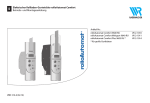
D EN Betriebsanleitung DuoFern Connect Aktor.....................................1 Operating instructions DuoFern Connect actuator..............................25 Artikel-Nr. / Item no.: 3500 08 64 VBD 586-1 (05.13) i Sehr geehrte Kunden, ... D ... mit dem Kauf des DuoFern Connect Aktors haben Sie sich für ein Qualitätsprodukt aus dem Hause RADEMACHER entschieden. Wir danken Ihnen für Ihr Vertrauen. Dieses Produkt ist unter Aspekten des größten Komforts entstanden. Mit einem kompromisslosen Qualitätsanspruch und nach langen Versuchsreihen sind wir stolz, Ihnen dieses innovative Produkt zu präsentieren. Dahinter stehen alle hoch qualifizierten Mitarbeiterinnen und Mitarbeiter aus dem Hause RADEMACHER. i Diese Anleitung... ...beschreibt Ihnen die Montage, den Anschluss und Bedienung des DuoFern Connect Aktors. Bitte lesen Sie diese Anleitung vollständig durch und beachten Sie alle Sicherheitshinweise, bevor Sie mit den Arbeiten beginnen. Bitte bewahren Sie diese Anleitung auf und übergeben Sie die Anleitung bei einem Besitzerwechsel auch dem Nachbesitzer. Bei Schäden, die durch Nichtbeachtung dieser Anleitung und der Sicherheitshinweise entstehen, erlischt die Garantie. Für Folgeschäden, die daraus resultieren, übernehmen wir keine Haftung. 2 i Inhalt D i Sehr geehrte Kunden, ...........................................................................2 i Diese Anleitung.......................................................................................2 1. Zeichenerklärung....................................................................................4 2. Allgemeine Sicherheitshinweise.......................................................5 3. Richtige Verwendung.............................................................................6 4. Falsche Verwendung..............................................................................6 5. Gesamtansicht..........................................................................................7 6. Kurzbeschreibung...................................................................................8 7. Funktionsmerkmale...............................................................................9 8. Beschreibung der einstellbaren Parameter................................ 11 9. Montage / Demontage...................................................................... 14 9.1 Montage...................................................................................... 14 9.2 Demontage................................................................................ 14 10. Elektrischer Anschluss - Sicherheitshinweise............................. 15 10.1 Elektrischer Anschluss............................................................ 16 10.2 Anschlussplan........................................................................... 17 11. An- /Abmelden von DuoFern Sendern........................................ 18 12. An- /Abmelden via Funkcode.......................................................... 19 13. Einstellungen löschen (Reset)......................................................... 20 14. Technische Daten................................................................................. 21 15. CE-Zeichen und EG-Konformität.................................................... 21 16. Zubehör................................................................................................... 22 17. Garantiebedingungen........................................................................ 23 18. SET-Magnet............................................................................................ 23 3 i 1. Zeichenerklärung D Lebensgefahr durch Stromschlag Dieses Zeichen weist Sie auf Gefahren bei Arbeiten an elektrischen Anschlüssen, Bauteilen etc. hin. Es fordert Sicherheitsmaßnahmen zum Schutz von Gesundheit und Leben der betroffenen Person. Hier geht es um Ihre Sicherheit Beachten und befolgen Sie bitte alle so gekennzeichneten Hinweise. HINWEIS/WICHTIG/ACHTUNG Sicherheitshinweise auf weitere, für die einwandfreie Funktion, wichtige Inhalte. Bitte lesen Sie die Bedienungsanleitung des an dieser Stelle beschriebenen externen Gerätes (z. B. eines Rohrmotors). 4 i 2. Allgemeine Sicherheitshinweise D Bei allen Arbeiten an elektrischen Anlagen besteht Lebensgefahr durch Stromschlag. ◆◆ A lle Arbeiten an elektrischen Anlagen dürfen nur durch eine zugelassene Elektrofachkraft erfolgen (s. Kapitel 10. - 10.2). ◆◆ F ühren Sie alle Montage- und Anschlussarbeiten nur im spannungslosen Zustand aus. Der Einsatz defekter Geräte kann zur Gefährdung von Personen und zu Sachschäden führen (Stromschlag, Kurzschluss). ◆◆ Verwenden Sie niemals defekte oder beschädigte Geräte. ◆◆ Prüfen Sie den DuoFern Connect Aktor auf Unversehrtheit. ◆◆ W enden Sie sich bitte an unseren Kundendienst (s. Seite 24), falls Sie Schäden am Aktor feststellen. 5 i 3. Richtige Verwendung D Verwenden Sie den DuoFernConnect Aktor ausschließlich zur Steuerung von: ◆◆ Rollladen- und Sonnenschutzanlagen ◆◆ Jalousien und Raffstore Einsatzbedingungen ◆◆ D er Einbau und der Betrieb eines DuoFern-Funksystems und seiner Komponenten ist nur für solche Anlagen und Geräte zulässig, bei denen eine Funktionsstörung im Sender oder Empfänger keine Gefahr für Personen oder Sachen ergibt oder bei denen dieses Risiko durch andere Sicherheitseinrichtungen abgedeckt wird. ◆◆ F ür den elektrischen Anschluss muss am Einbauort ein 230 V/50 Hz Stromanschluss, mit bauseitiger Freischaltvorrichtung (Sicherung) vorhanden sein. WICHTIG Funkanlagen die auf der gleichen Frequenz senden, können zu Empfangsstörungen führen. i 4. Falsche Verwendung Verwenden Sie das DuoFern Funksystem und seine Komponenten (z. B. den DuoFern Connect Aktor) nie zur Fernsteuerung von Geräten und Anlagen mit erhöhten sicherheitstechnischen Anforderungen oder erhöhter Unfallgefahr. Dies bedarf zusätzlicher Sicherheitseinrichtungen. Beachten Sie die jeweiligen gesetzlichen Regelungen zum Errichten solcher Anlagen. 6 i 5. Gesamtansicht D Antrieb Status-LED Typenschild Sicherungsbügel Befestigungslasche Netzanschluss (230 V / 50 Hz) SET-Magnet Verbinden-Fläche / Trennen-Fläche / HINWEIS An-/Abmelden von DuoFern Sendern s. Seite 18. 7 i 6. Kurzbeschreibung D Mit Hilfe des DuoFern Connect Aktors können Sie Antriebe für Jalousien, Raffstore und Rollläden mit der DuoFern Funktechnologie ergänzen. Der Aktor ist für die Verwendung an Jalousien/Raffstore optimiert. Er kann auf Wunsch in unterschiedlichen Anwendungsszenarien die Lamellen der Jalousie / des Raffstores automatisch wenden. Zudem ist ein Kurzzeit-Befehl (Tipp-Betrieb) integriert mit dem die Lamellen per Handsender komfortabel den persönlichen Wünschen entsprechend justiert werden können. Sobald Sie den DuoFern Connect Aktor in ein DuoFern Funknetzwerk integrieren, können Sie viele Funktionen der entsprechenden DuoFern Steuergeräte für den angeschlossenen Antrieb nutzen. DuoFern Aktoren und -Sender müssen mit dem DuoFernNetzwerk verbunden werden. Um die Funktionen der entsprechenden DuoFern Steuergeräte (z. B. DuoFern Handsender Standard) nutzen zu können, müssen Sie den DuoFern Connect Aktor mit dem DuoFern Netzwerk verbinden. Verwenden Sie den beiliegenden SET-Magneten um den Aktor in den Verbinden- bzw. Trennen-Modus zu schalten (s. Seite 18). HINWEIS Eine ausführliche Beschreibungen der unterschiedlichen Funktionen, Einstellmöglichkeiten und möglichen Kombinationen zum DuoFern System erhalten Sie unter: http://www.rademacher.de/duofern. 8 i 7. Funktionsmerkmale D DuoFern HomePilot® DuoFern Umweltsensor DuoFern Handzentrale * WR ConfigTool mit DuoFern Handzentrale RolloTron Comfort DuoFern / Troll Comfort DuoFern DuoFern Handsender Standard DuoFern Wandtaster Funktion Wertebereich Auf / Stopp / Ab Werkseinstellung - 2. Direktes Anfahren einer %-Position 0 % - 100 % - 3. Manuellbetrieb ein / aus 4. Zeitautomatik ein / aus 5. Zufallsfunktion 6. Morgendämmerungsfunktion 7. Morgendämmerungsautomatik ein / aus 8. Abenddämmerungsfunktion 9. Abenddämmerungsautomatik ein / aus 10. Sonnenfunktion 11. Sonnenautomatik ein / aus 12. Sonnenposition 13. Windfunktion 14. Windautomatik ein / aus 15. Drehrichtung Wind 16. Regenfunktion 17. Regenautomatik ein / aus 18. Drehrichtung Regen 19. Laufzeit 20. Lüftungspositionsfunktion ein / aus 21. Lüftungsposition 22. Drehrichtungsumkehr 23. Verbindungstest 24. Verbinden mit Funkcode ein / aus ein / aus ein / aus ein / aus ein / aus 0 % -100 % ein / aus Auf / Ab ein / aus Auf / Ab 2 s – 150 s ein / aus 1 % - 99 % ein / aus - aus ein aus aus aus 50 % aus Auf aus Auf 150 s aus 80 % aus - 1. Manuelle Bedienung ● ● ● ● ● ● ● ● ● ● ● ● ● ● ● ● ● ● ● ● ● ● ● ● ● ● ● ● ● ● ● ● ● ● ● ● ● ● ● ● ● ● ● ● ● ● ● ● ● ● ● ● ● ● ● ● ● ● ● ● ● ● ● ● ● ● ● ● ● 9 i 7. Funktionsmerkmale D DuoFern HomePilot ® DuoFern Umweltsensor DuoFern Handzentrale * WR ConfigTool mit DuoFern Handzentrale RolloTron Comfort DuoFern / Troll Comfort DuoFern DuoFern Handsender Standard DuoFern Wandtaster Funktion 25. Reset über Funk (3-Stufig) 26. Einknopf-Bedienung 27. Tipp-Betrieb 28. Jalousiemodus 29. Standard-Lamellenposition ** 30. Autom. Wenden nach manuellem Stopp Richtung "Ab" ** 31. Autom. Wenden in Sonnenposition ** 32. Autom. Wenden in Lüftungsposition ** 33. Autom. Wenden nach Anfahren einer %-Position ** 34. Lamellenlaufzeit ** 35. Motor Reaktionszeit Wertebereich - Werkseinstellung - ein / aus 0-100% aus 0% ein / aus ● ● ● ● ● ● ● ● ein ● ● ein / aus ein / aus aus aus ● ● ● ● ein / aus ein ● ● 100 ms - 5000 ms 0 ms / 160 ms / 480 ms 900 ms 0 ms (aus) ● ● ● ● * Die Software „WR ConfigTool“ können Sie von unserer Internetseite www.rademacher.de herunterladen. ** Steht nur zur Verfügung wenn „Jalousiemodus“ eingeschaltet ist. 10 ● i 8. Beschreibung der einstellbaren Parameter D Zur Basis-Konfiguration (Installation) des Aktors sind hier die wesentlichen, einstellbaren Parameter beschrieben. Laufzeit: Hier wird die Zeit eingestellt, die der Antrieb für einen vollständigen Hub des Behangs benötigt. Um diese Zeit zu erfassen, fahren Sie den Behang in die untere Endlage und fahren ihn in die obere Endlage. Erfassen Sie während des Hubs die Zeit möglichst exakt. Um Schwankungen der Laufgeschwindigkeit bei wechselnden Temperaturen zu berücksichtigen, schlagen Sie ca. 1-2 Sekunden auf die gemessene Zeit auf. Die Einstellung der Laufzeit ist erforderlich, um ein gezieltes Anfahren einer bestimmten Position (z.B. mit HomePilot) zu ermöglichen. Je genauer die Zeit erfasst und eingestellt wird, je exakter können gewünschte Zwischenposition (z.B. die Sonnenposition) angefahren werden. Jalousiemodus: Ist dieser Modus aktiv, stehen die automatischen Wendefunktionen zur Verfügung. Bei Rollläden und Markisen sollte dieser Modus abgeschaltet sein. Standard-Lamellenposition: Mit diesem Parameter wird die Position eingestellt, in der die Lamellen nach dem automatischen Wenden stehen (0% = offen (Richtung „Auf“ gedreht), 100% = geschlossen (Richtung „Ab“ gedreht). Automatisches Wenden nach manuellem Stopp Richtung „Ab“: Ist dieser Parameter aktiviert, werden die Lamellen bei jedem manuellem Stopp in Richtung „Ab“ automatisch gewendet und in die eingestellte Standard-Lamellenposition gefahren. 11 i 8. Beschreibung der einstellbaren Parameter D Automatisches Wenden in Sonnen- bzw. Lüftungsposition: Wird der jeweilige Parameter aktiviert, werden die Lamellen nach dem Anfahren der Sonnen- bzw. Lüftungsposition automatisch gewendet und in die eingestellte Standard-Lamellenposition gefahren. Diese Funktion kann für das Anfahren der Sonnen- bzw. Lüftungsposition getrennt eingestellt werden. Automatisches Wenden nach Anfahren einer %-Position: Ist dieser Parameter aktiviert, werden die Lamellen nach dem Anfahren einer bestimmten %-Position (z. B. mit HomePilot) automatisch gewendet und in die eingestellte Standard-Lamellenposition gefahren. Lamellenlaufzeit: Die Laufzeit einer vollständigen Lammellenbewegung muss erfasst und eingestellt werden. Dieses ist erforderlich, um aus jeder Position heraus die gewünschte Lamellenposition korrekt anfahren zu können. Zum Erfassen dieser Position fahren Sie (bei abgeschaltetem Jalousiemodus) die Jalousie / den Raffstore in eine mittlere Position. Dann starten Sie den Motor Richtung „Auf“ und erfassen die Zeit, bis sich der Behang zu heben beginnt. Der mögliche Einstellbereich ist 100 ms - 5000 ms (0,1 s - 5 s). 12 i 8. Beschreibung der einstellbaren Parameter D Motor Reaktionszeit (Totzeit) Hier können Sie die Reaktionszeit einstellen, die der Motor nach dem Einschalten benötigt um anzufahren. Beachten Sie dazu den Motortyp und die Angaben der jeweiligen Motorhersteller. Bei Motoren mit mechanischer Endpunkteinstellung ist die Reaktionszeit sehr kurz – in diesem Fall ist die Einstellung „Aus“ (0 ms) empfohlen. Bei Motoren mit elektronischer Endpunkteinstellung (sogenannte „elektronische Motoren“) kann die Reaktionszeit des Motors einen erheblichen Einfluss auf die Genauigkeit beim Anfahren einer bestimmten Lamellenposition haben. Wird ein „elektronischer Motor“ verwendet, sollte die Reaktionszeit durch Versuche oder beim Motor-Hersteller ermittelt werden. Bei elektronischen Motoren wird die Einstellung „160 ms“ empfohlen, bei einigen elektronischen Motoren ist evtl. die Einstellung „480 ms“ erforderlich. Sollten exakte Angaben zur Reaktionszeit des Motors zur Verfügung stehen, kann diese ebenfalls eingestellt werden (individuelle Reaktionszeit). 13 i 9. Montage / Demontage D Der DuoFern Connect Aktor ist zur Aufputzmontage vorgesehen. ACHTUNG Um einen optimalen Betrieb zu gewährleisten, sollten Sie den DuoFern Connect Aktor nicht auf einem metallischen Untergrund oder in der Nähe von metallischen Gegenständen montieren. i 9.1 Montage 1. Das Netz spannungslos schalten. 2. Den DuoFern Connect Aktor gemäß Kapitel 10. - 10.2 anschließen. 3. Den DuoFern Connect Aktor montieren. 4. Netzspannung wieder einschalten. 5. Den DuoFern Connect Aktor im DuoFern Funknetzwerk anmelden, s. Kapitel 11. i 9.2 Demontage 1. Den DuoFern Connect Aktor aus dem DuoFern Funknetzwerk abmelden, s. Kapitel 11. 2. Das Netz spannungslos schalten. 3. Den DuoFern Connect Aktor abklemmen und demontieren. 4. Die Anlage wieder betriebsbereit machen und das Netz wieder einschalten. 14 i 10. Elektrischer Anschluss - Sicherheitshinweise D Es besteht Lebensgefahr durch Stromschlag. Der elektrische Anschluss und alle Arbeiten an elektrischen Anlagen müssen durch eine zugelassene Elektrofachkraft nach den Anschlusshinweisen in dieser Anleitung erfolgen. ◆◆ F ühren Sie alle Montage- und Anschlussarbeiten nur im spannungslosen Zustand aus. ◆◆ T rennen Sie die Zuleitung allpolig vom Netz und sichern Sie sie gegen Wiedereinschalten. ◆◆ Prüfen Sie die Anlage auf Spannungsfreiheit. ◆◆ V ergleichen Sie vor dem Anschluss die Angaben zu Spannung/ Frequenz auf dem Typenschild mit denen des örtlichen Netzbetreibers. ◆◆ Falsche Verdrahtung kann zum Kurzschluss und zur Zerstörung des Gerätes führen. ◆◆ Beachten Sie die Reihenfolge der Anschlussbelegung im Anschlussplan auf Seite 17 und auf dem Typenschild. 15 i 10.1 Elektrischer Anschluss D 1. Schalten Sie die Netzspannung aus und sichern Sie sie gegen Wiedereinschalten. 2. Schließen Sie die Adern gemäß den Angaben auf dem Typenschild und gemäß dem Anschlussplan auf Seite 17 an. Das unbeabsichtigte Herausziehen der Anschlusskabel während des Betriebs kann zu lebensgefährlichen Situationen durch Stromschlag oder Kurzschluss führen. Sichern Sie beide Anschlusskabel mit Hilfe der Zugentlastungen gegen Herausziehen. 3. Verbinden Sie Stecker und Kupplung der beiden Anschlussleitungen mit dem DuoFern Connect Aktor. 4. Schalten Sie die Netzspannung wieder ein und prüfen Sie die Anlage auf die richtige Funktion. Das Herausziehen des Steckers oder der Kupplung während des Betriebs, kann eventuell zur Zerstörung des Antriebs oder des DuoFern Connect Aktors führen. Sichern Sie den Stecker und die Kupplung unbedingt durch Herunterdrücken des jeweiligen Sicherungsbügels. Die Sicherungsbügel müssen vollständig einrasten. 16 10.2 Anschlussplan D 3 L2 IN N 1 2 1 Art.-Nr. : OUT N DuoFern 3 Netz 230 V / 50 Hz) 230V / 50 Hz 434,5 MHz Standby < 0,5 W IP 54 5 (2) A µ Antrieb Antrieb 3 = ▼ (schwarz / braun) PE = (grün / gelb) 2 = ▲ (braun) 1 = N (blau) Netz (230 V / 50 Hz) 3 L2 IN N 1 Art.-Nr. : 230V / 50 Hz 434,5 MHz Standby < 0,5 W IP 54 5 (2) A µ 2 1 DuoFern 3 2 = L1 (schwarz) OUT N i PE = (grün / gelb) 1 = N (blau) 17 i 11. An- /Abmelden von DuoFern Sendern D Damit Sie den DuoFern Connect Aktor mit einem DuoFern Sender steuern können, müssen Sie jeden gewünschten DuoFern Sender am Aktor anmelden. Sie können max. 20 DuoFern Sender (z. B. DuoFern Handsender Standard) am Aktor anmelden. Weitere Hinweise zur Anmeldung finden Sie in einer „Anmeldematrix“ auf unserer Internetseite unter: www.rademacher.de 1. Halten Sie den beiliegenden SET-Magneten (s. Seite 23) an dieVerbinden (Anmelden) - oder Trennen (Abmelden) - Fläche des Aktors. 2. Die Status LED blinkt grün, der Antrieb fährt kurz an und ein entsprechendes Signal wird aus- gesendet. HINWEIS: Der An- / Abmeldemodus bleibt 60 Sekunden aktiv. 3. Den gewünschten Duo- Fern Sender in den Ver- binden-Modus (Anmelden) bzw. Trennen-Mo- dus (Abmelden) schal- ten (lesen Sie dazu die jeweilige Bedienungsanleitung). Verbinden (Anmelden) SET-Magnet Trennen (Anmelden) SET-Magnet SET-Magnet (s. Seite 23) 18 i 11. An- /Abmelden von DuoFern Sendern D 4. Nach erfolgreicher An- / Abmeldung leuchtet die Status-LED konstant grün und der Antrieb fährt zur Bestätigung kurz an. 5. Den nächsten DuoFern Sender an- / abmelden, dazu 1. bis 3. wiederholen oder die An- /Abmeldung beenden. HINWEIS Die Status-LED leuchtet rot, wenn die An-/Abmeldung fehlschlug, zum Beispiel wenn: ◆◆ bereits 20 DuoFern Sender angemeldet sind. ◆◆ v ersucht wird ein ungeeignetes Gerät (z. B. einen anderen DuoFern Aktor) anzumelden. ◆◆ v ersucht wird einen DuoFern Sender abzumelden, der gar nicht angemeldet ist. i 12. An- /Abmelden via Funkcode Mit Hilfe des Funkcodes können Sie den DuoFern Connect Aktor direkt ansteuern, um zum Beispiel auch nach der Installation weitere DuoFern-Sender am Aktor anzumelden. Der Funkcode ist ab Werk mit einem Etikett und auf dem Aktor aufgeklebt. HINWEIS Zur Nutzung des Funkcodes ist ein entsprechender Sender z.B. eine DuoFern Handzentrale (Art.-Nr. 3481 00 60) oder ein HomePilot (Art.-Nr. 3400 08 19) erforderlich. Eine detaillierte Beschreibung zur An- und Abmeldung via Funkcode finden Sie in der jeweiligen Bedienungsanleitung der beiden Geräte. Der Funkcode ist 120 Minuten nach Einschalten der Netzspannung aktiv. Gegebenenfalls muss die Stromzufuhr kurz unterbrochen werden, um den Funkcode zu nutzen. 19 i 13. Einstellungen löschen (Reset) D 1. Halten Sie den beiliegenden SET-Magneten solange auf die „Trennen“-Fläche, bis die Status-LED konstant rot leuchtet. 2. Alle Einstellungen werden gelöscht und auf die Werkseinstellungen zurückgesetzt. 3. Alle angemeldeten DuoFern Sender werden automatisch abge- meldet. 4. Danach befindet sich der DuoFern Connect Aktor wieder im Auslieferungszustand. 20 i 14. Technische Daten D Versorgungsspannung: 230 V / 50 Hz Stand-by Leistung: < 0,5 W Schaltleistung: max. 5 A ohmsche Last max. 2 A induktive Last Ausgang: 1 x Rohrmotor Reichweite: - im Gebäude: ca. 30 m (je nach Bausubstanz) - im Freien: ca. 100 m Sendefrequenz: 434,5 MHz Maximale Anzahl: - DuoFern Sender: 20 Zulässige Umgebungstemperatur: - 25 °C bis + 55°C i Schutzart: IP54 Maße: 123,5 x 33,5 x 26,5 mm (L x B x H) 15. CE-Zeichen und EG-Konformität Das vorliegende Produkt erfüllt die Anforderungen der geltenden europäischen und nationalen Richtlinien. 1999/5/EG R&TTE Richtlinie Die Konformität wurde nachgewiesen. Die entsprechenden Erklärungen und Unterlagen sind beim Hersteller hinterlegt. RADEMACHER Geräte-Elektronik GmbH&Co. KG Buschkamp 7 46414 Rhede 21 i 16. Zubehör D Steckverbindung (IP54, max 16 A) STAK3 N STASI 3 Farbe Art.-Nr. Kupplung STAK3 N: (schwarz) 7000 00 83 Stecker STAS3 N, inkl. Sicherungsbügel (schwarz) 7000 00 84 - - - 7000 00 85 Sicherungsbügel STASI 3 22 STAS3 N i 17. Garantiebedingungen D RADEMACHER Geräte-Elektronik GmbH & Co. KG gibt eine 24 monatige Garantie für Neugeräte, die entsprechend der Einbauanleitung montiert wurden. Von der Garantie abgedeckt sind alle Konstruktionsfehler, Materialfehler und Fabrikationsfehler. Ausgenommen von der Garantie sind: ◆◆ ◆◆ ◆◆ ◆◆ ◆◆ F ehlerhafter Einbau oder Installation Nichtbeachtung der Einbau- und Bedienungsanleitung Unsachgemäße Bedienung oder Beanspruchung Äußere Einwirkungen wie Stöße, Schläge oder Witterung Reparaturen und Abänderungen von dritten, nicht autorisierten Stellen ◆◆ Verwendung ungeeigneter Zubehörteile ◆◆ Schäden durch unzulässige Überspannungen ( z. B. Blitzeinschlag) ◆◆ Funktionsstörungen durch Funkfrequenzüberlagerungen und sonstige Funkstörungen Innerhalb der Garantiezeit auftretende Mängel beseitigt RADEMACHER kostenlos entweder durch Reparatur oder durch Ersatz der betreffenden Teile oder durch Lieferung eines gleichwertigen oder neuen Ersatzgerätes. Durch Ersatzlieferung oder Reparatur aus Garantiegründen tritt keine generelle Verlängerung der ursprünglichen Garantiezeit ein. i 18. SET-Magnet (s. Seite 47) 23 RADEMACHER Geräte-Elektronik GmbH & Co. KG Buschkamp 7 46414 Rhede (Deutschland) [email protected] www.rademacher.de Service: Hotline 01807 933-171* Telefax +49 2872 933-253 [email protected] * 30 Sekunden kostenlos, danach 14 ct/Minute aus dem dt. Festnetz bzw. max. 42 ct/Minute aus dem dt. Mobilfunknetz. 24 D Technische Änderungen, Druckfehler und Irrtümer vorbehalten. Abbildungen unverbindlich. i D EN Betriebsanleitung DuoFern Connect Aktor.....................................1 Operating instructions DuoFern Connect actuator..............................25 Item no. 3500 08 64 VBD 586-1 (05.13) i Dear Customers... EN ...with your purchase of this DuoFern Connect actuator, you have decided for a quality product manufactured by RADEMACHER. We would like to thank you for your confidence. This product has been designed in an effort to the greatest possible ease of operation. With uncompromising quality requirements, after extensive test series, we are proud to present this innovative product to you. All of our highly qualified staff at RADEMACHER stand behind this product. i These instructions... …describe how to install, connect and operate the DuoFern Connect actuator. Before you begin work, please read these instructions all the way through and follow all of the safety instructions. Please save these instructions and give them to any future owners. For damage resulting from noncompliance with these instructions and safety instructions, the guarantee is void. We assume no liability for any consequent damage. 26 i Contents EN i Dear Customers.................................................................................... 26 i These instructions................................................................................ 26 1. Key to Symbols...................................................................................... 28 2. General safety instructions............................................................... 29 3. Correct usage......................................................................................... 30 4. Incorrect use.......................................................................................... 30 5. General view.......................................................................................... 31 6. Brief description................................................................................... 32 7. Functional characteristics................................................................. 33 8. Description of the configurable parameters.............................. 35 9. Installation / Dismantling.................................................................. 38 9.1 Installation.................................................................................. 38 9.2 Dismantling................................................................................ 38 10. Electrical connection - Safety instructions.................................. 39 10.1 Electrical connection.............................................................. 40 10.2 Wiring diagram......................................................................... 41 11. Logging DuoFern transmitters on/off.......................................... 42 12. Logging on and off per radio code................................................ 43 13. Erase data (reset).................................................................................. 44 14. Technical data........................................................................................ 45 15. CE mark and EC conformity.............................................................. 45 16. Accessories............................................................................................. 46 17. Warranty conditions............................................................................ 47 18. SET Magnet............................................................................................. 47 27 i 1. Key to Symbols EN Danger of fatal electric shock. This sign warns of danger when working on electrical connections, components etc. It requires that safety precautions be taken to protect the health and life of the person concerned. This concerns your safety. Please pay particular attention to and carefully follow all instructions with this symbol. NOTE/IMPORTANT/ATTENTION This is to draw your attention to information which works is important to ensure trouble-free operation. Please read the operating instructions for an external device described at this point, (e. g. a tubular motor). 28 i 2. General safety instructions EN All work performed on electrical equipment is associated with a risk of electric shock and electrocution. ◆◆ T he electrical connection and all work on electrical systems must only be carried out by a qualified electrician (see chapter 10. - 10.2). ◆◆ C arry out all installation and connection work only in an isolated, deenergised state. The use of defective equipment can lead to personal injury and damage to property (electric shocks, short circuiting). ◆◆ Never use defective or damaged equipment. ◆◆ Check that the DuoFern Connect actuator is intact. ◆◆ P lease contact our Customer Service department (see page 48) in the event of faults or damage to the actuator. 29 i 3. Correct usage EN Only use the DuoFern Connect actuator for the control of: ◆◆ Roller shutters and Sun shading systems ◆◆ Blinds and external Venetian blinds Operating conditions ◆◆ The installation and operation of the DuoFern radio system and its components is only permitted for those systems and devices where a malfunction in the transmitter or receiver would not cause a danger to persons or property or where this risk is already covered by other safety equipment. ◆◆ F or the electrical connection a 230 V / 50 Hz power supply, together with a site-provided isolating device (fuse), must be available at the installation site. IMPORTANT Radio systems which transmit on the same frequency can cause interference. i 4. Incorrect use Never use the DuoFern radio system and its components (e. g. DuoFern Connect actuator) for remote control of devices and systems with heightened safety-relevant requirements or a heightened risk of accident. Such use would require additional safety equipment. Observe the respective statutory regulations for the installation of such systems. 30 i 5. General view EN Drive Status LED Type plate Safety clip Fastening lug Mains (230 V / 50 Hz) SET Magnet Connect surface / Disconnect surface / NOTE Log on/off to/from DuoFern transmitters, s. page 42. 31 i 6. Brief description EN The DuoFern Connect actuator can be used to equip drives for blinds, external Venetian blinds and roller shutters with DuoFern radio technology. As soon as you integrate your DuoFern Connect actuator into a DuoFern radio network, you can make use of many functions offered by the corresponding DuoFern controllers in combination with the connected drive. The DuoFern actuators and transmitters must be connected to the DuoFern network. In order to make use of the corresponding controllers (e.g. DuoFern manual transmitter Standard), you must first connect the DuoFern Connect actuator with the DuoFern network. Use the enclosed SET magnet to switch the actuator to connect and disconnect mode (see page 42). NOTE A detailed description of the various functions, settings and possible combinations for DuoFern systems can be obtained under: http://www.rademacher.de/duofern. 32 i 7. Functional characteristics EN DuoFern HomePilot DuoFern environmental sensor DuoFern manual central operating unit * WR ConfigTool with DuoFern manual central operating unit RolloTron Comfort DuoFern / Troll Comfort DuoFern DuoFern Standard manual transmitter DuoFern Wall controller Function Valuerange Up / Stop / Down Factorysetting - 2. Direct drive to a %-Position 0 % - 100 % - 3. Manual operation on / off 4. Timer on / off 5. Random function 6. Automatic dawn function 7. Automatic dawn function on / off 8. Automatic dusk function 9. Automatic dusk function on / off 10. Solar program 11. Automatic solar function on / off 12. Sun position 13. Wind program 14. Automatic wind function on / off 15. Direction of rotation for wind 16. Rain program 17. Automatic rain function on / off 18. Direction of rotation for rain 19. Runtime 20. Ventilationposition function on / off 21. Ventilationposition 22. Direction reversal 23. Connection test 24. Connecting via radio code on / off on / off on / off on / off on / off 0 % -100 % on / off Up / Down on / off Up / Down 2 s – 150 s on / off 1 % - 99 % on / off - off on off off off 50 % off Up off Up 150 s off 80 % off - 1. Manual control ● ● ● ● ● ● ● ● ● ● ● ● ● ● ● ● ● ● ● ● ● ● ● ● ● ● ● ● ● ● ● ● ● ● ● ● ● ● ● ● ● ● ● ● ● ● ● ● ● ● ● ● ● ● ● ● ● ● ● ● ● ● ● ● ● ● ● ● ● 33 i 7. Functional characteristics EN DuoFern HomePilot DuoFern environmental sensor DuoFern manual central operating unit * WR ConfigTool with DuoFern manual central operating unit RolloTron Comfort DuoFern / Troll Comfort DuoFern DuoFern Standard manual transmitter DuoFern Wall controller Function 25. Reset via radio (3-stage) 26. Single-button operation 27. Jog-Mode 28. Blinds mode 29. Standard slat position ** 30. Auto tilt after manual Stop direction "Down" ** 31. Auto tilt to Sun position ** 32. Auto tilt to ventilation position ** 33. Auto tilt after moving to a %-Position ** 34. Slat run time ** 35. Motor reaction time * Valuerange - Factorysetting - on / off 0-100% off 0% on / off ● ● ● ● ● ● ● ● on ● ● on / off on / off off off ● ● ● ● on / off on ● ● 100 ms - 5000 ms 0 ms / 160 ms / 480 ms 900 ms 0 ms (off) ● ● ● ● The „WR ConfigTool“ software can be downloaded from our website at www.rademacher.de ** Not available if „blinds mode“ is activated. 34 ● i 8. Description of the configurable parameters EN The most important configurable parameters are described here for carrying out the basic configuration (installation) of the actuator. Running time: This sets the time which the drive requires for a complete lift of the shutters. In order to record the time, please move the shutters down to the lower limit position and then move them to the upper limit position. Record the time as precisely as possible during the lifting process. Add 1 to 2 seconds to the measured duration in order to allow for deviations in the running time caused by temperature changes. Configuration of the running time is required to enable targeted movement to a specified position (e.g. using the HomePilot). The more precisely the time is recorded, the more accurately the desired intermediate position (e.g. sun position) will be assumed. Blinds mode: If this mode is active, the automatic slat tilting functions are available. This mode should be deactivated for use with roller shutters and awnings. Standard slat position *** This parameter sets the position in which the slats are to be turned after automatic tilting (0% = open (tilted in the „up“ position), 100% = closed (tilted in the „down“ position). Automatic tilt after manual stop direction „Down“: If this parameter is activated, the slats will be automatically tilted to the „down“ position after manually stopping and will be shifted to the default slat position. 35 i 8. Description of the configurable parameters EN Automatic tilting in sun and ventilation positions: If the respective parameter is activated, the slats will be automatically tilted after moving to the corresponding sun or ventilation position and will be shifted to the default slat position. This function can be configured separately for the corresponding sun and ventilation position. Automatic tilt after moving to a %-position: If this parameter is activated, the slats will be tilted automatically and shifted to the default slat position after moving to a specific %-position (e.g. with the HomePilot). Slat run time: The run time must be recorded and configured for a complete slat movement. This is necessary in order to be able to correctly move to a desired slat position from any other position. In order to record this position, move the blinds / external Venetian blinds to the central position (with blinds mode switched off ). Then start the motor in the “up” position and record the time required until the shutter starts to lift. The possible adjustment range is 100 ms - 5000 ms (0.1 s - 5 s). 36 i 8. Description of the configurable parameter EN Motor reaction time (dead time) Here you can set the time required by the motor after switching on before it starts up. In order to do so, observe the motor type and specifications given by the respective motor manufacturer. For motors with mechanical end point settings, the reaction time is extremely short – in this case the “off” setting (0 ms) is recommended. For motors with electronic end point setting (so called “electronic motors”), the reaction time of the motor can have a significant influence on its accuracy when moving to specific slat positions. If an “electronic motor” is used, the reaction time should be ascertained by trial and error or by the motor manufacturer. For electronic motors, a setting of “160 ms” is recommended, however, some electronic motors may require a setting of “480 ms”. If precise reaction times are available for the motor, then this can be custom set (individual reaction time). 37 i 9. Installation / Dismantling EN The DuoFern Connect actuator is intended for surface-mounting. ATTENTION In order to ensure optimal operation, the DuoFern Connect actuator should not be installed on a metallic base or near metal objects. i 9.1 Installation 1. Switch off the mains. 2. Connect DuoFern Connect actuator in accordance with chapter 10. - 10.2. 3. Mount the DuoFern Connect actuator. 4. Reconnect the mains power. 5. Register the DuoFern Connect actuator in the DuoFern radio network, see chapter 11. i 9.2 Dismantling 1. Log off the DuoFern Connect actuator from the DuoFern radio network, see chapter 11. 2. Switch off the mains. 3. Disconnect and demount the DuoFern Connect actuator. 4. Prepare the system for operation and switch the power back on. 38 i 10. Electrical connection - Safety instructions EN There is a risk of fatal electric shocks. ◆◆ The electrical connection and all work on electrical systems must only be carried out by a qualified electrician in accordance with the connection instructions in these operating instructions. ◆◆ Carry out all installation and connection work only in an isolated, deenergised state. ◆◆ Disconnect all phases of the mains power supply cable and secure it to prevent re-connection. ◆◆ Check that the system is dead. ◆◆ Prior to connecting, compare the information about voltage/ frequency on the device with those of the local electrical grid operator. ◆◆ Incorrect wiring may lead to short-circuits and destruction of the device. ◆◆ Observe the sequence of connector pin assignments in the wiring diagram on page 41 and on the type plate. 39 i 10.1 Electrical connection EN 1. Switch off the mains power and secure it to prevent any reactivation. 2. Connect the wires in accordance with the specifications given on the type plate and in accordance with the wiring diagram on page 41. Unintentional removal of the connecting cable during operation of the equipment can lead to life-threatening situations due to electric shocks or short circuits. Secure both connecting cables against removal with the help of the tension relief mechanism. 3. Connect the plug and coupling for both connecting leads with the DuoFern Connect actuator. 4. Switch the mains power back on and check that the system is working correctly. Removing the plug or coupling during operation of the equipment can damage the drive or the DuoFern radio Connect actuator. Always secure the plug and coupling by engaging the corresponding safety clip. The safety clips must fully engage. 40 10.2 Wiring diagram EN 3 L2 IN N 1 2 1 Art.-Nr. : OUT N DuoFern 3 Mains 230 V / 50 Hz) 230V / 50 Hz 434,5 MHz Standby < 0,5 W IP 54 5 (2) A µ Drive Drive 3 = ▼ (black / brown) PE = (green / yellow) 2 = ▲ (brown) 1 = N (blue) Mains (230 V / 50 Hz) 3 L2 IN N 1 Art.-Nr. : DuoFern 1 230V / 50 Hz 434,5 MHz Standby < 0,5 W IP 54 5 (2) A µ 2 3 2 = L1 (black) OUT N i PE = (green / yellow) 1 = N (blue) 41 i 11. Logging DuoFern transmitters on/off EN You must assign every required DuoFern transmitter to the DuoFern Connect actuator in order that the actuator can be controlled with a DuoFern transmitter. You can assign max. 20 DuoFern transmitters (e. g. RolloTron Pro Comfort DuoFern) to the actuator. Additional informations about logging on can be obtained from the log-on matrix on our website under www.rademacher.de. 1. Use the supplied SET magnets (see page 47) to touch either the“Connect (log-on)” or “Disconnect (log-off )” areas on the actuator. 2. The status LED flashes green, the drive starts up briefly and a corresponding signal is given. NOTE: Log-on/off mode remains active for 60 seconds. Connect (log-on) SET Magnet Disconnect (log-off) 3. Switch the desired Duo Fern transmitter to “Con- nect” mode (log-on) or “Disconnect” mode (logoff) - (please refer to the corresponding opera- ting instructions). SET Magnet SET Magnet (see page 47) 42 i 11. Logging DuoFern transmitters on/off EN 4. If log-on/log-off is successful, the status LED will light up green and the drive starts up briefly by way of confirmation. 5. Register the next DuoFern transmitter. In order to do so, repeat steps 1 to 3, or else terminate registration. NOTE The status LED lights up red if the registration process fails, for example if: ◆◆ 20 DuoFern transmitters have already been registered. ◆◆ an attempt is made to register an unsuitable device (e. g. other DuoFern actuator). ◆◆ a n attempt is made to log-off a DuoFern transmitter that is not logged-on. i 12. Logging on and off per radio code You can control the DuoFern Connect actuator directly using the radio code in order, for example, to be able to connect further DuoFern transmitters to the actuator after installation. The radio code is provided from factory in the form of a label attached to the actuator. NOTE A corresponding transmitter is required (e.g. DuoFern manual central operating unit, item no. 3481 00 60 or HomePilot, item no. 3400 08 19) in order to use the radio code. A more detailed description of the login/log-off process via the radio code can be found in the respective operating instructions for both devices. The radio code is only active for 120 minutes after switching on the power supply. For this reason, it may be necessary to briefly interrupt the power supply, in order to be able to use the radio code. 43 i 13. Erase data (reset) EN 1. Hold the SET magnets provided against the “Disconnect” surface until the status LED lights up continuously red. 2. All settings will be erased and reset to the default factory setting. 3. All of the registered DuoFern transmitters are automatically logged-off. 4. Subsequently, the DuoFern Connect actuator will be reset to its original supplied state. 44 i 14. Technical data EN Supply voltage: 230 V / 50 Hz Standby consumption: < 0,5 W Switching load: max. 5 A ohmic load max. 2 A inductive load Output: 1 x tubular motor Range: - in a building: approx. 30 m (depending on contruction) - outside: approx. 100 m i Transmission frequency: 434,5 MHz Maximum number: - DuoFern transmitters: 20 Permissible ambient temperature: - 25 °C to + 55°C Protection type: IP54 Dimensions: 123,5 x 33,5 x 26,5 mm (L x W x H) 15. CE Mark and EC Conformity The present product complies with the requirements of the current European and national directives. 1999/5/EC R&TTE directive Conformity has been verified. The corresponding declarations and documentation are available on file at the manufacturer’s premises. RADEMACHER Geräte-Elektronik GmbH&Co. KG Buschkamp 7 46414 Rhede 45 i 16. Accessories EN Plug-ans socket connections (IP54, max 16 A) STAK3 N STASI 3 colour item no. Coupling STAK3 N: (black) 7000 00 83 Plug STAS3 N, incl. safety clip (black) 7000 00 84 - - - 7000 00 85 Safety clip STASI 3 46 STAS3 N i 17. Warranty conditions EN RADEMACHER Geräte-Elektronik GmbH provides a 24-month warranty for new systems that have been installed in compliance with the installation instructions. All construction faults, material defects and manufacturing defects are covered by the warranty. The following are not covered by the warranty: ◆◆ ◆◆ ◆◆ ◆◆ ◆◆ ◆◆ ◆◆ ◆◆ Incorrect fitting or installation Non-observance of the installation and operating instructions Improper operation or wear and tear External influences, such as impacts, knocks or weathering Repairs and modifications by third party, unauthorised persons Use of unsuitable accessories Damage caused by unacceptable excess voltage (e. g. lightning) Operational malfunctions caused by radio frequency overlaps and other such radio interference RADEMACHER shall remedy any defects, which occur within the warranty period free of charge either by repair or by replacement of the affected parts or by supply of a new replacement unit or one to the same value. There is no general extension of the original warranty period by delivery of a replacement or by repair as per the terms of the warranty. i 18. SET Magnet Magnet 47 RADEMACHER Geräte-Elektronik GmbH & Co. KG Buschkamp 7 46414 Rhede (Germany) [email protected] www.rademacher.de Service: Hotline 01807 933-171* Telefax +49 2872 933-253 [email protected] * 30 seconds free of charge, subsequently 14 cents / minute from German fixed line networks and max. 42 cents / minute from German cellular networks. Subject to technical modifications, misprints and errors excepted. Figures subject to change. i