1
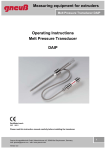
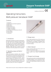
Operating Instructions
Pressure Transducer Testing Unit
Version 3
Melt pressure transducers are often operated under very rough production conditions. This
may lead to the transducer being mechanically damaged, however, this does not
necessarily lead to the measuring accuracy being impaired. The correct function of the
transducers can be tested with the pressure transducer testing unit.
Scope of supply:
1.
Suitcase with foamed intermediate layer.
2.
Hydraulic pressure transducer testing unit with digital pressure gauge (high-precision measurement
of 0-1000 bar) with turnstile.
3.
2 indicator plugs G 1/2-a.
4.
2 adaptors G 1/2-a to 1/2"-20 UNF and 2 adaptors G 1/2-a to 18 x 1,5.
5.
1 roll of caulking strip.
6.
1 screw driver for levelling the digital pressure gauge.
7.
Acceptance Certificate 3.1B
Technical Data:
Pump
Pressure gauge
Pressure 1st cylinder
: 250 bar
Maximum pressure
: 1300 bar
Filling medium
: Univis J13
Generation of pressure : turnstile
reversible
Fine setting
: lateral hand wheel
Connections
: 3 x G1/2-a
2 x adaptors
1/2" 20-UNF and M18x1,5
Dimensions LxWxH
: 290x190x110 mm
Weight
: approx. 8 kg
Measuring range
Pressure 2nd cylinder
Overload safety
Overload display
Display
: 0 - 1000 bar
: 1000 bar
: Double nominal pressure
: flashing LCD-display
: 3 1/2 figure LCD-display
with negative sign
Measuring rate
: 3 measurements per second
Characteristic variation : < +/- 0,25 % from final val.
Hysteresis
: < +/- 0,02 % from final val.
Reproductibility
: < +/- 0,04 % from final val.
Environmental temp. : 0 - +40 °C
Compensated range
: 0 - +40 °C
Storage temperature : -15 - +50 °C
Pressure connection : G 1/2 a at the bottom
Supply voltage
: 9 V block battery with automatic cut-off
after approx. 20 min.
Battery state display
: Low Batt signal on LCDdisplay
Zero-point setting
: via potentiometer on the
housing
Maintenance
: no special maintenance
necessary
Seite 1 - Bedienungsanleitung Druckaufnehmerprüfgerät, Version 3-e 18.08.2000 Tel
Operation:
Hand wheel for
fine setting
Caulking strip
Pressure transducer
Blanking plug
Adaptor for transducer
Blanking plug
Display pressure gauge
Low-pressure cylinder
High-pressure cylinder
Turnstile
Figure 1
Figure 2
1.
Remove the pressure transducer testing unit from the suitcase, put it on a solid, horizontal
support, and mount the turnstile on the low-pressure cylinder. Switch the display pressure
gauge (red pressure switch) on. If no pressure is generated within 20 minutes, the pressure
gauge switches automatically off.
2.
Remove the blanking plug(s), and – depending on the thread design – screw in the
corresponding adaptors and tighten them “solidly”.
Note: Before screwing the pressure transducers into the testing unit, these have to be
thoroughly freed from deposits and melt residues.
3.
Wrap the pressure transducer which has to be checked in the area of the screw-in thread
and the 45 ° packing surface with the caulking strip which is supplied at the same time
( Figure 2 ), screw it into the adaptor, and tighten it “solidly”. Connect an evaluation unit in
order for the transducer signal to be displayed (e. g. Gneuß pressure measurement amplifier
DMV 3000).
4.
With the low-pressure cylinder a pressure of up to 250 bar can be reached, and with the
high-pressure cylinder up to 1000 bar. In the sense of rotation to the right, pressure is
increased, in the sense of rotation to the left, pressure is lowered. It has to be observed that
pressure is generated first with the low-pressure cylinder up to approx. 250 bar and
afterwards with the high-pressure cylinder up to the required value. With regard to the
following pressure reduction, the pressure first has to be lowered with the high-pressure
cylinder down to approx. 250 bar. After that, the pressure can be reduced to “zero” with the
low-pressure cylinder. Fine setting can be carried out at any time by means of the lateral
hand wheel (setting range approx. 20 bar).
Note: Since, in the system, minimal air and/or gas components are always condensed
at the same time, the generated test pressure first drops a little – in the high pressure
ranges – and has to be re-adjusted accordingly.
Seite 2 - Bedienungsanleitung Druckaufnehmerprüfgerät, Version 3-e 18.08.200 Tel
5.
The digital display pressure gauge is a test comparison standard with a 0,25 % precision.
The pressure gauge is fed from a customary 9V block battery. The battery life is of more
than 100 working hours so that – if it is used normally – the battery only needs to be
changed once a year (in order to change the battery, the plastic cover on the back has to
be removed). The display pressure gauge is generally maintenance-free; one should
however see to it that at zero pressure (both pressure cylinders on "zero dead stop") the
display shows "000". If the zero point is displaced, the display can be set to "000" by means
of the screw driver which is supplied at the same time (adjusting screw at the bottom, at the
side, on the pressure gauge).
6.
Preservation of the functionality:
The test pumps are practically free from wear so that no special maintenance is necessary.
The only condition for this, however, is that a pure and acid-poor filling medium is used.
Furthermore, the pressure cylinders should not be operated under pressure limits which
exceed those which have been indicated (low-pressure cylinder = 250 bar / high-pressure
cylinder = 1000 bar).
7.
Refilling oil:
Normally, there should be no big oil loss. However, it has to be taken into account that with
every test cycle a small amount of oil is consumed and that after a certain time (which
cannot be determined) there is not enough oil left in the system. This oil loss then has to be
compensated for as described below:
Turn, by means of the hand wheel, the
high-pressure and low-pressure cylinders
backward until zero dead stop is reached.
Open test connection 1 and turn
(clockwise), by means of the hand wheel,
the low-pressure cylinder as long as some
filling medium emerges from the test
connection. Afterwards, slowly turn
backward (counter-clockwise), by means
of the hand wheel, and fill in, at the same
time, some filling medium. Then lock test
connection 1 up. Open test connection 2
und use exactly the same procedure for
the high-pressure cylinder.
Note: The cylinders should be filled up
slowly in order to avoid, as far as
possible, that much air is absorbed.
Gneuß Kunststofftechnik GmbH
Mönichhusen 42
D-32549 Bad Oeynhausen
Test connection 2
Test connection 1
High-pressure cylinder
Low-pressure cylinder
Hand wheel
Figure 3
Tel: +49 5731 5307-0
Fax: +49 5731 5307-77
E-mail: [email protected]
Internet: http://www.gneuss.com
Seite 3 - Bedienungsanleitung Druckaufnehmerprüfgerät, Version 3-e 18.08.2000 Tel