1
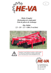
UK
Operating Instructions
Declaration of Conformity
Spare Parts List
Sub-Tiller
2.5 m / 3.0 m / 3.5 m / 4.0 m (rigid)
Important: Before using the machine, please study
the Operating Instructions thoroughly to ensure
that you are familiar with the safety instructions.
N. A. Christensensvej 34
DK-7900 Nykøbing Mors
Tel: +45 9772 4288
Fax:+45 9772 2112
www.he-va.com
Sub-Tiller 2.5 m / 3.0 m / 3.5 m / 4.0 m
2
06/08 2007
Sub-Tiller 2.5 m / 3.0 m / 3.5 m / 4.0 m
06/08 2007
Contents
Declaration of Conformity ......................................................................................................................... 4
Delivery check ............................................................................................................................................. 5
Machine Description ................................................................................................................................... 5
Range of Application ................................................................................................................................ 5
Technical specifikations............................................................................................................................ 5
Safety instructions for Sub-Tiller .............................................................................................................. 6
Safety and Instructions on Hydraulics...................................................................................................... 7
Labels on the machine ................................................................................................................................ 8
Start-up of the machine .............................................................................................................................. 9
General information .................................................................................................................................. 9
Attachment and uncoupling (rigid machines)........................................................................................... 9
Attachment and uncoupling (machines with hydraulic folding)............................................................... 9
Change-over between working and tranport position (only machines with hydraulic folding) ............... 9
Settings and adjustment ........................................................................................................................... 10
Stone protection ...................................................................................................................................... 10
Replacement of wearing point ................................................................................................................ 12
Scraper .................................................................................................................................................... 12
Maintenance .............................................................................................................................................. 13
Lubrication .............................................................................................................................................. 13
Spare parts list........................................................................................................................................... 14
Frame 2.5 4.0 m rigid........................................................................................................................... 14
Tine with Quick-Push shear bolt............................................................................................................. 16
Tine with hydraulic automatic release system ........................................................................................ 17
Accumulator for hydraulic automatic release system ............................................................................. 18
Scraper .................................................................................................................................................... 19
Multi-Seeder Mounting........................................................................................................................... 20
Multi-Seeder............................................................................................................................................ 21
Spare parts list
Hydraulics.................................................................................................................... 22
Hydraulics for depth control of the roller ............................................................................................... 22
Hydraulics for automatic release system ................................................................................................ 23
Notes ........................................................................................................................................................... 25
3
Sub-Tiller 2.5 m / 3.0 m / 3.5 m / 4.0 m
DS/EN 45 014
Declaration of Conformity
HE-VA ApS
N. A. Christensensvej 34,
DK-7900 Nykøbing Mors
declares under sole responsibility that the product:
Sub-Tiller
2.5 / 3.0 / 3.5 / 4.0 m (rigid)
No.: _____________
to which this declaration relates, is in conformity with the provisions of
98/37/EF (Machinery) Directive with later amendments.
Nykøbing Mors, 20 March 2007
4
06/08 2007
Sub-Tiller 2.5 m / 3.0 m / 3.5 m / 4.0 m
06/08 2007
Delivery check
Upon delivery to the dealer/supplier as well as to the customer, check the Sub-Tiller for possible
damages.
Machine Description
Range of Application
The Sub-Tiller is a sub-soiler for soil loosening from 0 cm to 60 cm depth. The work is preformed either
before seeding (min. tillage) or after harvest where a loosening of the tramlines in the field is desirable in
order to discourage structure damages. Infinitely variable tine spacing, depending on the actual working
task. The Sub-Tiller is ideal for all soil types and a V-profile roller is recommendable for moist and sticky
soil types while a square tube roller is recommendable for lighter soil types. The Sub-Tiller can be
mounted with HE-VA Multi-Seeder which opens up the possibility of till-seeding of rape or crops for
green manure.
The Sub-Tiller is mounted in the tractor s three-point suspension, and the hydraulic depth control via the
packer roller is controlled by the hydraulic system of the tractor. In order to achieve optimum control you
have to be aware of the tractor wheels, und under certain circumstances a mounting of twin wheels is
recommendable.
Technical specifications
2.5 m
3.0 m
3.5 m
4.0 m
4.0 m
5.0 m
hydr.
hydr.
Working width ...........................2.5 m ........ 3.0 m ........ 3.5 m......... 4.0 m......... 4.0 m......... 5.0 m
Transport width .......................... 2.5m ......... 3.0 m ........ 3.5 m......... 4.0 m......... 2.4 m......... 2.4 m
Height folded.................................. .................. .................. .................. ............. 2.6 m......... 3.0 m
Power requirement, HP ............ 60-120 ...... 60-180 ..... 140-280 .... 210-280..... 200-280..... 210-360
Weight w/V-profile roller and
Quick-Push shear bolt ..............1500 kg .... 1850 kg..... 2200 kg..... 2380 kg..... 2730 kg..... 3260 kg
Weight w/V-profile roller and
hydr. auto. release system ........1605 kg .... 2025 kg..... 2440 kg..... 2620 kg..... 2970 kg..... 3690 kg
Weight w/square tube roller and
Quick-Push shear bolt ...............985 kg ..... 1230 kg..... 1480 kg..... 1560 kg..... 1910 kg..... 2240 kg
Weight w/square tube roller and
hydr. auto. release system ........1090 kg .... 1410 kg..... 1720 kg..... 1640 kg..... 1990 kg..... 2390 kg
Number of tines........................2-3 pcs..... 2-3-5 pcs. ....5-7 pcs........ 7 pcs.......... 7 pcs........ 7-9 pcs.
Oil outlet ............................................................................... 1 double-acting outlet on rigid machines
Oil outlet ...................................................................... 2 double-acting outlets on hydraulic machines
Sub-Tiller complies with DS/ISO 11001-1, three-point suspension.
5
Sub-Tiller 2.5 m / 3.0 m / 3.5 m / 4.0 m
06/08 2007
Safety instructions for Sub-Tiller
Do not start-up the machine if there are persons in exposed positions* within a hazardous area**.
When persons are in exposed positions (e.g. in connection with adjustment, maintenance, attachment and
uncoupling), the following conditions shall be observed:
1.
The machine shall be lowered to firm ground.
2.
The hydraulics shall be relieved.
3.
The tractor shall be stopped and the key removed from the ignition switch.
4.
The driver shall ensure that no persons are staying in exposed positions during the operation.
*
**
Person in exposed position: Any person who is staying wholly or partly within a hazardous area.
Hazardous area: On and under the machine within a distance of 4 m from the machine.
Most accidents that happen in connection with the operation, transport and maintenance of machines are
caused by non-compliance with the most elementary safety conditions.
Therefore it is vital that anybody working at the machine carefully complies with the safety instructions
as well as other instructions applying to the machine.
The machine may only be operated, maintained and repaired by persons, who are familiar with this work
and who are further familiar with the possible elements of danger with this particular machine.
ATTENTION !!
Rotary parts and loose clothes are a dangerous combination.
IMPORTANT !!
In connection with the risk of parts falling down, it may endanger the
lives of persons staying on the base frame of the machine, when it is
operated attached to a tractor.
6
Sub-Tiller 2.5 m / 3.0 m / 3.5 m / 4.0 m
06/08 2007
Safety and Instructions on Hydraulics
1.
The maximum working pressure is 225 bar.
2.
It is advisable to label the attachment parts at hydraulic connections between the tractor and the
tool in order to eliminate incorrect operation!
3.
When checking for hydraulic leaks, use suitable safety wear (eye protectors, gloves, etc.)
High-pressure hydraulic oil may penetrate the skin and cause dangerous injuries.
In case of injury, consult a doctor immediately. RISK OF INFECTION!
5.
Before operating the hydraulics, lower the machine to firm ground.
Relieve the hydraulics, stop the motor and remove the ignition key.
6.
Check the hydraulic hoses on a regular basis, however, every six months as a minimum due to any
cracks, wear and tear, etc. Replace any defective hoses immediately.
The life of hydraulic hoses is maximum 5 years.
New hydraulic hoses shall meet the manufacturer's requirements.
INSTRUCTIONS ON TRANSPORT ON THE PUBLIC ROADS:
Check before transport on public roads that the attachment of the machine at the tractor is in accordance
with the local rules and regulations in force (permitted total weight, permitted axle load, transport width,
lights, warning signs, etc.).
FRONT AXLE LOAD:
After the attachment of the machine and at maximum load, the driving properties of the tractor shall be
ensured. Check that the front axle is sufficiently loaded. As a minimum, the front axle load shall be 20%
of the tractor weight. Permitted axle load and permitted total weight for the tractor shall always be
observed.
NB! The driving, controlling and braking properties are affected by the attached machine
combination.
7
Sub-Tiller 2.5 m / 3.0 m / 3.5 m / 4.0 m
06/08 2007
Labels on the machine
You will find several labels on your machine containing safety and practical instructions as regards the
correct application of the machine. Please study the instructions and point out to the user the importance
of the labels as well as the safety instructions in the Operating Instructions. Always keep the labels clean
and readable if not they must be replaced.
A
B
C
Explanation of the machine labels
A
Plate with number and year of manufacture.
B
Study the Operating Instructions thoroughly before any operation of the machine and
observe all safety instructions.
C
Tighten up all bolts regularly. If this is not performed, our guarantee obligations will no
longer apply.
8
Sub-Tiller 2.5 m / 3.0 m / 3.5 m / 4.0 m
06/08 2007
Start-up of the machine
General information
The machine requires 1 double acting outlet (rigid) or 2 double acting outlets (hydraulic folding).
The hoses for depth adjustment are provided with red cable straps.
The hoses for the folding are provided with blue cable straps.
Attachment and uncoupling (rigid machines)
1. Under normal circumstances attach the tractor in the lowest lifting points of the machine both as
regards the lifting arms and the top link.
2. When the machine is to be parked and uncoupled from the tractor, it is important, that the roller is
placed in the lowest position, so that the machine is placed stably.
3. When uncoupling, relieve the tractor s oil outlet, and the machine s quick couplings can be
uncoupled without pressure. The hydraulic cylinder which controls the roller is equipped with a
pilot-controlled check valve which hermetically cuts off the oil for the hydraulic cylinder,
meaning that it is locked in the chosen position regardless of the tightness of the quick couplings.
Attachment and uncoupling (machines with hydraulic folding)
1. Please note that these machines are to be attached and uncoupled in transport position.
If the roller is not placed to the bottom, problems with
the folding might occur.
Change-over between working and transport position (only machines with hydraulic folding)
From transport into working position:
1. The machine is lifted to max. transport height.
2. The cylinder for depth adjustment is placed to the top.
3. Unfold the wing sections.
4. Adjust the working depth.
From working into transport position:
1. The machine is lifted to max. transport height.
2. The cylinder for depth adjustment (the roller) is placed to the top.
3. The wing sections can be folded in.
Be sure that the check pawls lock the wing sections.
9
Sub-Tiller 2.5 m / 3.0 m / 3.5 m / 4.0 m
06/08 2007
Settings and adjustment
Stone protection
Quick-Push shear bolt.
When the shear bolt is broken and the tine has been released, place the shear bolt one notch forward
before the machine can operate again.
1. Pull out the R-clip (Pos. 1).
2. Pull the tine back to normal working position (Pos.
2).
3. Push the shear bolt (Pos. 3) one notch forward to a
new position in the tine. Do not push the bolt
totally through (it can be necessary to remove soil
etc. from the hole in the tine).
3
1
2
Important: All activities under the machine are
deprecated when the shear bolt is being moved or
changed.
4. Push back the R-clip (Pos. 1), so that it locks the
shear bolt in its place, and the machine is ready for
operation.
When the shear bolt is broken for the eighth time, it is used up. Be aware that the shear bolt must never
be shorter than 65 mm.
When a new shear bolt is mounted it is important that it is placed rightly. The end of 40 mm (Pos. 3) is to
turn away from the tine.
10
Sub-Tiller 2.5 m / 3.0 m / 3.5 m / 4.0 m
06/08 2007
Hydraulic automatic release system.
1
2
3
4
1. Before each season it has to be controlled, that the gas
pressure in the accumulator (Pos.1) is 90 bars.
This
requires special tools and can only be preformed by an
authorized dealer.
2. Before the start-up of the machine the hydraulic pressure in
the closed hydraulic stone protection system has to be
controlled on the machine s pressure gauge (Pos. 2). The
pressure has to be approx. 120 bar. It can be adjusted after the
conditions.
3. IMPORTANT the hydraulic pressure is to be controlled
continuously and must never be under 190 bar.
4. If there is a need to adjust the working pressure, follow the
below instructions:
a. Mount the quick coupling of the hydraulic hose (Pos.
3) in the tractor s oil outlet.
b. Turn on the ball valve (Pos. 4), and the working
pressure can now be adjusted up or down with the
tractor s oil outlet.
c. When the desired pressure is achieved, turn off the ball
valve again (Pos. 4), and the tractor s hydraulic system
is relieved before the quick coupling (Pos. 3) is
dismounted and placed in the parking device of the
machine.
5. During the operation of the machine the tine is swinging
automatically to the rear if it meets an obstacle. In normal
circumstances the tine will automatically return to the working
position again after having passed the obstacle. At extreme
obstacles and/or soil conditions it might be necessary to stop
and eventually lift the machine from the soil.
It is
important that no persons are near to the machine as the tine is
returning to the working position with high speed and might
throw with soil and stones.
11
Sub-Tiller 2.5 m / 3.0 m / 3.5 m / 4.0 m
06/08 2007
Replacement of wearing point
1.
2.
1
3.
4.
2
5.
6.
7.
Before working with the machine s wearing points, the
machine is to be fastened. This can be performed by trestles
under the main frame or by a support of the roller.
Dismount M16x65 mm bolt (Pos. 1) by means of 2 pcs. 24
mm spanners.
The wearing point might fall off, when the
bolt is removed take care of foot and leg injuries.
Dismount the wearing point by pushing it forward. This
might be difficult due to entrance of soil, and it might be a
good idea to use a hammer.
Mount the new wearing point, item no. 645000044 (Pos. 2),
by pushing the wearing point to the rear and then in its place.
Check the M16 x 65 mm bolt for eventual damages and
replace it as required, item no. 690103190 + 690113008.
Mount the M16 x 65 mm bolt (Pos. 1), lubricate and tighten
it with 197 Nm.
Check that the breast wearing part of the wearing point is
placed straight in front of the tine otherwise loosen the bolt
again (Pos. 1) and the wearing point is kept in its place while
the bolt (Pos. 1) is tightened again.
Scraper
The Sub-Tiller has special designed scrapers among the
packer rings on the V-profile roller.
To avoid unnecessary wear and to obtain the best scraper
effect it is important to check the centering of the
scrapers every day.
12
Sub-Tiller 2.5 m / 3.0 m / 3.5 m / 4.0 m
06/08 2007
Maintenance
After 10 hours of operation, retighten the machine. Check hydraulic hoses, fittings and cylinders
for leaks and retighten.
Further check on a regular basis that all bolts are tightened.
Before the winter storage, wash and lubricate the machine. If you use high-pressure cleaner, do
not spray directly on the ball bearings. After the washing, you may spray the machine with oil.
Lubrication
For lubrication, maintenance and repair, lower the Sub-Tiller, put the brakes of the tractor on and stop the
motor.
The 2.5 4.0 m Sub-Tiller (rigid) have five lubricating points, the 4.0 m 5.0 m Sub-Tiller (hydr.) have
20 lubricating points. All Sub-Tillers shall be lubricated after every 30 working hours as well as after the
cleaning in order to press out any water and dirt. The lubricating points on the rigid machines are located
where the bar is mounted on the frame as well as at ball bearings and cylinders.
X
Lubricating point
On the hydraulic models there are further lubricating points, where the side sections are hinged on the
middle section and at the locking mechanism of the side sections on the middle section.
Moreover, the machines with hydraulic automatic release system have 2 lubricating points per tine which
are to be lubricated after 10 hours of operation.
Attention!
However, the double-sealed ball bearings in the roller
should only by lubricated every 20 working hours and by
1-2 strokes so that the sealing rings are not pressed out.
Important!
Oil, type Hydro Texaco HD32 has
been filled in the hydraulic system.
13
Sub-Tiller 2.5 m / 3.0 m / 3.5 m / 4.0 m
06/08 2007
Spare parts list
Frame 2.5 4.0 m rigid
Pos.
1
1
1
1
2
3
4
4
4
Item no.
645000149
645000002
645000090
645000138
69537105C
69532105C
645000153
645000027
645000156
Designation
Frame 2.5 m
Frame 3.0 m
Frame 3.5 m
Frame 4.0 m
Pin for lift arm Ø37/Ø50 L=105
Pin for top link Ø32/Ø45 L=105
Roller bar 2.5 m
Roller bar 3.0 m
Roller bar 3.5 m
14
2.5 m
1
3.0 m
3.5 m
4.0 m
1
1
2
1
1
2
1
2
1
1
1
1
2
1
Sub-Tiller 2.5 m / 3.0 m / 3.5 m / 4.0 m
Pos.
4
5
6
7
8
9
10
11
12
13
14
15
16
17
18
19
20
21
22
23
23
23
23
24
25
26
Item no.
645000157
69430145G
690101101
690134004
690134008
630532600
690136029
645000036
69430200G
69430125G
645000162
690117012
690103076
690113005
645000165
690110101
690117013
690113008
690140808
630936300
630916300
630916350
630926300
690117005
690103147
690113009
Designation
Roller bar 4.0 m
Pin Ø30 L=145
Bolt M12x25 8,8 (set screw)
Ring pin Ø10 (ordinary head)
Ring pin Ø10 (big head)
Lock bush for pin head
Lubricating nipple M8
Cylinder for depth adjustment
Pin Ø30 L=200
Pin Ø30 L=125
Scale for depth control
Facet plate Ø10
Bolt M10x40 8.8 (set screw)
Self-locking nut M10
Pointer for depth control
U-bolt M16 100x100x100
Facet plate Ø16
Self-locking nut M16
Bearing UCF 312
V-profile roller 2435 mm
V-profile roller 2935 mm
V-profile roller 3435 mm
V-profile roller 3935 mm
Facet plate Ø20
Bolt M20x65 8.8
Self-locking nut M20
15
06/08 2007
2.5 m
3.0 m
3.5 m
2
4
1
2
4
3
1
1
1
1
4
2
2
1
1
2
2
2
1
2
4
1
2
4
3
1
1
1
1
4
2
2
1
1
2
2
2
2
4
1
2
4
3
1
1
1
1
4
2
2
1
1
2
2
2
4.0 m
1
2
4
1
2
4
3
1
1
1
1
4
2
2
1
1
2
2
2
1
1
16
8
8
16
8
8
16
8
8
1
16
8
8
Sub-Tiller 2.5 m / 3.0 m / 3.5 m / 4.0 m
06/08 2007
Tine with Quick-Push shear bolt
Pos.
1
2
3
4
5
6
7
7
8
9
10
11
12
13
Item no.
645000062
645000044
690103190
690117013
690113008
645000046
645000055
645000051
690117060
690103136
645000059
69435070F
690134004
0377600
Designation
Tine for Quick-Push
Wearing point
Bolt M16x65 8.8
Facet plate Ø16
Self-locking nut M16
Clamping plate
Tine bracket (left)
Tine bracket (right)
Facet plate Ø16 (hardened)
Bolt M16x90 10,9
Shear bolt Ø34
Pin Ø35 L=71
Ring pin Ø10
R-clip 6 mm electroplated
16
Number
per leg
1
1
1
2
9
1
1
1
16
8
1
1
1
1
Sub-Tiller 2.5 m / 3.0 m / 3.5 m / 4.0 m
06/08 2007
Tine with hydraulic automatic release system
Pos.
1
1
2
3
4
5
6
7
8
9
10
11
12
Item no.
645000124
645000072
645000086
645000044
690103190
690117013
690113008
645000046
690103136
690117060
645000113
690200305
690115014
Designation
Tine bracket for hydr. automatic release system (left)
Tine bracket for hydr. automatic release system (right)
Tine for hydraulic automatic release system
Wearing point
Bolt M16x65 8.8
Facet plate Ø16
Self-locking nut M16
Clamping plate
Bolt M16x90 10,9
Facet plate Ø16 (hardened)
Bush for hydraulic tine
Cylinder 110/50x165 with yoke
Facet plate Ø30
17
Number
per leg
1
1
1
1
1
2
9
1
8
16
1
1
2
Sub-Tiller 2.5 m / 3.0 m / 3.5 m / 4.0 m
13
14
15
16
17
18
19
690103868
690113018
69440165G
69440195G
630532600
690101101
690136029
Bolt M30x95 10.9
Self-locking nut M30
Pin Ø40 L=165
Pin Ø40 L=195
Lock bush for pin head
Bolt M12x25 8,8 (set screw)
Lubricating nipple M8
06/08 2007
1
1
1
1
2
2
2
Accumulator for hydraulic automatic release system
Pos.
1
2
3
4
5
6
Item no.
645000125
690110103
690117013
690113008
690206516
690206513
Designation
Support for accumulator for rigid frame
U-bolt M16x100x150x100
Facet plate Ø16
Self-locking nut M16
Clamp (175 -> 187 mm)
Accumulator 4l 185 bar
18
Number
1
2
4
4
2
2
Sub-Tiller 2.5 m / 3.0 m / 3.5 m / 4.0 m
06/08 2007
Scraper
Pos.
1
1
1
1
1
2
2
3
4
5
6
7
8
9
10
Item no.
645000287
630918550
630918150
630928550
630938550
630928560
630938560
690110106
690117013
690113008
630938522
630938526
690103086
690117014
690113006
Designation
Scraper bar with bracket
Scraper bar with bracket
Scraper bar with bracket
Scraper bar with bracket (right)
Scraper bar with bracket (right)
Scraper bar with bracket (left)
Scraper bar with bracket (left)
U-bolt M16x200x100x2000
Facet plate Ø16
Self-locking nut M16
Clamp for scraper (50x70)
Scraper, short, fixed roller bar
Bolt M12x90 8.8
Facet plate Ø12
Self-locking nut M12
19
2.5 m 3.0 m 3.5 m 4.0 m
4.0 m
5.0 m
hydr.
1
1
1
1
1
1
1
4
8
8
19
19
19
19
19
4
8
8
23
23
23
23
23
4
8
8
27
27
27
27
27
8
16
16
31
31
31
31
31
1
8
16
16
31
31
31
31
31
1
8
16
16
39
39
39
39
39
Sub-Tiller 2.5 m / 3.0 m / 3.5 m / 4.0 m
06/08 2007
Multi-Seeder Mounting
Pos.
1
2
2
2
2
3
4
5
6
7
8
9
Item no.
645000274
645000275
645000276
645000277
645000278
645000284
645000285
690210223
690210224
690210225
690103040
690110050
Designation
Plate for mounting of C-profile
C-profile for mounting of seed tube outlet 2.5 m
C-profile for mounting of seed tube outlet 2 m
C-profile for mounting of seed tube outlet 3.5 m
C-profile for mounting of seed tube outlet 4 m
Seed tube outlet for Sub-Tiller, straight
Seed tube outlet for Sub-Tiller, bended
Tube support Ø25, single
Welding plate for single tupe-support Ø25
Top plate for tube-support Ø25, single
Bolt M6x50
U-bolt M12 40x40x40
20
Number
2
1
1
1
1
1
2-9
2-9
2-9
2-9
6-14
2
Sub-Tiller 2.5 m / 3.0 m / 3.5 m / 4.0 m
10
11
12
13
14
15
15
16
17
18
19
20
21
22
23
24
25
26
27
28
29
30
31
32
33
34
690117014
690113006
690110106
690117013
690113008
645000065
645000290
690117012
690113005
690110103
645000099
645000111
690117005
690103159
690113009
645000109
69516094A
690133005
690103117
0539055
690109306
645000286
0272240
690103042
0264040
690103031
06/08 2007
Facet plate Ø12
Self-locking nut M12
U-bolt M16x200x100x200
Facet plate Ø16
Self-locking nut M16
Seed hopper plate 200 l
Seed hopper plate 400 l
Facet plate Ø10
Self-locking nut M10
U-bolt M16x100x150x100
Suspension for driving wheel
Pivoting arm for driving wheel
Facet plate Ø20
Bolt M20x120 8.8
Self-locking nut M20
Flange for suspension for driving wheel
Pin for support stand Ø16 L=94 mm
R-clip Ø4
Bolt M16x110 8.8
Seed hose
Clamp 26-38 mm 12 mm wide
Bracket for seed tube outlet
Facet plate 6 mm, fzb
Bolt M6x60 8.8
Self-locking nut M6, fzb DIN985
Bolt M6x40
4
4
4
16
14
1
1
8
8
2
1
1
2
1
1
1
1
1
2
2-9
2-9
2
12
4
4
4
Attention:
The number of hoses and hose lengths can vary - dependent on the machine type, therefore check
measurements and number before ordering the spare parts.
Multi-Seeder
If the Sub-Tiller is mounted with HE-VA Multi-Seeder, we refer you to the Operating Instructions for
Multi-Seeder.
21
Sub-Tiller 2.5 m / 3.0 m / 3.5 m / 4.0 m
06/08 2007
Spare parts list Hydraulics
Hydraulics for depth control of the roller
Pos.
1
2
3
3
3
3
4
5
6
7
8
9
10
Item no.
690203001
690203003
690201046
690201013
690201041
690201225
690203006
662000804
690203111
690203110
690203016
690203002
645000036
11
690202971
Designation
Quick coupling, male E402 ½
Fitting, straight 10-1/2 BSP
Hydraulic hose 1660 mm 1/4 st/st
Hydraulic hose 1770 mm 1/4 st/st
Hydraulic hose 1850 mm 1/4 st/st
Hydraulic hose 1975 mm 1/4 st/st
Fitting, 90angle 10-3/8 BSP
Hydraulic tube Ø12 L=106
Union nut Ø12
Olive ring Ø12
Fitting 90angle 10 mm
Fitting, straight 10-3/8 BSP
Cylinder for depth adjustment
Check valve (pilot-controlled, double)
3/8"
22
2.5 m
2
2
2
3.0 m
2
2
3.5 m
2
2
4.0 m
2
2
2
2
2
2
4
4
2
2
1
2
2
4
4
2
2
1
2
2
4
4
2
2
1
2
2
2
4
4
2
2
1
1
1
1
1
Sub-Tiller 2.5 m / 3.0 m / 3.5 m / 4.0 m
06/08 2007
Hydraulics for automatic release system
Pos.
1
2
3
4
5
6
7
8
9
10
Item no.
690206513
690204501
690204512
690204500
690204502
690204503
690204504
662000803
690204505
690204506
Designation
Accumulator 4L 185 bar
Fitting straight 1/2 x 1 1/4
Fitting straight 15 mm x 1/2
Fitting 90angle Ø 15 mm
Fitting T15L
Olive ring Ø15
Union nut Ø15
Hydraulic tube Ø15 L=38
Fitting T15
Reversed fitting Ø15 / 1/2
23
Number
2
2
2
2
2
2
2
1
1
1
Sub-Tiller 2.5 m / 3.0 m / 3.5 m / 4.0 m
Pos.
11
12
13
14
15
16
17
18
19
20
21
22
23
24
25
Item no.
690203314
690206824
690206825
690202990
690203002
690201032
690203003
690203001
690201448
690201430
690201447
690204507
690206002
690204512
690200305
Designation
Fitting T 3/8 / 12 / 12
Pressure gauge 400 bar
Pressure gauge fitting Ø12 / 1/4
Ball valve 3/8" PN500 DN 10
Fitting, straight 10-3/8" BSP
Hydraulic hose 1130 mm 1/4 st/st
Fitting, straight 10-1/2" BSP
Quick coupling 1/2" E402, male
Hydraulic hose 1150 mm 1/2" st/45
Hydraulic hose 590 mm 1/2" st/45
Hydraulic hose 300 mm 1/2" st/st
Fitting T15
Filter plug (ventilation) ½
Fitting, straight 15 mm x 1/2"
Cylinder 110/50x165 with yoke
06/08 2007
Number
1
1
1
1
1
1
1
1
2
0-9
0-1
0-7
2-9
2-9
2-9
Attention:
The number of hoses and hose lengths can vary - dependent on the machine type, therefore check
measurements and number before ordering the spare parts.
24
Sub-Tiller 2.5 m / 3.0 m / 3.5 m / 4.0 m
Notes
25
06/08 2007
Sub-Tiller 2.5 m / 3.0 m / 3.5 m / 4.0 m
26
06/08 2007
The design is subject to modification without notice.