1
smart: series of micro-processor controlled speed controllers
operating instructions for software V4, date of issue 02 OCT 1997
4
.
elektronik
gmbh
page 1
.
3
6 - 32 Ni-Cd
Zellen
Inenn 75A
Imax 150A
schulze
made in
germany
akku
motor
smart-75bo
5
schulze
1
LED:
on back side of pcb
2
08.97 v22
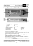
Key to illustrations:
1. Receiver cable (3-pin)
2. Battery connection, negative (-) terminal, black
3. Battery connection, positive (+) terminal, red
4. Motor connection, positive (+) terminal, red
5. Motor connection, negative (-), yellow
Chapter Subject
Page
1
Warning notes, cautions
2
Ensuring safe, trouble free operation
. . . . . . . . . . . . . . . . . .
3
3
Intended applications . . . . . . . . . . . . . . . . . . . . . . . . . . .
4
4
Technical data . . . . . . . . . . . . . . . . . . . . . . . . . . . . . . .
4
5
Protective circuits . . . . . . . . . . . . . . . . . . . . . . . . . . . . .
5
6
Monitor displays . . . . . . . . . . . . . . . . . . . . . . . . . . . . . .
5
7
Connector systems and mounting instructions . . . . . . . . . . . . .
6
8
Installing and connecting the unit
. . . . . . . . . . . . . . . . . . . .
7
9
Using the controller for the first time . . . . . . . . . . . . . . . . . . .
7
9.1
Symbols and terminology . . . . . . . . . . . . . . . . . . . . . . . . . .
7
9.2
ips - the intelligent programming system . . . . . . . . . . . . . . . . . .
8
9.2.1
Normal operation - propeller brake mode . . . . . . . . . . . . . . . . . .
8
9.2.2
No - brake mode
8
9.2.3
Use with self-neutralising stick
9.2.4
Helicopter mode
10
Legal matters
. . . . . . . . . . . . . . . . . . . . . . . . .
. . . . . . . . . . . . . . . . . . . . . . . . . . . . . .
2
. . . . . . . . . . . . . . . . . . . . . . .
9
. . . . . . . . . . . . . . . . . . . . . . . . . . . . . .
9
. . . . . . . . . . . . . . . . . . . . . . . . . . . . . . .
10
10.1
Warranty
. . . . . . . . . . . . . . . . . . . . . . . . . . . . . . . . . . 10
10.2
Limited liability / damages . . . . . . . . . . . . . . . . . . . . . . . . . . 10
10.3
CE certification
. . . . . . . . . . . . . . . . . . . . . . . . . . . . . . . 10
schulze elektronik gmbh • prenzlauer weg 6 • D-64331 weiterstadt • tel: 06150/1306-5, fax: 1306-99
internet: http://www.schulze-elektronik.com
e-mail: [email protected]
page
2
smart: series of micro-processor controlled speed controllers
1 Warning notes, cautions
Electric motors fitted with propellers are dangerous and require proper care for safe operation. Keep well clear of the propeller at all times
when the battery pack is connected.
Technical defects of an electrical or mechanical
nature may result in unintended motor runs;
loose parts may cause serious personal injuriy and/or property damage.
The CE-certificate on the speed controller does
not absolve you from taking proper care
when handling the system!
Speed controllers and soft-switches are exclusively for use in RC models. Their use in
man-carrying aircraft is prohibited.
Speed controllers and softswitches are not protected against reverse polarity (+ terminal
and - terminal reversed). Connecting the
battery pack to the motor leads of the controller or soft-switch will almost certainly
cause irreparable damage.
Electronic equipment is sensitive to humidity.
Speed controllers and soft-switches which
have got wet may not function properly even
after thorough drying. You should send
them back to us for cleaning and testing.
Do not use speed controllers in conjunction with
a power supply connected to the mains. Energy reversal can occur when the motor slows
down and stops, and this may damage the
power supply or cause an over-voltage condition which could damage the controller.
Never disconnect the flight pack while the motor is running, as this could cause damage
on a speed controller or a soft-switch.
On no account connect a separate receiver battery or an electronic battery switch (two receiver batteries), as this may cause damage
to the speed controller and could cause current to flow from the receiver battery to the
motor. If you want to use a separate receiver
battery cut through the + wire in the receiver cable, or pull it out of the connector if possible.
However, for greater protection against motorinducted interference it is always better to use a
speed controller with an opto-coupler.
Protect the speed controller or soft-switch from
mechanical loads, vibration, dirt and contamination.
Keep the cables to the battery and to the motor
as short as possible.
Never leave the flight battery connected when ...
... the model is not in use and/or
... the battery pack is being charged.
(Although some speed controllers feature a
separate On/Off switch, this does not isolate
it completely from the battery.)
Note the limited capacity of the BEC system
when used with a high number of cells in the
flight pack (see Specification, Section 4).
Speed controllers and soft-switches can only
function properly if they are in full working
condition. The protective and monitoring circuits can also only work if the speed controller is in good operating condition.
In the case of motor failure (e.g.short
circuits in the windings) the over-temperature sensor in the controllers may
react too slowly to prevent damage.
Switch the motor off immediately to
prevent permanent damage to the
speed controller.
If a transistor fails in the throttle stage,
neither a "stop" signal from the transmitter nor the temperature monitor nor the
current limiter will be able to throttle back
or stop the motor.
Note: Please remember that the monitoring circuits are unable to detect every abnormal
operating condition, such as a short between the motor cables. Note also that a
stalled motor will only trip the current limiter
if the motor's stall current is well above the
controller's peak current. For example, if
you are using an 80 A controller in conjunction with a 20 A motor, the current monitor will not detect an excessive current even
when the motor is stalled.
schulze elektronik gmbh • prenzlauer weg 6 • D-64331 weiterstadt • tel: 06150/1306-5, fax: 1306-99
internet: http://www.schulze-elektronik.com
e-mail: [email protected]
smart: series of micro-processor controlled speed controllers
operating instructions for software V4, date of issue 02 OCT 1997
2 Ensuring safe, trouble-free
operation
Use only compatible connectors. A 2mm pin
cannot provide reliable contact in a 2.5mm
socket. The same applies with 2mm goldcontact pins and 2mm tin-plated sockets.
Please also remember that ...
... the wiring of your RC-components must
be checked regularly for loose wires, oxidation, or damaged insulation, especially when
using a BEC system.
... your motor is suppressed by at least two,
better: three, ceramic capacitors of 10 to
100nF / 63 to 100V. Extra suppression can
also be achieved using filters with coils.
... the CE certificate on the speed controller
does not absolve you from the need to
handle the system carefully.
... your receiver and the aerial must be at
least 3 cm (>1") away from motor, speed
controller and high-current cables. For example, the magnetic fields around the highcurrent cables can cause interference to the
receiver.
... all high-current cables must be as short
as possible. Maximum length between flight
pack and speed controller should not exceed 20 cm (7"), between speed controller
and motor: 5 cm (2").
... all high-current cables longer than 5 cm
(2") must be twisted together. This applies
in particular to the motor power cables,
which are very powerful sources of radiated
interference.
... in model aircraft: half of the receiver
aerial's length should be routed along the
fuselage, the other half should be allowed to
trail freely (take care not to tread on it). Do
not attach the end of the aerial to the fin!
... in model boats: half of the receiver
aerial's length should be deployed inside the
hull above the waterline, the other half
should be threaded into a small tube mounted upright.
Every time you intend to use the power system - before you turn on the receiver -
schulze
elektronik
gmbh
page 3
make sure that ...
... no one else is using the same frequency
(identical channel number).
... your transmitter is switched on and the
throttle stick is (as a rule) in the STOP position (exceptions see Section 9).
Carry out a range check before each flight. Ask
an assistand to hold the model aircraft and
set the throttle stick to the half throttle position (full throttle if using a soft-switch). Collapse the transmitter aerial. Walk away from
the model to the distance stated by the RC
system manufacturer (this might be a distance of about 50-60 m = 200'). Make sure
that you still have full control of the system
at this range.
As a general rule: receiver interference is
more likely to occur when using a controller
or governor with BEC system, as these units
do not feature an opto-coupler with its optical link.
When Ni-Cd batteries approach the end of their
charge, voltage falls drastically and quickly.
The smart detects this and reduces power
to the motor automatically. This should leave sufficient energy to bring your model
safely back home. However, if you use a
small number of cells of high internal resistance and operate at high motor currents,
the controller may reduce power before the
pack is discharged. You can eliminate this
problem by using low resistance straps to
connect the cells, or use the direct cell-tocell soldering technique (“sticks”) and short,
heavy-gauge wire if you assemble your own
batteries.
Your receiver also benefits from the stability of
the voltage supplied from the battery. If the
BEC voltage is stable, the receiver is less
liable to suffer interference.
If you are using a mechanical gyro:
Always disconnect the flight pack before
turning off the receiver. As the gyro runs
down it may product sufficient voltage for
the receiver to send an unwanted signal to
the controller, and this could cause the motor to burst into life!
schulze elektronik gmbh • prenzlauer weg 6 • D-64331 weiterstadt • tel: 06150/1306-5, fax: 1306-99
internet: http://www.schulze-elektronik.com
e-mail: [email protected]
page
4
smart: series of micro-processor controlled speed controllers
3 Intended applications
Special features of individual controllers:
smart-47bo: a speed controller / current regulator
with opto-coupler, designed for use in small to
medium-sized models with 6 to 16 Ni-Cd cells.
smart-52bo: a speed controller / current regulator
with opto-coupler, designed for use in mediumsized models with 10 to 24 Ni-Cd cells.
smart-75bo: a speed controller with opto-coupler
offering high maximum load, a wide range of
cells and impressively low interference, and
therefore suitable for any application.
smart-70be: this controller is designed for use
with 6 to 12 Ni-Cd cells in models where it is
necessary to save the weight of a seperate
receiver battery. The high-capacity BEC circuit
can cope with very high peak currents, i.e. the
smart can be used with 4-6 servos.
Highlights common to all units:
Ultra-small, ultra-light units due to absence of
cooling fins.
Better than 200-step resolution over the whole
control range for extremely fine speed control.
Variable low voltage threshold, dependent on
number of cells and load. Avoids harmful
deep-discharge of cells which can result in
polarity reversal.
Controllers work reliably and without causing interference right down to the last usable scrap
of battery energy; our ultra-high capacity BEC
system (max. 3A) with enhanced BEC voltage
(5.2V) gives faster servo transit speeds
(smart-70be only).
Integral voltage converter produces an auxiliary
voltage for the Power MOSFETs, resulting
in ultra-low losses (smart-75bo and -70be).
High 2kHz pulse frequency, keeping the motor
and controller cool and shielding the receiver system from interference.
LED monitor.
"Auto-arm" function and "power-on reset".
“ips” (intelligent programming system) with no
pots! The speed controller automatically configures itself to the stick travel when you switch
your transmitter on. The brake can also be
disabled in the same way if required. During
the configuration process the motor acts as
a loudspeaker to give you audible confirmation of the procedure.
4 Technical data
Type
Strom
Ni-Cd Size
Weight Cable Thrott. Brake Coupling
[unit]
[A]
[cells] [mm]
[g]
[mm2] [mW] [mW]
smart-47bo 47/95
6-16 41 x 31 x 11 21-55 2.5
3.3
10
opto-coupler
smart-52bo 52/105 10-24 41 x 31 x 11 21-55 2.5
2.7
8
opto-coupler
smart-70be 70/140
6-12 52 x 31 x 11 33-65 4.0
2.5
3.3
BEC 5.2V/2.5A peak
smart-75bo 75/150
6-32 52 x 31 x 11 33-65 4.0
2
5.3
opto-coupler
Current rating: Maximum current / nominal current:
All smart feature a current monitor circuit which permits a high start-up current.
The maximum current limit will decrease gradually within 1.2 seconds to the nominal current value. The nominal current value is the continous current at which the
smart can be operated at full-throttle when connected to a 10V / 2Ah battery.
Weight:
excluding - including cables.
Throttle, brake: Internal resistance of FETs as stated in the maker's data sheets.
Other features: Overheating threshold approximately 110°C. Pulse frequency 2 kHz.
BEC:
5,2V; peak current 3A with 6 Ni-Cd cells, 2.5A/8 cells, 2A/10 cells, 1.5A/12 cells;
peak current can only flow for less than 1 second, followed by a cooling-off period.
The maximum permissible continous current is much lower and is limited by the
maximum power disspiation of the voltage regulator used. (No limiting circuits!)
The maximum power dissipation is about 2.5W, i.e. with a BEC voltage of 5.2V and a battery voltage of 9.6V (difference 4.4V) the maximum continous current is about 0.57A.
schulze elektronik gmbh • prenzlauer weg 6 • D-64331 weiterstadt • tel: 06150/1306-5, fax: 1306-99
internet: http://www.schulze-elektronik.com
e-mail: [email protected]
smart: series of micro-processor controlled speed controllers
operating instructions for software V4, date of issue 02 OCT 1997
schulze
elektronik
gmbh
page 5
5 Protective circuits
Note: the monitor circuits are effective, but they
cannot detect every possible operating condition.
Temperature monitor:
The temperature monitor throttles back the motor in two stages before switching it off entirely.
You can reset the unit using the "auto-arm"
function (throttle stick to stop for about 2 sec.)
If the motor windings are short-circuited the temperature monitor reacts too
slowly to prevent damage. Switch the
motor off immediately to avoid permanent damage to the speed controller.
Voltage monitor:
As soon as the voltage of the drive battery falls
back to about half the no-load voltage or the 5V
threshold the motor is throttled back. If voltage
continues to fall the controller switches off the
motor entirely. Of course, you can re-start the
motor again briefly by moving the throttle stick
back to "stop" for about 2 sec. to re-arm the system. The speed controller - and your model
aircraft - remain fully controllable until the last
drop of usable energy is exhausted.
We can not predict how long you can still control your model with the residual battery charge
as this depends on many parameters such as
the number of cells in the pack, the cell type,
actual motor current and the way you control
your model. The only solution is for you to time
the period yourself with the model on the
ground. If the voltage monitor trips, i.e. the motor starts to throttle back without your intervention, you should stop the motor at once with the
throttle stick in any case so that you have the
maximum possible reserve of power.
Current monitor:
Our smart controllers feature a current monitor
circuit which permits a high start-up current and
then gradually - within 1.2 seconds - reduces
the threshold value to the maximum permissible
continuous current. If the motor is stalled, the
controller limits the current drain. This means
that a motor which draws an excessive current
will never reach full throttle, and the current
stays below the specified maximum value. The
LED then glows at about half maximum brightness.
Receiver signal monitor:
If the receiver signal fails, or the signal is longer
or shorter than the usual range of values, the
smart controller reverts to hold mode for about
0.5 seconds before switching to disarmed mode.
Reverse polarity protection:
These speed controllers are not protected against reversed polarity!
Watchdog:
If this circuit is tripped the speed controller
stops working briefly and then reverts to normal
operation.
6 Monitor displays
Our smart controllers feature two LEDs (= one
Duo-LED) to help to understand the status of
the unit at any time. The meaning of the coloured lights is as follows:
100% brake: red,
full brightness, flashing
No-load: g & r, alternating flashing fast
10% forward: green, 10% brightness
90% forward: green, 90% brightness
100% forward: g & r, full brightness
Function:
No-load:
red / green,
Note:
alternating , flashing fast.
smart is "armed",
throttle and brake off.
Waiting for arming:
red / green, alternating, flashing slowly.
smart is "disarmed"
(always if full throttle is configured first)
Throttle stick to brake position activates smart.
Excess temperature:
red
flashing together.
Wait until temperature falls.
"Auto-arm" activates smart.
schulze elektronik gmbh • prenzlauer weg 6 • D-64331 weiterstadt • tel: 06150/1306-5, fax: 1306-99
internet: http://www.schulze-elektronik.com
e-mail: [email protected]
page
6
smart: series of micro-processor controlled speed controllers
7 Connector systems and mounting instructions
7.1 3.5 mm gold-contact connector system (pp35); max. load > 80A
+ red
plug
wide sleeve narrow
socket
+ red (
akku)
smart
Battery
- black
socket
narrow sleeve wide
plug
- black (
akku)
Caution: remove locating lug from battery cable. Do not remove lug from any cables attached to controllers or charge leads!
Fit the connectors in the order shown above; the contacts are pressed in as follows:
a. Place plastic sleeve vertically on table, grip end up.. b. Push contact down into sleeve.
c. Place 2,5mm wide screwdriver blade on top of cable solder joint inside sleeve.
d. Tap screwdriver to press contact into sleeve until latch engages.
7.2 4 mm gold-contact connector system (CT 4); max. load > 80A
+ red
sleeve wide
plug
socket
sleeve narrow red (
smart
Battery
- black
akku)
sleeve narrow
socket
plug
sleeve wide black (
akku)
Fit the connectors in the order shown above; the contacts are pressed in as follows:
a. Rest plastic sleeve on vice jaws with cables hanging down. b. Close vice jaws until cables are just free to move.
c. Fit plug into socket and tap into sleeve until latch engages.
d. Fit socket onto plug and tap into sleeve until latch engages.
7.3 MPX gold-contact connector system (green or red); max. load approx. 30A
+ red
heat-shrink
socket
plug
heat-shrink + red (
smart
Battery
- black
akku)
heat-shrink
socket
plug
heat-shrink
- red (
akku)
Fit the connectors in the order shown above; the contacts are soldered as follows:
a. To center the contacts fit plug and socket together before soldering. b. Tin all 6 exposed contacts of plug or socket.
c. Fit cable end into triangle of contacts, solder to all three contacts.
d. Position heat-shrink sleeve and shrink over joint.
7.4 2.0 / 2.5 mm gold-contact connector system; max. load approx. 30A
+ red
socket
sleeve narrow
sleeve wide
plug
akku)
smart
Battery
- black
+ red (
socket
sleeve narrow
sleeve wide
plug
- black (
akku)
Fit the connectors in the order shown above; the contacts are pressed in as described for the pp35 system.
schulze elektronik gmbh • prenzlauer weg 6 • D-64331 weiterstadt • tel: 06150/1306-5, fax: 1306-99
internet: http://www.schulze-elektronik.com
e-mail: [email protected]
smart: series of micro-processor controlled speed controllers
operating instructions for software V4, date of issue 02 OCT 1997
8
Installation, connections
schulze
elektronik
gmbh
page 7
9 Using for the first time
Installing in the fuselage:
Velcro (hoop and loop) tape is the ideal method of
mounting the controller in the fuselage. Do not pack
the smart in foam as this may lead to a heat buildtup in the controller.
9.1 Symbols and terminology
Length of connecting cables:
The cables to the flight battery and - in particular to
the motor - should be kept as short as possible. Long
cables tend to act as aerials and radiate interference;
they also add unnecessary weight. See also Section 2.
0% = minimum, stick usually pointing towards you;
100%=maximum, stick pointing away from you.
Power-connection battery <--> smart:
It is essential to use polarized gold-plated-contact
connectors - fitting any other type of connector invalidates the warranty.
Connectors which are not fitted as standard with a
polarized insulating sleeve can be effectively polarized by soldering the positive battery lead attached to
the smart to a socket, and the negative battery lead
attached to the smart to a plug.
Power-connection smart <--> motor:
Solder the blue (or yellow) and the red cable (length
max. 5cm = 2") directly to the motor terminals, or
shorten the existing motor cables. The overall length
of the connection after soldering should not exceed
5cm (2").
If you prefer to have a plug-in connection between
smart and motor, solder 2 sockets on the cable attached to the smart, and 2 plugs on the cable attached
to the motor. Fit the connectors as described in Section 7.1.
smart
2x socket
2x plug
motor
Receiver connection:
Connect the receiver cable attached to the smart to
the receiver servo output corresponding to the throttle stick (or a switch) on the transmitter.
The smart-70be supplies the receiver with its operating voltage via this output socket. For this reason,
check regularly that the receiver cable is undamaged
and firmly seated at the smart. On no account connect a separate receiver battery or an electronic battery switch (two receiver batteries), as this may cause damage to the smart-70be and could cause current to flow from the receiver battery to the motor. If
you want to use a separate receiver battery cut through
the + wire in the receiver cable, or pull it out of the connector if possible. However, for greater protection against motor-inducted interference it is always better to use a speed
controller with an opto-coupler.
Stick:
The throttle stick on the transmitter.
Brake position or neutral position:
Idle position, or position where the
motor just barely runs
Brake position or idle position:
Position of the throttle stick where the
motor stops or just barely runs.
Full-throttle position:
100% voltage passed to the motor
(speed controller mode), maximum configured motor rpm (governor mode).
Audible indicators:
These indicators are only audible
when a motor is attached, as the motor itself acts as the loudspeaker.
Single beep
e
Double beep
ee
Momentary interruption in running
(inverse beep)
(e)
Wait (0.5 seconds):
schulze elektronik gmbh • prenzlauer weg 6 • D-64331 weiterstadt • tel: 06150/1306-5, fax: 1306-99
internet: http://www.schulze-elektronik.com
e-mail: [email protected]
page
8
smart: series of micro-processor controlled speed controllers
9.2 ips, the intelligent programming system
for configuring the smart to suit your application
The ips reflects the initial set-up procedure used with our speed controllers until recently, i.e. the process of adjusting the
braking point with the help of a trim pot. For any normal application with an EMF brake (for a folding propeller) the startup procedure is entirely conventional: throttle stick to "motor stopped", switch first transmitter-, then receiver on, hold
model in lauch position, apply full throttle, launch.
The controller has to be adjusted to match the stick travel of your transmitter - a procedure we term "configuration" - and
with these units the process is fully automatic. If you wish to use the controller in a model which does not require a propeller brake, or in a model helicopter in which the full-throttle setting of the motor does not coincide with the maximum
collective pitch setting, the procedure is slightly different (see below). The brake point and the full throttle point must be
configured in such a way that full stick travel is always available to operate the motor, as this provides the finest possible level of control.
If you have a transmitter with adjustable servo travel we recommend that you set throttle-servo to normal full travel, i.e. +/- 100%.
A single beep always indicates that the controller is armed! When you next move the throttle stick, the motor
will start running. If the smart beeps twice when the transmitter stick is at the brake position (double beep =
full-throttle position), you must disconnect the controller and operate the servo reverse facility on your transmitter, otherwise the controller would arm itself (single beep) at the full-throttle setting of your transmitter and
would run at full throttle with the stick at the “stopped” position - the exact opposite of what is required.
9.2.1 Propeller brake mode
9.2.2 No-brake mode
a Receiver off and flight battery disconnected.
a Receiver off and flight battery disconnected.
b Set throttle stick to brake position.
b Set throttle stick to full-throttle position.
c
Switch transmitter on.
d Switch receiver on and connect
flight battery.
e smart confirms brake position with
a single beep, and is now armed!
f
TXon
RXon
e
Hold model in launch position,
keep clear of danger area around
propeller.
e smart confirms full-throttle position
with a double beep.
(e)
The smart is completely configured and the model can be flown.
TXon
RXon
ee
Move throttle quickly to idle position
and leave it there for about 1/2 second.
g smart confirms idle position with a
single beep, and is now armed!
e
h The smart is completely configured.
i
i
Switch transmitter on.
d Switch receiver on and connect
flight battery.
f
g Move throttle quickly to full-throttle
position and leave it there for about
1/2 second. Motor is already running - as with a conventional speed
controller.
h smart confirms full-throttle position
by interrupting the motor run very
briefly - a barely perceptible "blip".
c
Place the model in the launch position. Keep clear of danger area
around propeller. Open throttle in
the normal way to start the flight.
The configured data is retained in the smart until you disconnect the flight pack or switch off the BEC system.
schulze elektronik gmbh • prenzlauer weg 6 • D-64331 weiterstadt • tel: 06150/1306-5, fax: 1306-99
internet: http://www.schulze-elektronik.com
e-mail: [email protected]
smart: series of micro-processor controlled speed controllers
operating instructions for software V4, date of issue 02 OCT 1997
9.2.3 Propeller brake mode,
half stick travel
a Receiver off and flight battery disconnected.
b Set transmitter stick to neutral position = brake position (for the technically minded: pulse width smaller
than 1.65ms).
Switch transmitter on.
d Switch receiver on and connect
flight battery.
e smart confirms brake position with
a single beep, and is now armed!
f
TXon
RXon
e
The smart is completely configured
and the model can be flown.
c
Switch transmitter on.
d Switch receiver on and connect
flight battery.
f
g Move throttle quickly to full-throttle
position and leave it there for about
1/2 second. Motor is already running - as with a conventional speed
controller.
i
b Set the collective pitch stick to the
position in which the smart is required to provide full-throttle.
It is important that you can always
call up this precise point for the startup procedure. The best method is to
assign the value to one switch position of a Dual-Rate switch.
e smart confirms full-throttle position
with a double beep.
Place the model in the launch position. Keep clear of danger area
around propeller.
h smart confirms full-throttle position
by interrupting the motor run very
briefly - a barely perceptible "blip".
If the full throttle position is not confirmed, the smart cannot supply
full-throttle because stick travel between neutral point and full-throttle
point is "too short". If this happens,
set the servo travel for the throttle
channel as high as possible (e.g.
150%; the pulse width for the throttle channel must be at least 1.95ms)
elektronik
gmbh
page 9
9.2.4 Helicopter mode (no brake)
a Receiver off and flight battery disconnected.
c
schulze
(e)
TXon
RXon
RX
on
ee
Move throttle quickly to minimum
collective pitch (idle position) and
leave it there for about 1/2 second.
g smart confirms idle position with a
single beep, and is now armed!
e
h The smart is completely configured.
i
Place the helicopter in the take-off
position. Keep well clear of danger
area around rotor. Open throttle
gradually to start the flight.
Note: to avoid the motor stopping
completely when collective pitch is
reduced to minimum we recommend that you switch on idle-up after completing the configuration
procedure outlined above.
The configured data is retained in the smart until you disconnect the flight pack or switch off the BEC system.
[*] Note: This position must not be the hover point; it should be at least 30% in the direction of maximum collective pitch. For the technically minded: throttle channel pulse width at least 1.65ms.
schulze elektronik gmbh • prenzlauer weg 6 • D-64331 weiterstadt • tel: 06150/1306-5, fax: 1306-99
internet: http://www.schulze-elektronik.com
e-mail: [email protected]
page
10
smart: series of micro-processor controlled speed controllers
10 Legal matters
10.1 Warranty conditions
All schulze products are 100% dynamically tested by using a battery and a motor. We do not
simulate tests.
If your unit develops a problem, please return it
to schulze or to the importer. Include a description of the problem. Please be careful and
precise, and list the battery voltage and capacity, motor type, conditions under which failure
occured etc. A note saying “doesn't work” does
not help us much, and it may lead to waisted
time in trouble-shooting. Before returning the
unit for repair, please test it “one more time” carefully. If we find that the controller is operating
correctly, whether it is under warranty or not,
we will make a charge for our lost time.
One final note:
Please don't try trouble-shoot a defective unit
yourself. Very few hobby shops are equipped to
analyze and repair surface-mount printed circuit
boards. We reserve the right to refuse repair to
units which have been modified or “improved”
by unauthorized “experts”.
As we mentioned earlier, if you have a problem
with one of our products, please send it back to
us or our authorized representative (see catalogue). This ensures that the proper replacement parts will be used, and that you will gain
maximum pleasure from using these products.
You also have the comfort of a properly repaired unit with a renewed warranty. The guarantee period of repaired devices is applicable only
to the repair. This period is shorter than the
guarantee period of a new product (See our general conditions of business).
10.2 Liability / damages
We have invested a lot of effort in helping you
to exploit this unit to maximum. However, since
neither the manufacturer (schulze) nor the importer have control over how these products are
used, we cannot accept liability for any direct or
consequential damage, loss and/or injuries to
the user, to third-parties or the environment
from the use of this product. Taking into account our legal obligations, and regardeless of
the legal basis for any action, our liability to
compensate for damages shall be limited to the
invoice amount of the portion of the merchandise directly involved in the event which incurred the damages. This does not apply in respect of our unlimited liability due to wrongful
intend or gross negligence, as prescribed by
law.
10.3 CE certification
The products described in this manual are manufactured in accordance with all specific and
mandatory European CE guidelines:
EMI 89/336/EEC, 91/263/EEC and 92/31/EEC.
The products have been tested according to the
following norms:
EMI-emissions: EN 50 081-1:1992
EMI-resistance: EN 50 082-1:1992 or
EN 50 082-2:1995
The design and construction of our products
comply with the requirements for safe operation.
EMI emissions were tested under realistic conditions, i.e. using suitable motors close to the
maximum allowed currents. The use of resistors instead of motors do not create maximum
emission levels.
Further testing is carried out to ensure adequate EMI resistance against emissions from other
apparatus. The RF signals used for these tests
are similar to those produced by mobile telephones and RC transmitters.
We wish to point out again that our products
are tested under realistic conditions for the
most dangerous scenario: exposed to the field
of a powerful transmitter, the motor must not
start while you are working on the model.
Problems involving our products are most
likely caused by unsuitable combinations of
radio components or improper installations.
schulze elektronik gmbh • prenzlauer weg 6 • D-64331 weiterstadt • tel: 06150/1306-5, fax: 1306-99
internet: http://www.schulze-elektronik.com
e-mail: [email protected]