1
Show/Hide Bookmarks
EDB82ZAU
00409223
Operating Instructions
Global Drive
Fieldbus function modules for
frequency inverters
8200 motec/8200 vector
Show/Hide Bookmarks
This documentation is valid for fieldbus modules as from the version
E82AFP
E82AFI
E82AFL
000
000
000
P
I
CCW
0
0
0
B00x
B00x
B00x
XX
XX
XX
0x
0x
0x
0x
0x
0x
PROFIBUS-DP
INTERBUS
LECOM-B (RS485)
Type
Label
P=
PROFIBUS-DP
I=
INTERBUS
L=
LECOM-B
Type
x= 0
x= 1
not coated
coated
Hardware version
Software version
These Instructions are valid only together with the Operating Instructions of the 8200 motec or 8200 vector
controllers.
.
1999 Lenze GmbH & Co KG
No part of this documentation may be reproduced or made accessible to third parties without written consent by Lenze GmbH & Co KG.
All indicationsgiveninthese Operatinginstructionshave beenselectedcarefullyand complywith the hardware andsoftware described. Nevertheless,
deviations cannot be ruled out. We do not take any responsibility or liability for damages which might possibly occur. We will include necessary
corrections in subsequent editions.
Version
1.0
07/99
Show/Hide Bookmarks
Contents
1 Preface and general information . . . . . . . . . . . . . . . . . . . . . . . . . . . . . . . . . . . . . . . . . . . . .
1-1
1.1
The function modules PROFIBUS-DP, INTERBUS and LECOM-B (RS485) . . . . . . . . . . . . . . . . . . . . . . . . . . . .
1-1
1.2
About these Operating Instructions . . . . . . . . . . . . . . . . . . . . . . . . . . . . . . . . . . . . . . . . . . . . . . . . . . . . . . .
1.2.1
Terminology used . . . . . . . . . . . . . . . . . . . . . . . . . . . . . . . . . . . . . . . . . . . . . . . . . . . . . . . . . . .
1.2.2
What is new? . . . . . . . . . . . . . . . . . . . . . . . . . . . . . . . . . . . . . . . . . . . . . . . . . . . . . . . . . . . . . .
1-1
1-1
1-1
1.3
Legal regulations . . . . . . . . . . . . . . . . . . . . . . . . . . . . . . . . . . . . . . . . . . . . . . . . . . . . . . . . . . . . . . . . . . . .
1-2
2 Safety information . . . . . . . . . . . . . . . . . . . . . . . . . . . . . . . . . . . . . . . . . . . . . . . . . . . . . . . .
2-1
2.1
Safety and application notes for Lenze controllers . . . . . . . . . . . . . . . . . . . . . . . . . . . . . . . . . . . . . . . . . . . .
2-1
2.2
Residual hazards . . . . . . . . . . . . . . . . . . . . . . . . . . . . . . . . . . . . . . . . . . . . . . . . . . . . . . . . . . . . . . . . . . . .
2-2
2.3
Layout of the safety information . . . . . . . . . . . . . . . . . . . . . . . . . . . . . . . . . . . . . . . . . . . . . . . . . . . . . . . . .
2-2
3 Function module PROFIBUS-DP . . . . . . . . . . . . . . . . . . . . . . . . . . . . . . . . . . . . . . . . . . . . . .
3-1
3.1
Description . . . . . . . . . . . . . . . . . . . . . . . . . . . . . . . . . . . . . . . . . . . . . . . . . . . . . . . . . . . . . . . . . . . . . . . .
3-1
3.2
Technical data . . . . . . . . . . . . . . . . . . . . . . . . . . . . . . . . . . . . . . . . . . . . . . . . . . . . . . . . . . . . . . . . . . . . . .
3-1
3.3
Installation . . . . . . . . . . . . . . . . . . . . . . . . . . . . . . . . . . . . . . . . . . . . . . . . . . . . . . . . . . . . . . . . . . . . . . . .
3.3.1
Mechanical installation . . . . . . . . . . . . . . . . . . . . . . . . . . . . . . . . . . . . . . . . . . . . . . . . . . . . . . .
3.3.2
Electrical installation . . . . . . . . . . . . . . . . . . . . . . . . . . . . . . . . . . . . . . . . . . . . . . . . . . . . . . . . .
3.3.2.1
Terminal assignment . . . . . . . . . . . . . . . . . . . . . . . . . . . . . . . . . . . . . . . . . . . . . . .
3.3.2.2
Wiring with a host (PC or PLC) . . . . . . . . . . . . . . . . . . . . . . . . . . . . . . . . . . . . . . . .
3-2
3-2
3-2
3-2
3-3
3.4
Commissioning of function module . . . . . . . . . . . . . . . . . . . . . . . . . . . . . . . . . . . . . . . . . . . . . . . . . . . . . . .
3.4.1
Initial switch-on . . . . . . . . . . . . . . . . . . . . . . . . . . . . . . . . . . . . . . . . . . . . . . . . . . . . . . . . . . . .
3.4.2
Create complete DRIVECOM compatibility . . . . . . . . . . . . . . . . . . . . . . . . . . . . . . . . . . . . . . . . .
3-3
3-4
3-5
3.5
Set up PROFIBUS-DP communication . . . . . . . . . . . . . . . . . . . . . . . . . . . . . . . . . . . . . . . . . . . . . . . . . . . . .
3.5.1
Configure master system for the communication with the function module . . . . . . . . . . . . . . . . .
3.5.1.1
Master settings . . . . . . . . . . . . . . . . . . . . . . . . . . . . . . . . . . . . . . . . . . . . . . . . . . .
3.5.1.2
Addressing of the bus devices (station address) . . . . . . . . . . . . . . . . . . . . . . . . . . .
3.5.1.3
Determine user data length . . . . . . . . . . . . . . . . . . . . . . . . . . . . . . . . . . . . . . . . . .
3.5.2
Configure parameter channel . . . . . . . . . . . . . . . . . . . . . . . . . . . . . . . . . . . . . . . . . . . . . . . . . . .
3.5.2.1
Structure of the parameter channel . . . . . . . . . . . . . . . . . . . . . . . . . . . . . . . . . . . .
3.5.2.2
Access to Lenze parameters . . . . . . . . . . . . . . . . . . . . . . . . . . . . . . . . . . . . . . . . .
3.5.2.3
Read job to the controller . . . . . . . . . . . . . . . . . . . . . . . . . . . . . . . . . . . . . . . . . . .
3.5.2.4
Write job to the controller . . . . . . . . . . . . . . . . . . . . . . . . . . . . . . . . . . . . . . . . . . .
3.5.3
Configure process data channel . . . . . . . . . . . . . . . . . . . . . . . . . . . . . . . . . . . . . . . . . . . . . . . . .
3.5.3.1
Configure process output data . . . . . . . . . . . . . . . . . . . . . . . . . . . . . . . . . . . . . . . .
3.5.3.2
Configure process input data . . . . . . . . . . . . . . . . . . . . . . . . . . . . . . . . . . . . . . . . .
3.5.3.3
The DRIVECOM status machine . . . . . . . . . . . . . . . . . . . . . . . . . . . . . . . . . . . . . . .
3-6
3-6
3-6
3-6
3-6
3-9
3-9
3-10
3-11
3-12
3-13
3-13
3-17
3-21
3.6
Troubleshooting and fault elimination . . . . . . . . . . . . . . . . . . . . . . . . . . . . . . . . . . . . . . . . . . . . . . . . . . . . .
3-23
3.7
Code table function module PROFIBUS-DP . . . . . . . . . . . . . . . . . . . . . . . . . . . . . . . . . . . . . . . . . . . . . . . . .
3-24
BA8200AUT EN
1.0
i
Show/Hide Bookmarks
Contents
4 Function module INTERBUS . . . . . . . . . . . . . . . . . . . . . . . . . . . . . . . . . . . . . . . . . . . . . . . . .
4.1
Description . . . . . . . . . . . . . . . . . . . . . . . . . . . . . . . . . . . . . . . . . . . . . . . . . . . . . . . . . . . . . . . . . . . . . . . .
4-1
4.2
Technical data . . . . . . . . . . . . . . . . . . . . . . . . . . . . . . . . . . . . . . . . . . . . . . . . . . . . . . . . . . . . . . . . . . . . . .
4-1
4.3
Installation . . . . . . . . . . . . . . . . . . . . . . . . . . . . . . . . . . . . . . . . . . . . . . . . . . . . . . . . . . . . . . . . . . . . . . . .
4.3.1
Mechanical installation . . . . . . . . . . . . . . . . . . . . . . . . . . . . . . . . . . . . . . . . . . . . . . . . . . . . . . .
4.3.2
Electrical installation . . . . . . . . . . . . . . . . . . . . . . . . . . . . . . . . . . . . . . . . . . . . . . . . . . . . . . . . .
4.3.2.1
Terminal assignment . . . . . . . . . . . . . . . . . . . . . . . . . . . . . . . . . . . . . . . . . . . . . . .
4.3.2.2
Wiring with a host (PC or PLC) . . . . . . . . . . . . . . . . . . . . . . . . . . . . . . . . . . . . . . . .
4-2
4-2
4-2
4-2
4-4
4.4
Commissioning of function module . . . . . . . . . . . . . . . . . . . . . . . . . . . . . . . . . . . . . . . . . . . . . . . . . . . . . . .
4.4.1
Initial switch-on . . . . . . . . . . . . . . . . . . . . . . . . . . . . . . . . . . . . . . . . . . . . . . . . . . . . . . . . . . . .
4.4.2
Create complete DRIVECOM compatibility . . . . . . . . . . . . . . . . . . . . . . . . . . . . . . . . . . . . . . . . .
4-5
4-5
4-6
4.5
Set up INTERBUS communication . . . . . . . . . . . . . . . . . . . . . . . . . . . . . . . . . . . . . . . . . . . . . . . . . . . . . . . .
4.5.1
Determine user data length . . . . . . . . . . . . . . . . . . . . . . . . . . . . . . . . . . . . . . . . . . . . . . . . . . . .
4.5.2
Configure parameter channel (PCP communication) . . . . . . . . . . . . . . . . . . . . . . . . . . . . . . . . . .
4.5.2.1
Initialize PCP communication . . . . . . . . . . . . . . . . . . . . . . . . . . . . . . . . . . . . . . . .
4.5.2.2
Available PCP services . . . . . . . . . . . . . . . . . . . . . . . . . . . . . . . . . . . . . . . . . . . . .
4.5.2.3
Access to Lenze parameters . . . . . . . . . . . . . . . . . . . . . . . . . . . . . . . . . . . . . . . . .
4.5.3
Configure process data channel . . . . . . . . . . . . . . . . . . . . . . . . . . . . . . . . . . . . . . . . . . . . . . . . .
4.5.3.1
Configure process output data . . . . . . . . . . . . . . . . . . . . . . . . . . . . . . . . . . . . . . . .
4.5.3.2
Configure process input data . . . . . . . . . . . . . . . . . . . . . . . . . . . . . . . . . . . . . . . . .
4.5.3.3
The DRIVECOM status machine . . . . . . . . . . . . . . . . . . . . . . . . . . . . . . . . . . . . . . .
4-6
4-7
4-8
4-8
4-9
4-11
4-12
4-12
4-16
4-20
4.6
Troubleshooting and fault elimination . . . . . . . . . . . . . . . . . . . . . . . . . . . . . . . . . . . . . . . . . . . . . . . . . . . . .
4-22
4.7
Code table function module INTERBUS . . . . . . . . . . . . . . . . . . . . . . . . . . . . . . . . . . . . . . . . . . . . . . . . . . . .
4-23
5 Function module LECOM-B (RS485) . . . . . . . . . . . . . . . . . . . . . . . . . . . . . . . . . . . . . . . . . . .
5.1
ii
4-1
5-1
Description . . . . . . . . . . . . . . . . . . . . . . . . . . . . . . . . . . . . . . . . . . . . . . . . . . . . . . . . . . . . . . . .
5-1
5.2
Technical data . . . . . . . . . . . . . . . . . . . . . . . . . . . . . . . . . . . . . . . . . . . . . . . . . . . . . . . . . . . . . . . . . . . . . .
5-1
5.3
Installation . . . . . . . . . . . . . . . . . . . . . . . . . . . . . . . . . . . . . . . . . . . . . . . . . . . . . . . . . . . . . . . . . . . . . . . .
5.3.1
Mechanical installation . . . . . . . . . . . . . . . . . . . . . . . . . . . . . . . . . . . . . . . . . . . . . . . . . . . . . . .
5.3.2
Electrical installation . . . . . . . . . . . . . . . . . . . . . . . . . . . . . . . . . . . . . . . . . . . . . . . . . . . . . . . . .
5.3.2.1
Terminal assignment . . . . . . . . . . . . . . . . . . . . . . . . . . . . . . . . . . . . . . . . . . . . . . .
5.3.2.2
Wiring with a host (PC or PLC) . . . . . . . . . . . . . . . . . . . . . . . . . . . . . . . . . . . . . . . .
5-2
5-2
5-2
5-2
5-3
5.4
Commissioning of function module . . . . . . . . . . . . . . . . . . . . . . . . . . . . . . . . . . . . . . . . . . . . . . . . . . . . . . .
5.4.1
Initial switch-on . . . . . . . . . . . . . . . . . . . . . . . . . . . . . . . . . . . . . . . . . . . . . . . . . . . . . . . . . . . .
5-4
5-4
5.5
Set up LECOM-B communication . . . . . . . . . . . . . . . . . . . . . . . . . . . . . . . . . . . . . . . . . . . . . . . . . . . . . . . .
5.5.1
Configure parameter channel . . . . . . . . . . . . . . . . . . . . . . . . . . . . . . . . . . . . . . . . . . . . . . . . . . .
5.5.1.1
Access to parameters . . . . . . . . . . . . . . . . . . . . . . . . . . . . . . . . . . . . . . . . . . . . . .
5.5.1.2
Addressing of the bus devices (station address) . . . . . . . . . . . . . . . . . . . . . . . . . . .
5.5.1.3
LECOM-B operating state . . . . . . . . . . . . . . . . . . . . . . . . . . . . . . . . . . . . . . . . . . .
5.5.2
Configure LECOM process data . . . . . . . . . . . . . . . . . . . . . . . . . . . . . . . . . . . . . . . . . . . . . . . . .
5.5.2.1
Configure process output data . . . . . . . . . . . . . . . . . . . . . . . . . . . . . . . . . . . . . . . .
5.5.2.2
Configure process input data . . . . . . . . . . . . . . . . . . . . . . . . . . . . . . . . . . . . . . . . .
5-5
5-5
5-5
5-5
5-6
5-7
5-7
5-10
5.6
Troubleshooting and fault elimination . . . . . . . . . . . . . . . . . . . . . . . . . . . . . . . . . . . . . . . . . . . . . . . . . . . . .
5-13
5.7
Code table function module LECOM-B (RS485) . . . . . . . . . . . . . . . . . . . . . . . . . . . . . . . . . . . . . . . . . . . . . .
5-14
BA8200AUT
EN 1.0
Show/Hide Bookmarks
Contents
6 Appendix . . . . . . . . . . . . . . . . . . . . . . . . . . . . . . . . . . . . . . . . . . . . . . . . . . . . . . . . . . . . . . . .
6-1
6.1
Consistent parameter data for PROFIBUS-DP . . . . . . . . . . . . . . . . . . . . . . . . . . . . . . . . . . . . . . . . . . . . . . . .
6.1.1
What does consistency mean? . . . . . . . . . . . . . . . . . . . . . . . . . . . . . . . . . . . . . . . . . . . . . . . . . .
6.1.2
Why is consistency useful? . . . . . . . . . . . . . . . . . . . . . . . . . . . . . . . . . . . . . . . . . . . . . . . . . . . .
6.1.3
How is consistency achieved? . . . . . . . . . . . . . . . . . . . . . . . . . . . . . . . . . . . . . . . . . . . . . . . . . .
6-1
6-1
6-1
6-1
6.2
LECOM-A/B protocol . . . . . . . . . . . . . . . . . . . . . . . . . . . . . . . . . . . . . . . . . . . . . . . . . . . . . . . . . . . . . . . . .
6.2.1
General . . . . . . . . . . . . . . . . . . . . . . . . . . . . . . . . . . . . . . . . . . . . . . . . . . . . . . . . . . . . . . . . . .
6.2.2
RECEIVE . . . . . . . . . . . . . . . . . . . . . . . . . . . . . . . . . . . . . . . . . . . . . . . . . . . . . . . . . . . . . . . . . .
6.2.3
SEND . . . . . . . . . . . . . . . . . . . . . . . . . . . . . . . . . . . . . . . . . . . . . . . . . . . . . . . . . . . . . . . . . . . .
6.2.4
BROADCAST / MULTICAST . . . . . . . . . . . . . . . . . . . . . . . . . . . . . . . . . . . . . . . . . . . . . . . . . . . . .
6.2.5
Monitoring of the slave response . . . . . . . . . . . . . . . . . . . . . . . . . . . . . . . . . . . . . . . . . . . . . . . .
6.2.6
Transmission faults . . . . . . . . . . . . . . . . . . . . . . . . . . . . . . . . . . . . . . . . . . . . . . . . . . . . . . . . . .
6-2
6-2
6-7
6-9
6-10
6-10
6-10
6.3
Attribute table . . . . . . . . . . . . . . . . . . . . . . . . . . . . . . . . . . . . . . . . . . . . . . . . . . . . . . . . . . . . . . . . . . . . . .
6.3.1
Attribute table controller . . . . . . . . . . . . . . . . . . . . . . . . . . . . . . . . . . . . . . . . . . . . . . . . . . . . . .
6.3.2
Attribute table function module PROFIBUS-DP . . . . . . . . . . . . . . . . . . . . . . . . . . . . . . . . . . . . . .
6.3.3
Attribute table function module INTERBUS . . . . . . . . . . . . . . . . . . . . . . . . . . . . . . . . . . . . . . . . .
6.3.4
Attribute table function module LECOM-B (RS485) . . . . . . . . . . . . . . . . . . . . . . . . . . . . . . . . . . .
6-11
6-12
6-15
6-15
6-16
7 Table of keywords . . . . . . . . . . . . . . . . . . . . . . . . . . . . . . . . . . . . . . . . . . . . . . . . . . . . . . . . .
BA8200AUT EN
1.0
7-1
iii
Show/Hide Bookmarks
Contents
iv
BA8200AUT
EN 1.0
Show/Hide Bookmarks
Preface and general information
1
Preface and general information
1.1
The function modules PROFIBUS-DP, INTERBUS and LECOM-B
(RS485)
Thanks to the growing rate of automation in mechanical engineering, fieldbusses are increasingly
used.
Different fieldbus function modules are available to implement the 8200 vector and 8200 motec
frequency inverters into machines and systems with fieldbusses. The modular design allows the use
frequency inverters to different fieldbus systems, depending on the master system or the process.
The simple plugging of the function module makes the frequency inverter a complete fieldbus device.
This concept represents a further step towards flexible automation.
1.2
About these Operating Instructions
l These Operating Instructions are intended for all persons who install, set-up and adjust the
function modules PROFIBUS-DP, INTERBUS and LECOM-B (RS485).
l These Instructions are meant as an addition to the Mounting Instructions which are part of the
function modules PROFIBUS-DP, INTERBUS and LECOM-B (RS485).
– The features and funtions are described in detail.
– The settings for the configuration are described in detail.
1.2.1
Terminology used
Term
Controller
8200 motec
8200 vector
Drive
In the following text used for
Any frequency inverter, servo inverter or DC controller
Frequency inverter 8200 motec
Frequency inverter 8200 vector
8200 motec or 8200 vector frequency inverters in combination with a geared motor, a three-phase AC motor and other
Lenze drive components
Fieldbus function
modules
Any fieldbus function module (PROFIBUS-DP, INTERBUS, LECOM-B)
AIF
FIF
Cxxxx/y
Xk/y
xx-yyy
AutomationInterF ace: Interface for a communication module.
F unctionInterF ace: Interface for a function module.
Subcode y of code Cxxxx (e.g. C0410/3 = subcode 3 of code C0410)
Terminal y on terminal strip Xk (e. g. X3/28 = terminal 28 on terminal strip X3)
Cross reference
1.2.2
What is new?
Version
1.0 07/99
Id No.
00409223
Changes
First edition
BA8200AUT
EN
1.0
1-1
Show/Hide Bookmarks
Preface and general information
1.3
Legal regulations
Labelling
abe g
Nameplate
Lenze function modules are unambiguously
identified by their nameplates.
Application as
directed
Function modules PROFIBUS, INTERBUS and LECOM-B (RS485)
l must only be operated under the conditions prescribed in these Operating Instructions.
l are accessory modules for the 8200 motec and 8200 vector frequency invertes which are plugged on the ”function interface (FIF)”.
l connect the 8200 motec and 8200 vector frequency inverters to the fast communication systems PROFIBUS-DP (PROFIBUS function
module) or INTERBUS (INTERBUS function module) or to the fast communication system LECOM-B from Lenze (LECOM-B function module).
CE mark
Conforms to the EC Low Voltage Directive
Manufacturer
Lenze GmbH & Co KG
Postfach 101352
D-31763 Hameln
l are components together with the 8200 motec and 8200 vector frequency inverters
– for open and closed loop control of variable speed drives with asynchronous standard motors, reluctance motors, PM synchronous
motors with asynchronous damping cage.
– for installation into a machine
– used for assembly together with other components to form a machine.
l comply, together with frequency inverters, to the requirements of the EC Low-Voltage Directive.
l are, together with frequency inverters, not machines for the purpose of the EC Machinery Directive.
l are not to be used as domestic appliances, but only for industrial purposes.
Drives with 8200 motec, 8200 vector frequency inverters and the function modules PROFIBUS, INTERBUS or LECOM-B
l meet the EC Electromagnetic Compatibility Directive if they are installed according to the guidelines of CE-typical drive systems.
l can be used
– for operation at public and non-public mains
– for operation in industrial premises and residential areas.
l The user is responsible for the compliance of his application with the EC directives.
Any other use shall be deemed inappropriate!
Liability
Warranty
Disposal
sposa
1-2
l The information, data, and notes in these instructions met the state of the art at the time of printing. Claims referring to drive systems
which have already been supplied cannot be derived from the information, illustrations, and descriptions given in these Operating
Instructions.
l The specifications, processes, and circuitry described in these Operating Instructions are for guidance only and must be adapted to your
own specific application. Lenze does not take responsibility for the suitability of the process and circuit proposals.
l The indications given in these Operating Instructions describe the features of the product without warranting them.
l Lenze does not accept any liability for damage and operating interference caused by:
– Disregarding these Operating Instructions
– Unauthorized modifications to the controller
– Operating errors
– Improper working on and with the controller
l Warranty conditions: see Sales and Delivery Conditions of Lenze GmbH & Co KG.
l Warranty claims must be made immediately after detecting defects or faults.
l The warranty is void in all cases where liability claims cannot be made.
Material
recycle
dispose
Metal
Plastic
Printed-board assemblies
-
BA8200AUT
EN
1.0
Show/Hide Bookmarks
Safety information
2
Safety information
2.1
Safety and application notes for Lenze controllers
(according to: Low-Voltage Directive 73/23/EC)
1. General
During operation, drive controllers may have live, bare, in some cases
also movable or rotating parts as well as hot surfaces, depending on
their level of protection.
Non-authorized removal of the required cover, inappropriate use,
incorrect installation or operation, creates the risk of severe injury to
persons or damage to material assets.
Further information can be obtained from the documentation.
All operations concerning transport, installation, and commissioning as
well as maintenance must be carried out by qualified, skilled
personnel (IEC 364 and CENELEC HD 384 or DIN VDE 0100 and IEC
report 664 or DIN VDE 0110 and national regulations for the
prevention of accidents must be observed).
According to this basic safety information qualified skilled personnel
are persons who are familiar with the erection, assembly,
commissioning, and operation of the product and who have the
qualifications necessary for their occupation.
2. Application as directed
Drive controllers are components which are designed for installation in
electrical systems or machinery.
When installing in machines, commissioning of the drive controllers
(i.e. the starting of operation as directed) is prohibited until it is proven
that the machine corresponds to the regulations of the EC Directive
89/392/EEC (Machinery Directive); EN 60204 must be observed.
Commissioning (i.e. starting of operation as directed) is only allowed
when there is compliance with the EMC Directive (89/336/EEC).
The drive controllers meet the requirements of the Low Voltage
Directive 73/23/EEC. The harmonized standards of the series Reihe EN
50178 /VDE 0160) together with EN 60439-1 /DIN VDE 0660 part 500
and EN 60146 /DIN VDE 0558 apply to the controllers
The technical data and information on the connection conditions must
be obtained from the nameplate and the documentation and must be
observed in all cases.
3. Transport, storage
Notes on transport, storage and appropriate handling must be
observed.
The climatic conditions must be maintained as prescribed in EN 50178.
4. Erection
The devices must be erected and cooled according to the regulations
of the corresponding documentation.
The drive controllers must be protected from inappropriate loads.
Particularly during transport and handling, components must not be
bent and/or isolating distances must not be changed. Touching of
electronic components and contacts must be avoided.
Drive controllers contain electrostatically sensitive components which
can easily be damaged by inappropriate handling. Electrical
components must not be damaged or destroyed mechanically (health
risks are possible!).
5. Electrical connection
When working on live drive controllers, the valid national regulations
for the prevention of accidents (e.g. VBG 4) must be observed.
The electrical installation must be carried out according to the
appropriate regulations (e.g. cable cross-sections, fuses, PE
connection). More detailed information is included in the
documentation.
Notes concerning the installation in compliance with EMC - such as
screening, grounding, arrangement of filters and laying of cables - are
included in the documentation of the drive controllers. These notes
must also be observed in all cases for drive controllers with the CE
mark. The compliance with the required limit values demanded by the
EMC legislation is the responsibility of the manufacturer of the system
or machine.
6. Operation
Systems where drive controllers are installed must be equipped, if
necessary, with additional monitoring and protective devices according
to the valid safety regulations, e.g. law on technical tools, regulations
for the prevention of accidents, etc. Modifications of the drive
controllers by the operating software are allowed.
After disconnecting the drive controllers from the supply voltage, live
parts of the controller and power connections must not be touched
immediately, because of possibly charged capacitors. For this, observe
the corresponding labels on the drive controllers.
During operation, all covers and doors must be closed.
7. Maintenance and servicing
The manufacturer’s documentation must be observed.
This safety information must be kept!
The product-specific safety and application notes in these Operating Instructions must also be observed!
BA8200AUT
EN
1.0
2-1
Show/Hide Bookmarks
Safety information
2.2
Residual hazards
Protection of persons
l Before working on the controller, check that no voltage is applied to the power terminals and the relay output,
– because the power terminals U, V, W and BR0, BR1, BR2 remain live for at least 1 second after mains
switch-off.
– because the power terminals L1, L2, L3; U, V, W und BR0, BR1, BR2 remain live when the motor is stopped.
– because the relay outputs K11, K12, K14 remain live when the controller is separated from the mains.
l For the use of the function “Selection of direction of rotation” (C0007, C0410):
– The drive can reverse the direction of rotation in the event of a control-voltage failure or a cable break.
l If you use the function ”Flying-restart circuit” (C0142 = -2-, -3-) with machines with a low moment of inertia
and a minimum friction:
– The motor can start for a short time or reverse the direction of rotation for a short time after enabling the
controller when the motor is at standstill.
l The heat sink of the controller has an operating temperature of >60 °C:
– Direct skin contact results in burnings.
Controller protection
l Cyclic connection and disconnection of the controller supply voltage with L1, L2, L3 can exceed the input
current limit:
– Allow at least 1 second between disconnection and reconnection.
l Depending on the controller settings, the connected motor can be overheated:
– For instance, longer DC-braking operations.
– Longer operation of self-ventilated motors at low speed.
Overspeeds
l Drives can reach dangerous overspeeds (e.g. setting of inappropriately high field frequencies):
– The controllers do not offer any protection against these operating conditions. For this, use additional
components.
2.3
Layout of the safety information
All safety information given in these Operating Instructions has the same layout:
Signal word (characterizes the severity of danger)
Note (describes the danger and gives information how to avoid it)
Icons used
Warning of
damage to
persons
Warning of
hazardous
electrical voltage
Warning of a
general danger
Signal words
Danger!
Warns of impending danger.
Consequences if disregarded:
Death or severe injuries.
Warning!
Caution!
2-2
Warning of
damage to
material
Stop!
Other notes
Tip!
BA8200AUT
Warns of potential, very hazardous situations.
Possible consequences if disregarded:
Death or severe injuries.
Warns of potential, hazardous situations.
Possible consequences if disregarded:
Light or minor injuries.
Warns of potential damage to material.
Possible consequences if disregarded:
Damage of the controller/drive system or its environment.
Designates a general, useful note.
If you observe it, handling of the controller/drive system is made
easier.
EN
1.0
Show/Hide Bookmarks
Automation
PROFIBUS-DP
3
Function module PROFIBUS-DP
3.1
Description
The function module PROFIBUS-DP is a component for the frequency inverters 8200 motec and
8200 vector, which connects the controllers to the serial, standardized communication system
PROFIBUS-DP.
The controllers can also be retrofitted.
3.2
Technical data
Communication medium
Communication profile
Drive profile
Baud rate [kBit/s]
PROFIBUS-DP device
Network topology
Process data words (PCD) (16 bit)
DP user-data length
number of devices
max. cable length per bus segment
Communication time
Electrical connection
DC supply voltage
Insulation voltage to PE
Type of protection
Ambient temperature
50 V AC
IP20
during operation: -10 ... +60 C
Transport:
-25 ... +60 C
Storage: -25 ... +60 C
Class 3K3 to EN 50178 (without condensation, average relative humidity 85 %)
65 mm x 50 mm x 23 mm
Climatic conditions
Dimensions (L x W x H)
RS485
PROFIBUS-DP (DIN 19245 part 1 and part 3)
DRIVECOM profile “Power transmission 20”
9.6 ... 12000 (automatic recognition)
Slave
without repeater: line
with repeater: line or tree
1 word ... 10 words
Parameter channel (4 words) + Process data words
Standard: 32 (= 1 bus segment)
with repeaters: 125
1000 m (depending on the baud rate and cable type used)
l Total of cycle time and the processing time in the fieldbus devices. The times are
independent of each other.
l Processing time in the controller:
– Parameter data and process data are indpendent of each other.
– Parameter data: approx. 30 ms + 20 ms tolerance
– Process data: approx. 3 ms + 2 ms tolerance
Screw terminals
Terminal for controller inhibit (CINH) available
l Internal
l External, necessary
– for bus devices which are disconnected from the mains, but their communication
to the mains is to be maintained.
– for bus devices with activated bus terminating resistor which are disconnected
from the mains, but the bus system is to remain active.
– Supply via separate switch mode power supply
– +24 V DC ±10 %, max. 80 mA
BA8200AUT
EN
1.0
3-1
Show/Hide Bookmarks
Automation
PROFIBUS-DP
3.3
Installation
3.3.1
Mechanical installation
See Instructions of the function module
3.3.2
Electrical installation
3.3.2.1
Terminal assignment
Front view
Supply of terminal ”Controller inhibit (CINH)” via
internal voltage source X3/20 (+20 V DC)
Supply of terminal ”Controller inhibit (CINH)” via
external voltage source + 24 V DC (+12 V DC - 0 % ...
+30 V DC + 0 %)
The min. wiring requirements for operation
X3/
59
7
39
O
B
CN
VP
28
Input (I) / output (O)
I
I/O
I/O
O
O
I
20
O
R
Explanation
External DC supply, reference X3/7
GND1, reference potential 1
GND2, reference potential for X3/28 (CINH)
PES, additional HF screen connection
T/R(A), RS485 data line A
T/R(B), RS485 data line B
CNTR, CNTR = HIGH (+5 V) during data transmission
+5 V (10 mA load)
Controller inhibit (CINH)
l Start = HIGH (+12 V ... +30 V)
l Stop = LOW (0 ... +3 V)
+20 V internal for CINH, reference: X3/7
Cab e ddiameter:
Cable
a ee
max. 1 mm2 (AWG18)
Tightening torq
torque:
e
0 5 ... 0.6
0.5
0 6 Nm (4.4
(4 4 ... 5.3
5 3 lbin)
DIP switch
DIP switch = ON Integrated bus terminating resistor active
DIP switch = OFF Integrated bus terminating resistor inactive
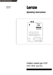
Fig. 3-1
Terminal assignment of the function module PROFIBUS-DP
Note!
The bus system must be terminated at the physically first and last bus device (master or slave)!
3-2
BA8200AUT
EN
1.0
Show/Hide Bookmarks
Automation
PROFIBUS-DP
3.3.2.2
Wiring with a host (PC or PLC)
Basic structure
Specification bus cable
Cable resistance
1
3
3
82 motec
82 vector
+
82ZAFP
2
3
82 motec
82 vector
+
82ZAFP
82 motec
82 vector
+
82ZAFP
2
2
Capacitance per unit
length
≤ 30 nF/km
Loop resistance
< 110 Ω/km
Wire diameter
> 0.64 mm
Wire cross-section
0.34 mm2
Wires
twisted pair, insulated
and screened
£ 1000 m
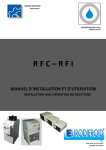
Fig. 3-2
135 - 165 Ω/km
(f = 3 - 20 MHz)
Basic structure of a PROFIBUS-DP network with RS485 cabling without repeater
Elements of the PROFIBUS-DP network
No.
1
2
Element
Host
Bus
us cable
cab e
3
PROFIBUS-DP slave
Note
e.g. PC or PLC with PROFIBUS-DP master interface module
Baud rate [kbit/s]
9.6 - 187.5
500
max. length [m]
1000
400
Lenze controller with function module PROFIBUS-DP (82ZAFP)
1500
200
12000
100
Note!
l The controller has a double basic insulation to VDE 0160. An additional mains insulation is not
required.
3.4
Commissioning of function module
Stop!
l Prior to connecting the mains voltage, check
– the entire wiring for completeness, earth fault and short circuit.
– whether the bus system is terminated at the physically first and last bus device.
l Keep to the switch-on sequence!
BA8200AUT
EN
1.0
3-3
Show/Hide Bookmarks
Automation
PROFIBUS-DP
3.4.1
Initial switch-on
Step
1. Configure master system for the
communication with the function module
PROFIBUS-DP.
Lenze setting
Note
3-6
2. For the first and last bus device only:
– DIP switch = ON ( 3-2)
OFF
Activate bus terminating resistor.
3. Connect mains voltage of the controller and, if
necessary, the external supply of the function
module.
4. Assign a station address to every bus device
under C1509.
The green LED on the function module is
illuminated (visible only on 8200 vector).
3-6)
3
Every bus device has another address. (
5. You can communicate now with the controller.
The yellow LED is flashing when the
PROFIBUS-DP is active.
6. If necessary, adapt the codes to your
application.
See Operating Instructions of the controller
7. Select fieldbus function module as source for
control commands and setpoints: C0005 =
200.
88. Assign
ss g pprocess
ocess ou
output
pu words
o ds (POW)
( O ) of
o thee
master
t via
i C1511 to
t the
th process input
i t words
d
of the controller
controller. ( 3-13)
3 13)
Necessary setting to communicate with the
controllers via fieldbus.
POW1:
POW2:
DRIVECOM control word (DRIVECOM CTRL)
Setpoint1 (NSET1-N1)
POW3:
POW4:
POW5:
POW6:
POW7:
POW8:
Setpoint2 (NSET1-N2)
Additional setpoint (PCTRL1-NADD)
Act. process controller value (PCTRL1-ACT)
Process controller setpoint (PCTRL1-SET1)
reserved (FIF-RESERVED)
Torque setpoint or torque limit value
(MCTRL1-MSET)
POW9:
POW10:
99. Assign
ss g pprocess
ocess ou
output
pu words
o ds oof thee co
controller
oe
PIW1:
t the
to
th process iinputt words
d (PIW) off the
th master
t
PIW2:
via C1510
C1510. ( 3-17)
3 17)
PIW3:
PIW4:
PIW5:
PIW6:
PIW7:
PIW8:
PIW9:
PIW10:
10.Enable process output data: C1512 = 65535.
11.Enable controller via terminal.
12.Select the setpoint.
13.Change to state “READY TO START“:
PWM voltage (MCTRL1-VOLT-ADD)
PWM phase (MCTRL1-PHI-ADD)
DRIVECOM status word (DRIVECOM STAT)
Output frequency with slip (MCTRL1-NOUT+SLIP)
Output frequency without slip (MCTRL1-NOUT)
Apparent motor current (MCTRL1-IMOT)
Act. process controller value (PCTRL1-ACT)
Process controller setpoint (PCTRL1-SET1)
Process controller output (PCTRL1-OUT)
Controller load (MCTRL1-MOUT)
DC-bus voltage (MCTRL1-DCVOLT)
Ramp function generator input (NSET1-RFG1-IN)
Only necessary when C1511 was changed.
X3/28 = HIGH
Master sends setpoint via selected POW.
Master sends DRIVECOM control word = 0000
0000 0111 1110bin (007Ehex).
14.Controller is “READY TO START“.
Master receives DRIVECOM status word = xxxx
xxxx x01x 0001bin.
15.Change to state “OPERATION ENABLED“.
Master sends DRIVECOM control word = 0000
0000 0111 1111bin (007Fhex).
16.The drive is now running.
3-4
BA8200AUT
EN
1.0
Show/Hide Bookmarks
Automation
PROFIBUS-DP
3.4.2
Create complete DRIVECOM compatibility
The DRIVECOM profile 20 is a non-proprietary specification of important parameters and device
performance. The DRIVECOM profile 20 descrives the device control. To achieve complete
DRIVECOM compatibility, deactivate Lenze-specific functions.
Controller
8200 motec
Deactivate function
Automatic DC injection braking
(Auto-DCB)
8200 vector
BA8200AUT
L-C0106 =
L-C2106 =
LL-C4106
C4106 =
L-C6106 =
EN
0,
0,
0,
0
1.0
Drive performance with activated function
Holding time Auto-DCB ≠ 0:
After the holding time has elapsed and at zero speed, the controller
ENABLED” to
changes automatically from the state ”OPERATION
OPERATION ENABLED
state SWITCHED ON”.
If the actual value is higher than 0, it changes automatically to the
state ”OPERATION ENABLED”.
3-5
Show/Hide Bookmarks
Automation
PROFIBUS-DP
3.5
Set up PROFIBUS-DP communication
PROFIBUS-DP transmits two different types of data between the host and the controllers via different
communication channels:
Data
Parameters
In general, the transmission of
e.g. operating parameters, parameters is not as time-critical as the
transmision of process data.
diagnostic information,
motor data
Communication channel used
Parameter channel
l Enables the access to all Lenze codes.
l Parameter changes are normally saved in the controller (observe
C0003).
l If the parameter channel is active, it assigns four words of the
input and output process data (
3-9 )
Process data
e.g. setpoint and actual
values
Process-data channel
l You can control the controller using DRIVECOM process data
( 3-21 ). The host has direct access to the process data. In the
PLC, for instance, the data are directly assigned to the I/O area.
l Process data are transmitted cyclically (constant exchange of
momentary input and output data between host and controllers).
l Process data are not saved in the controller.
Data must be exchanged in the shortest
possible time.Small amounts of data
which are transmitted cyclically.
3.5.1
Configure master system for the communication with the function module
3.5.1.1
Master settings
For the set-up of PROFIBUS-DP, the master needs the device description file LENZ00DA.GSD
supplied on diskette.
Copy LENZ00DA.GSD to the corresponding directory of your set-up software (e.g. to the directory
”GSD” for the COM PROFIBUS software).
3.5.1.2
Addressing of the bus devices (station address)
To address the controllers in the PROFIBUS-DP network, each device gets an address. Every bus
device must have another address.
The address can be set in two ways:
l Setting of the station address via keypad/PC:
– Set the address under C1509 in the controller.
– Valid address range: 3 ¡ 126.
l Setting of the station address by a master (master class 2 only):
– With this method only one PROFIBUS-DP device must be connected. This can be achieved
by a special switch-on sequence.
3.5.1.3
Determine user data length
The PROFIBUS-DP user data length is determined during the DP initialization phase (configuration).
You can configure up to 10 process data words. As an option, you can activate the parameter
channel. If the parameter channel is active, it assigns four words of the input and output process data.
The user data length for the process input data and process output data are identical. They are
selected in the set-up software for the PROFIBUS-DP system via label byte.
3-6
BA8200AUT
EN
1.0
Show/Hide Bookmarks
Automation
PROFIBUS-DP
Possible user data lengths:
1 ... 100 words
o ds process
p ocess data
da a
Label 70hex ... 79hex (112 ... 121)
POW1/PIW1
Byte 1 Byte 2
Parameter
a a e e channel
c a e + 1 ... 100 words
o ds process
p ocess data
da a
label 73hex (115), 70hex ... 79hex (112 ... 121)
...
...
POW10/PIW10
... Byte 19 Byte 20
Parameter channel
Word 1
...
Word 4
POW1/PIW1
...
POW10/PIW10
Byte 1 Byte 2 ... ... Byte 7 Byte 8 Byte 9 Byte 10 ... ... Byte 27 Byte 28
General structure of the label byte
MSB
7
LSB
6
5
4
3
2
1
0
Data length
00 1 byte or 1 word
...
15 16 bytes or 16 words
Input/Output
00 Special label format
01 Input
10 Output
11 Input and output
Length/Format
0 Byte
1 Word
Consistency
0 Byte or word
1 Total length
BA8200AUT
EN
1.0
3-7
Show/Hide Bookmarks
Automation
PROFIBUS-DP
You will find the following configurations in the file LENZ00DA.GSD:
User data length
Use
e gt
Assigned I/O memory
Selection
Se
ect o te
textt in LENZ00DA.GSD
00 GS
[Words]
5
6
7
8
9
10
11
12
13
14
5
6
7
8
9
10
11
12
13
14
1
2
3
4
5
6
7
8
9
10
With
t 4 words
o ds pa
parameter
a ete PAR
+ PCD (1 word I/O)
channel
h
l without
ith t
PAR
+ PCD (2 words I/O)
consistency
PAR
+ PCD (3 words I/O)
PAR
+ PCD (4 words I/O)
PAR
+ PCD (5 words I/O)
PAR
+ PCD (6 words I/O)
PAR
+ PCD (7 words I/O)
PAR
+ PCD (8 words I/O)
PAR
+ PCD (9 words I/O)
PAR
+ PCD (10 words I/O)
With
t 4 words
o ds pa
parameter
a ete PAR (KONS) + PCD (1 word I/O)
channel
h
l with
ith
PAR (KONS) + PCD (2 words I/O)
consistency
PAR (KONS) + PCD (3 words I/O)
PAR (KONS) + PCD (4 words I/O)
PAR (KONS) + PCD (5 words I/O)
PAR (KONS) + PCD (6 words I/O)
PAR (KONS) + PCD (7 words I/O)
PAR (KONS) + PCD (8 words I/O)
PAR (KONS) + PCD (9 words I/O)
PAR (KONS) + PCD (10 words I/O)
Without
t out pa
parameter
a ete
PCD (1 word I/O)
channel
h
l
PCD (2 words I/O)
PCD (3 words I/O)
PCD (4 words I/O)
PCD (5 words I/O)
PCD (6 words I/O)
PCD (7 words I/O)
PCD (8 words I/O)
PCD (9 words I/O)
PCD (10 words I/O)
Label byte 1
[dez]
[hex]
115
73
243
F3
112
113
114
115
116
117
118
119
120
121
70
71
72
73
74
75
76
77
78
79
Label byte 2
[dez]
112
113
114
115
116
117
118
119
120
121
112
113
114
115
116
117
118
119
120
121
[hex]
70
71
72
73
74
75
76
77
78
79
70
71
72
73
74
75
76
77
78
79
-
-
Tip!
Additional label byte
Apart from the configurations in the file LENZ00DA.GSD, the following label bytes are also valid:
l Parameter channel
– 25dec , 37hex (8 bytes without consistency)
– 183dec , B7hex (8 bytes with consistency)
l Process data channel
– 240dec ... 249dec , F0hex ... F9hex (with complete consistency)
Use complete consistency
l We recommend to use only configurations with consistency for the parameter channel to
avoid data conflicts between PROFIBUS-DP master and the CPU of the master system.
l Please note that the different master systems process consistent data in a different way and
consider this in the PROFIBUS-DP application program.
l Comprehensive description of the consistency: ( 6-1)
3-8
BA8200AUT
EN
1.0
Show/Hide Bookmarks
Automation
PROFIBUS-DP
3.5.2
Configure parameter channel
The PROFIBUS-DP parameter channel enables the access to all Lenze codes.
3.5.2.1
Structure of the parameter channel
Byte 1
Service
Byte 2
Subindex
Byte 3
Index
High byte
Byte 51)
Data 4
Byte 4
Index
Low byte
In case of faulty transmission
1)
Byte 61)
Data 3
Byte 71)
Data 2
Byte 81)
Data 1
High Byte 1
Low Byte 1
High Byte 2
Low Byte 2
High Word
Low Word
Double Word
Error 4
Error 3
Error 2
Error 1
Error class
Error code
Additional Code Additional Code
High Byte
Low Byte
Saving in the Motorola format: First the High Byte/High Word, then the Low Byte/Low Word.
Byte
yte 1 Se
Service
ce
Job and
a d response
espo se co
control
o
f the
for
th DP parameter
t
channel.
Bit
Meaning
2|1|0 Job/Service
000 no job
001 Read job
010 Write job
3
Reserved
5|4
Data length
00 1 Byte
01 2 Byte
11 4 Byte
6
Job/Handshake
Indicates a new job.
7
Job/Status
0 Job completed with fault.
1 Job not completed. A fault
occured.
Type of job to the controller
The bits are set only by the master.
Read data from the controller
Write data to the controller
Length of the data in the field data/error.
Is changed by the master for every new
job. The controller copies the bit to its
response message.
Status information from the controller to
the master. Informs the master whether the
job was carried out without faults.
Data in the field Data/Error are interpreted
as error message.
Byte 2 Subindex
Additional addressing to
select subcodes.
For codes without subcodes, byte 2 must be zero, otherwise the job cannot be
completed.
Byte 3 Index High Byte
PROFIBUS-DP
O US
index
de oof thee
d i d LLenze code
desired
d
PROFIBUS-DP
O US
index
de = 24575
5 5 - Lenze
e e code number
u be
Byte 4 Index Low Byte
Byte
yte 5
Data 4 High Byte 1
Error 4 Error class
Byte
yte 6
Data 3 Low Byte 1
Error 3 Error code
Byte
yte 7
Data 2 High Byte 2
Parameter
a a e e value
a ue or
o fault
au information
o a o indicated
d ca ed with invalid
a d access.
access
Byte 1, Bit 7 ”Job/Status” determines the meaning of the data field.
l Data
– Parameter value, which assigns 1 to 4 bytes depending on the data format.
– Strings
g or data blocks cannot be transferred.
l Error
E
– Fault
Fa lt detection (for description see the following table).
table)
Error 2 Additional Code High Byte
Byte
yte 8
Data 1 Low Byte 2
Error 1 Additional Code Low Byte
BA8200AUT
EN
1.0
3-9
Show/Hide Bookmarks
Automation
PROFIBUS-DP
Fault messages in the error field (Data/Error)
3.5.2.2
Byte 5
Byte 6
Error class
0
6
6
6
6
6
6
8
8
8
8
8
Error code
0
3
5
5
5
7
8
0
0
0
0
0
Byte 7
Byte 8
Additional code [hex]
00
00
00
00
00
10
00
11
00
12
00
00
00
00
00
21
00
22
00
30
00
40
00
20
Meaning
Meaning
No fault
No access permission
Inadmissible job parameter
Invalid subindex
Data too long
Object does not exist
Data types are not identical
Cannot be executed because of local control
Cannot be executed because of unit status
Leave value range
Collision with other values
Service cannot be executed currently
Access to Lenze parameters
Lenze parameters are addressed via Lenze codes. For Lenze parameters with the assigned value
ranges, please refer to the code table of the controller.
Lenze codes
In this description, Lenze codes are identified by
„L-Cxxxx“, to avoid confusion with the
PROFIBUS-DP index (e.g. L-C0001 for Lenze Code
C0001).
Lenze parameters
Lenze parameters primarily represented in the
fixed-point format (data type Integer32) with four
decimal codes.
Lenze
e e pa
parameter
a ete
sets
t
3-10
Addressing
l Addressing of Lenze codes via offset:
– PROFIBUS-DP index = 24575 - LENZE_CODENR
– PROFIBUS-DP indexhex = 5FFFhex - LENZE_CODENRhex
l Example for L-C0001 (operating mode):
– PROFIBUS-DP index = 24574 (= 24575 - 1)
– PROFIBUS-DP indexhex = 5FFEhex (= 5FFFhex - 1hex)
l Multiply desired parameter value with 10000.
l Example: Set L-C0039 (JOG) = 150.4 Hz:
– 150.4 x 10000 = 1504000dec (0016F300hex)
Thee four
ou parameter
pa a e e sets
se s can
ca be addressed
add essed directly
d ec y O
Offset
set
Parameter
a a ete set
Example:
with
ith PROFIBUS
PROFIBUS-DP
DP via
i code
d offsets:
ff t
Address of C0011
Use offset 0 for parameters which occur
occ r only once!
0
1
11
(Marked with “*”in the code tables.)
tables )
2000
2
2011
4000
3
4011
6000
4
6011
BA8200AUT
EN
1.0
Show/Hide Bookmarks
Automation
PROFIBUS-DP
3.5.2.3
Read job to the controller
Example
Read heatsink temperature C0061 (= 43 C) from controller.
1. Determine the user data range of the controller: i. e.
determine the location of the DP user data in the host.
2. Enter address of the desired parameter in the field ”Index and Byte 2 =
subindex“.
Byte 3 =
Byte 4 =
3. Specify job
Byte 1 =
4. Check, whether the bit ”job/handshake“ is the same for the
DP input data and the DP output data. If the bit
”job/handshake“ is the same, the response has been
received. It is useful to monitor the communication time.
5. Check whether the bit ”Job/Status“ is set.
– Not set = the field ”Data/Error“ contains the desired
parameter value.
– Set = Read job not completed successfully, the field
”Data/Error“ contains error information.
Byte 5 =
Byte 6 =
Byte 7 =
Byte 8 =
0
5Fhex
C2hex
0xxx 0001
Subindex = 0, because C0061 has no subcode.
Index = 24575 - Code no.
Index = 24575 - 61 = 24514 = 5FC2hex
Bit 0-2 = 001 (1 = Read job)
Change bit 6 ”Job/Handshake“
00
06hex
8Fhex
B0hex
00 06 8F B0hex = 430000dec
430000/10000 = 43 (43 °C heat sink temperature)
Response to drive
Byte 1
Service
Byte 2
Subindex
0xxx 0001
0
Byte 3
Index
High byte
5F
Byte 4
Index
Low byte
C2
Byte 5
Data 4
Byte 6
Data 3
Byte 7
Data 2
Byte 8
Data 1
00
00
00
00
Byte 5
Data 4
Byte 6
Data 3
Byte 7
Data 2
Byte 8
Data 1
00
06
8F
B0
Response of the drive when completed successfully
Byte 1
Service
Byte 2
Subindex
0x11 000x
0
Byte 3
Index
High byte
5F
BA8200AUT
Byte 4
Index
Low byte
C2
EN
1.0
3-11
Show/Hide Bookmarks
Automation
PROFIBUS-DP
3.5.2.4
Write job to the controller
Example
Change acceleration time C0012 of the controller to 20 s.
1. Determine the user data range of the controller: i. e.
determine the location of the DP user data in the host.
2. Enter address of the desired parameter in the field ”Index and Byte 2 =
subindex“.
Byte 3 =
Byte 4 =
3. Calculate data value and enter.
Byte 5 =
Byte 6 =
Byte 7 =
Byte 8 =
4. Specify job
0
5F
F3
00
03
0D
40
Subindex = 0, because C0012 has no subcode.
Index = 24575 - Code no.
Index = 24575 - 12 = 24563 = 5FF3hex
20 s x 10000 = 200000dec = 00 03 0D 40hex
Byte 1 = 0x11 0010 Bit 0-2 = 010 (1 = Write job)
Bit 4-5 = 11 (4 Byte data)
Change Bit 6 ”Job/Handshake”
5. Check, whether the bit ”job/handshake“ is the same for the
DP input data and the DP output data. If the bit
”job/handshake“ is the same, the response has been
received. It is useful to monitor the communication time.
6. Check whether the bit ”Job/Status“ is set.
– Not set = Write job completed without fault.
– Set = Write job not completed successfully, the field
”Data/Error“ contains error information.
Response to drive
Byte 1
Service
Byte 2
Subindex
0x11 0010
0
Byte 3
Index
High byte
5F
Byte 4
Index
Low byte
F3
Byte 5
Data 4
Byte 6
Data 3
Byte 7
Data 2
Byte 8
Data 1
00
03
0D
40
Byte 5
Data 4
Byte 6
Data 3
Byte 7
Data 2
Byte 8
Data 1
00
00
00
00
Response of the drive when completed successfully
3-12
Byte 1
Service
Byte 2
Subindex
0xxx 00x0
0
Byte 3
Index
High byte
5F
Byte 4
Index
Low byte
F3
BA8200AUT
EN
1.0
Show/Hide Bookmarks
Automation
PROFIBUS-DP
3.5.3
Configure process data channel
Assign the max. 10 process data words of PROFIBUS-DP to the process data words of the controller
via the free configuration of the process data. Make the assignments in codes C1511 (process output
data) and C1510 (process input data).
From the position of the master:
l The master sends process output data in max. 10 process data output words (POW) to the
bus device.
l The master receives process input data in max. 10 process data input words (PIW) from the
bus device.
3.5.3.1
Configure process output data
Code
No.
Name
Possible settings
IMPORTANT
Lenze
Standardization
Selection
C1511 Configuration
process output data
master
1
2
3
4
5
6
Parameter
channel
Assigns process data output words of the master
to bit control commands or setpoints of the
controller.
Modification of C1511 automatically inhibits
process output data to ensure data
consistency.
Enable again under C1512.
POW1
POW2
POW3
POW4
POW5
POW6
17
3
4
5
6
7
1
2
3
4
5
6
FIF control word 1 (FIF-CTRL1)
FIF control word 2 (FIF-CTRL2)
Setpoint 1 (NSET1-N1)
Setpoint 2 (NSET1-N2)
Additional setpoint (PCTRL1-NADD)
Act. process controller value (PCTRL1-ACT)
16 Bit
16 Bit
±24000
±24000
±24000
±24000
7 POW7
8 POW8
9 POW9
8
9
10
7
8
9
Process controller setpoint (PCTRL1-SET1)
Reserved
Torque setpoint or torque limit value
(MCTRL1-MSET)
±24000 ≡ ±480 Hz
C0138
214 ≡ 100 % rated motor torque
C0047
10 POW10
11
10
11
12
13
14
15
16
17
0
PWM voltage (MCTRL1-VOLT-ADD)
PWM phase (MCTRL1-PHI-ADD)
Reserved
FIF-IN.W1
FIF-IN.W2
FIF-IN.W3
FIF-IN.W4
DRIVECOM control word (DRIVECOM-CTRL)
{1}
65535
65535 = enable all
POW10 POW9 ...
POW3 POW2 POW1
29
28
...
22
21
20
O y for
Only
o spec
special
a app
applications.
cat o s Modifications
od cat o s
only
l when
h agreed
d on bby LLenze!!
C1512 Enable process
output
p data
≡ ±480 Hz
≡ ±480 Hz
≡ ±480 Hz
≡ ±480 Hz
C0046
C0044
C0049
C0051 when
C0238 = 1, 2
16 bit or 0 ... 65535
16 bit or 0 ... 65535
0 ... 65535
0 ... 65535
16 bit
The decimal value of the bit settings enables any
combinations of the process
output
p
p words.
l 0 = Inhibit
I hibit output
t t word
d
l 1 = Enable output word
The assignment of the max. 10 process data output words (POW) of the master can be freely
configured to bit control commands or setpoints:
l To activate the DRIVECOM control, assign the DRIVECOM control word (C1511/x = 17) to a
POW.
– The DRIVECOM control word is mapped to the FIF control word 1.
– The controller complies with the DRIVECOM status machine ( 3-21) .
l Use the FIF control words to set up an extended device control. ( 3-16) .
l The process output data are inhibited automatically when C1511 is modified to ensure data
consistency. Under C1512, you can enable individual or all POWs.
BA8200AUT
EN
1.0
3-13
Show/Hide Bookmarks
Automation
PROFIBUS-DP
FIF-IN
FIF-CTRL.B0
FIF-CTRL.B1
FIF-CTRL.B2
Byte 1
DRIVECOM
CTRL
Byte 2
C1511/x = 1
QSP
DCTRL
FIF-CTRL.B9
CINH
DCTRL
FIF-CTRL.B10
TRIP-SET
FIF-CTRL.B11
TRIP-RESET
FIF-CTRL.B3
FIF-CTRL1
C1511/x = 17
FIF-CTRL.B4
…
FIF-CTRL.B8
C0410/x
200
FIF-CTRL.B12
Internal digital signals
…
Byte 3
C1511/x = 6
C1511/x = 7
C1511/x = 9
C1511/x = 10
C1511/x = 11
C1511/x = 13
C1511/x = 14
C1511/x = 15
C1511/x = 16
Fig. 3-3
3-14
…
FIF-CTRL.B30
FIF-CTRL.B31
Byte 5, 6
C1511/x = 5
FIF-CTRL.B17
FIF-NSET1-N1
Byte 7, 8
C1511/1
C1511/2
C1511/3
C1511/4
C1511/5
C1511/6
C1511/7
C1511/8
C1511/9
C1511/10
C1511/x = 4
FIF-CTRL.B16
16 Bit
16 Bit
FIF-NSET1-N2
16 Bit
FIF-PCTRL1-NADD
FIF-PCTRL1-ACT
16 Bit
FIF-PCTRL1-SET1
16 Bit
FIF-RESERVED
16 Bit
C0412/x
200
Internal analog signals
FIF-MCTRL1-MSET
16 Bit
FIF-IN.W4 FIF-IN.W3 FIF-IN.W2 FIF-IN.W1
PAW1
PAW2
PAW3
PAW4
PAW5
PAW6
PAW7
PAW8
PAW9
PAW10
C1511/x = 3
Byte 31, 32 Byte 29, 30 Byte 27, 28 Byte 25, 26 Byte 23, 24 Byte 21, 22 Byte 19, 20 Byte 17, 18 Byte 15, 16 Byte 13, 14 Byte 11, 12 Byte 9, 10
PROFIBUS
Master
Byte 4
C1511/x = 2
FIF-CTRL2
FIF-CTRL.B15
16 Bit
FIF-MCTRL1-VOLT-ADD
16 Bit
FIF-MCTRL1-PHI-ADD
16 Bit
FIF-RESERVED
FIF-IN.W1. B0 … FIF-IN.W1.B15
16 Bit
FIF-IN.W1
FIF-IN.W2. B0 … FIF-IN.W2.B15
16 Bit
FIF-IN.W2
C0415/x
C0417/x
C0418/x
Digital outputs
Output of digital signals on bus
FIF-IN.W3
16 Bit
C0419/x
C0421/x
Analog outputs
Output of analog outputs on bus
FIF-IN.W4
16 Bit
Free configuration of the 10 process output words of the PROFIBUS-DP
BA8200AUT
EN
1.0
Show/Hide Bookmarks
Automation
PROFIBUS-DP
Structure of the parameter ”DRIVECOM control word” (DRIVECOM-CTRL):
Bit
0
Meaning
Command ”Switch on”
0 Command ”Stop” active
1 Command ”Switch on” active
1
Command ”Inhibit voltage”
0 Command ”Inhibit voltage” active
1 Command ”Inhibit voltage” not active
2
Command ”Quick stop”
0 Command ”Quick stop” activated
1 Command ”Quick stop” not active
3
Command ”Enable operation”
0 Command ”Inhibit operation” active
1 Command ”Enable operation” active
4
Command ”Inhibit ramp generator”
Inhibit the ramp generator (NSET1-RFG1). The quick stop function is released; the drive remains in its status.
Mapping to FIF control word 1 (FIF-CTRL1), bit 3 negated (FIF-CTRL1-QSP)
0 Inhibit ramp generator active
1 Inhibit ramp generator not activated
5
Command ”Stop ramp generator”
Output of the ramp generator (NSET1-RFG1) is ”frozen”; the drive remains in its status.
Mapping to FIF control word 1 (FIF-CTRL1), bit 4 negated (NSET1-RFG1-STOP)
0 0 = RFG stop
1 1 = RFG stop not active
6
Command ”Ramp generator zero”
Set input of ramp generator (NSET1-RFG1) to zero. ⇒ Controlled deceleration along the ramp set under C0013; the drive
remains in its state.
Mapping to FIF control word 1 (FIF-CTRL1), bit 5 negated (NSET1-RFG1-0)
0 0 = RFG zero
1 1 = RFG zero not active
7
TRIP reset
Fault reset (TRIP).
0 ⇒ 1 Bit change causes TRIP reset
8
DRIVECOM reserved
9
DRIVECOM reserved
10
DRIVECOM reserved
11
Mapping to FIF control word 1 (FIF-CTRL1), bit 10 (FIF-CTRL1-TRIP-SET)
12
Mapping to FIF control word 1 (FIF-CTRL1), bit 12 (DCTRL1-PAR2/4)
13
Mapping to FIF control word 1 (FIF-CTRL1), bit 13 (DCTRL1-PAR-3/4)
14
Mapping to FIF control word 1 (FIF-CTRL1), bit 14 (MCTRL1-DCB)
15
Not assigned
BA8200AUT
EN
1.0
3-15
Show/Hide Bookmarks
Automation
PROFIBUS-DP
Structure of parameter FIF control word (FIF-CTRLx)
FIF control word 1 (FIF-CTRL1)
FIF control word 2 (FIF-CTRL2)
Bit
Assignment
Bit
Assignment
1|0
JOG values
(NSET1-JOG2/3 | NSET1-JOG1/3)
0
Manual/Remote change-over (DCTRL1-H/Re)
00
001
10
11
C0046 active
JOG1 (C0037)
JOG
(C003 ) active
ac e
JOG2 (C0038) active
JOG3 (C0039) active
0 not active
1 active
Switch-off the integral action component of the
process controller (PCTRL1-I-OFF)
1
0 not active
1 active
2
Actual direction of rotation (DCTRL1-CW/CCW)
2
0 not inverted
1 inverted
3
Switch-off the process controller (PCTRL1-OFF)
0 not active
1 active
3
Quick stop (FIF-CTRL1-QSP)
Reserved
ese ed
0 not active
1 active (deceleration along QSP ramp C0105)
4
Stop ramp function generator (NSET1-RFG1-STOP)
4
0 not active
1 active
5
Stop the process controller (PCTRL1-STOP)
0 not active
1 active
Ramp function generator input = 0 (NSET1-RFG1-0) 5
0 not active
1 active (deceleration to C0013)
6
UP function of motor potentiometer (MPOT1-UP)
6
0 not active
1 active
7
CW rotation/quick stop (DCTRL1-CW/QSP)
0 not active
1 active
CCW rotation/quick stop (DCTRL1-CCW/QSP)
0 not active
1 active
DOWN function of motor potentiometer
(MPOT1-DOWN)
7
0 not active
1 active
X3/E1 is digital frequency input (DFIN1-ON)
0 not active
1 active
8
Reserved
8
Reserved
9
Controller inhibit (FIF-CTRL1-CINH)
9
Reserved
0 Controller enabled
1 Controller inhibited
10
External fault (FIF-CTRL1-TRIP-SET)
10
Reserved
11
Fault reset (FIF-CTRL1-TRIP-RESET)
11
Reserved
ese ed
Parameter set changeover
(DCTRL1-PAR3/4 | DCTRL1-PAR2/4)
12
Reserved
PAR1
PAR2
PAR3
PAR4
13
Reserved
DC injection brake (MTCRL1-DCB)
14
Reserved
ese ed
15
Reserved
0 ⇒ 1 Bit change causes TRIP reset
13|12
00
01
10
11
14
0 not active
1 active
15
3-16
Reserved
BA8200AUT
EN
1.0
Show/Hide Bookmarks
Automation
PROFIBUS-DP
3.5.3.2
Configure process input data
Code
No.
Name
Possible settings
IMPORTANT
Lenze
Standardisation
Selection
C1510 Configuration
process input data
master
Parameter
channel
Assigns status information or actual values of the
controller to the process data input words of the
master.
1 PIW1
2 PIW2
3 PIW3
18
3
4
1
2
3
FIF control word 1 (FIF-STAT1)
FIF status word 2 (FIF-STAT2)
Output frequency with slip (MCTRL1-NOUT+SLIP)
16 Bit
16 Bit
±24000 ≡ ±480 Hz
C0051 when
C0238 = 2
4 PIW4
5 PIW5
5
6
4
5
Output frequency without slip (MCTRL1-NOUT)
Apparent motor current (MCTRL1-IMOT)
±24000 ≡ ±480 Hz
214 ≡ 100 % rated controller
current
C0050
C0054
6 PIW6
7
6
Act. process controller value (PCTRL1-ACT)
±24000 ≡ ±480 Hz
C0051 when
C0238 = 0, 1
7 PIW7
8 PIW8
9 PIW9
8
9
10
7
8
9
Process controller setpoint (PCTRL1-SET)
Process controller output (PCTRL1-OUT)
Controller load (MCTRL1-MOUT)
±24000 ≡ ±480 Hz
±24000 ≡ ±480 Hz
±214 ≡ ±100 % rated motor
torque
10 PIW10
11
10
DC-bus voltage (MCTRL1-DCVOLT)
11
12
13
14
15
16
17
18
1ph: 960 ≡ DC 400 V
3ph: 975 ≡ DC 800 V
Ramp function generator input (NSET1-RFG1-IN)
±24000 ≡ ±480 Hz
Ramp function generator output (NSET1-RFG1-OUT) ±24000 ≡ ±480 Hz
jFIF-OUT.W1
16 Bit or 0 ... 65535
FIF-OUT.W2
16 Bit or 0 ... 65535
FIF-OUT.W3
0 ... 65535
FIF-OUT.W4
0 ... 65535
DRIVECOM control word (DRIVECOM-CTRL)
16 Bit
DRIVECOM status word (DRIVECOM-STAT)
16 Bit
C0053
The bit status information or the actual values of the controllers can be freely assigned to the max.
10 process data input words (PIW) of the master.
l To call DRIVECOM-conform status information, assign the DRIVECOM status word to a PIW
(C1511/x = 18).
– The FIF status word 1 is mapped to the DRIVECOM status word.
l You can call enhanced status information using the FIF status words.
BA8200AUT
EN
1.0
3-20)
(
3-17
Show/Hide Bookmarks
Automation
PROFIBUS-DP
FIF-OUT
…
FIF-STAT.B31
PCTRL1-ACT
PCTRL1-SET
PCTRL1-OUT
MCTRL1-MOUT
MCTRL1-DCVOLT
PCTRL1-RFG1-IN
NSET1-NOUT
16 Bit
C1510/x = 4
Byte 9, 10 Byte 11, 12 Byte 13, 14 Byte 15, 16 Byte 17, 18 Byte 19, 20 Byte 21, 22 Byte 23, 24
MCTRL1-IMOT
C1510/x = 3
Byte 7, 8
MCTRL1-NOUT+SLIP
16 Bit
Byte 5, 6
MCTRL1-NOUT
C1510/x = 2
Byte 4
FIF-STAT.B30
FIF-STAT2
FIF-STAT.B17
Byte 3
FIF-STAT.B16
C1510/x = 1
Byte 2
FIF-STAT.B15
C1510/x = 18
16 Bit
16 Bit
16 Bit
16 Bit
16 Bit
16 Bit
16 Bit
16 Bit
C1510/x = 5
C1510/x = 6
C1510/x = 7
C1510/x = 8
C1510/x = 9
C1510/x = 10
C1510/x = 11
C1510/x = 12
STAT1
PEW1
PEW2
PEW3
PEW4
PEW5
PEW6
PEW7
PEW8
PEW9
PEW10
FIF-OUT.W1.B0
FIF-OUT.W1.B1
C1510/x = 13
FIF-OUT.W2
Byte 27, 28
C1510/x = 14
FIF-OUT.W3 FIF-OUT.W4
Byte 29, 30 Byte 31, 32
…
Byte 25, 26
STAT1.B0
STAT1.B1
STAT1.B2
STAT1.B3
STAT1.B4
STAT1.B5
STAT1.B6
STAT1.B7
STAT1.B8
STAT1.B9
STAT1.B10
STAT1.B11
STAT1.B12
STAT1.B13
STAT1.B14
STAT1.B15
FIF-OUT.W1
C0417/1
DCTRL1-IMP
C0417/3
C0417/4
C0417/5
C0417/6
DCTRL1-NOUT=0
DCTRL1-CINH
DCTRL1-STAT*1
DCTRL1-STAT*2
DCTRL1-STAT*4
DCTRL1-STAT*8
DCTRL1-OH-WARN
DCTRL1-OV
C0417/15
C0417/16
C1510/1
C1510/2
C1510/3
C1510/4
C1510/5
C1510/6
C1510/7
C1510/8
C1510/9
C1510/10
PROFIBUS
Master
…
FIF-STAT.B14
FIF-STAT1
FIF-STAT.B2
DRIVECOM
STAT
Byte1
FIF-STAT.B1
FIF-OUT.W1.B14
FIF-OUT.W1.B15
16 Bit
C0421/3
STAT2
C0418/1
C0418/2
…
C0418/15
C0418/16
Fig. 3-4
3-18
STAT2.B0
STAT2.B1
STAT2.B14
STAT2.B15
FIF-OUT.W2.B0
FIF-OUT.W2.B1
…
FIF-OUT.W2.B14
FIF-OUT.W2.B15
C0421/4
16 Bit
C0421/5
16 Bit
C0421/6
16 Bit
C1510/x = 15
C1510/x = 16
Free configuration of the 10 process input words of the PROFIBUS-DP
BA8200AUT
EN
1.0
Show/Hide Bookmarks
Automation
PROFIBUS-DP
Parameter structure “DRIVECOM status word“ (DRIVECOM-STAT):
Bit
0
Meaning
Controller status ”READY TO START”
0 Status less than ”READY TO START”
1 Status at least ”READY TO START”
1
Controller status ”READY TO START”
0 Status less than ”SWITCHED ON”
1 Status at least ”SWITCHED ON”
2
Controller status ”OPERATION ENABLED”
0 Status less than ”OPERATION ENABLED”
1 Status at least ”OPERATION ENABLED”
3
Controller status ”FAULT”
0 no fault (TRIP)
1 Fault (TRIP) occurred
4
Status command ”Inhibit voltage”
0 Command
1 No command
5
Status command ”Quick stop”
0 Command
1 No command
6
Controller status ”SWITCH-ON INHIBIT”
0 Status not ”SWITCH-ON INHIBIT”
1 Status ”SWITCH-ON INHIBIT”
7
Collective warning
0 No warning
1 Warning (overheat)
8
Collective message
Automatic setting and resetting of pulse inhibit in the controller status ”OPERATION ENABLED”.
Possible causes: Undervoltage, overvoltage or overcurrent.
0 No message
1 Message IMP active
9
Bus access authorization
1 always
10
Status speed/change difference
0 RFGon
HLGoff
1 RFGon = RFGoff
11
Status DRIVECOM speed limitation
0 always
12
Mapping of FIF status word 1 (FIF-STAT1), bit 0 (DCTRL1-PAR-B0)
13
Mapping of FIF status word 2 (FIFSTAT2), bit 0 (DCTRL1-PAR-B1)
14
Mapping of FIF status word 1 (FIFSTAT1), bit 2 (MCTRL1-IMAX)
15
Mapping of FIF status word 1 (FIF-STAT1), bit 5 (PCTRL1-QMIN)
BA8200AUT
EN
1.0
3-19
Show/Hide Bookmarks
Automation
PROFIBUS-DP
Structure of the parameter FIF status word (FIF-STATx)
FIF status word 1 (FIF-STAT1)
FIF status word 2 (FIF-STAT2)
Bit
0
Bit
0
1
2
3
4
Assignment
Momentary parameter set bit 0 (DCTRL1-PAR-B0)
0 Parameter set 1 or 3 active
1 Parameter set 2 or 4 active
Pulse inhibit (DCTRL1-IMP)
0 Power outputs enabled
1 Power outputs inhibited
Imax limit (MCTRL1-IMAX)
(If C0014 = -5-: torque setpoint)
0 not reached
1 reached
Output frequency = Frequency setpoint
(DCTRL1-RFG1=NOUT)
0 false
1 true
Ramp function generator input 1 = ramp function
generator output 1 (NSET1-RFG1-I=O)
5
0 false
1 true
Qmin threshold (PCTRL1-QMIN)
6
0 not reached
1 reached
Output frequency = 0 (DCTRL1-NOUT=0)
0
1
1
0
1
2
3
4
5
0 false
1 true
7
Controller inhibit (DCTRL1-CINH)
0 Controller enabled
1 Controller inhibited
11|10|9|8 Controller status (DCTRL1-STAT*1 ... DCTRL1-STAT*8)
0000 Controller initialization
0001 S
Switch-on
000
c o inhibit
b
0011 Operation inhibited
0100 Flying-restart
Fl i
t t circuit
i it active
ti
0101 DC-injection brake active
0110 Operation enabled
0111 Message active
1000 Active fault
6
7
8
9
10
11
12
13
14
15
3-20
Heat warning (DCTRL1-OH-WARN)
0 No warning
1 ϑmax - 10 C reached
DC-bus overvoltage (DCTRL1-OV)
0 No overvoltage
1 Overvoltage
Direction of rotation (DCTRL1-CCW)
12
13
14
0 CW rotation
1 CCW rotation
Ready for operation (DCTRL1-RDY)
0 Not ready for operation (fault)
1 Ready for operation (no fault)
15
BA8200AUT
EN
Assignment
Momentary parameter set bit 1 (DCTRL1-PAR-B1)
Parameter set 1 or 2 active
Parameter set 3 or 4 active
TRIP or Qmin or pulse inhibit active
(DCTRL1-TRIP-QMIN-IMP)
false
true
PTC warning active (DCTRL1-PTC-WARN)
0 false
1 true
C0054 < C0156 (DCTRL1-IMOT<ILIM)
0 false
1 true
C0054 < C0156 and Qmin threshold reached
(DCTRL1-(IMOT<ILIM)-QMIN)
0 false
1 true
C0054 < C0156 and NSET1-RFG1-I=O
(DCTRL1-(IMOT<ILIM)-RFG-I=O)
0 false
1 true
LP1 warning (fault in the motor phase) active
(DCTRL1-LP1-WARN)
0 false
1 true
f < fmin (NSET1-C0010...C0011)
0 false
1 true
TRIP active (DCTRL1-TRIP)
0 false
1 true
Motor is running (DCTRL1-RUN)
0 false
1 true
Motor running clockwise (DCTRL1-RUN-CW)
0 false
1 true
Motor running counterclockwise (DCTRL1-RUN-CCW)
0 false
1 true
Reserved
Reserved
C0054 > C0156 and NSET1-RFG1-I=0
(DCTRL1-(IMOT>ILIM)-RFG-I=O)
0 false
1 true
Reserved
1.0
Show/Hide Bookmarks
Automation
PROFIBUS-DP
3.5.3.3
The DRIVECOM status machine
FAULT REACTION ACTIVE
Switch on controller
Status word xxxx xxxx x0xx 1111
automaticallly when fault reaction completed
l Commands in the DRIVECOM
NOT READY TO SWITCH ON
parameter ”Control word” can
change the controller status. These
commands are marked by arrows in
the diagram.
13
Fault was recognized
Example:
Status information via parameter ”status word” (index 6041hex) bit 15 ... bit 0 (binary)
The fieldbus function module supplies
the control information via the control
word.
l The controllers have standardized
controller states according to
DRIVECOM profile 20.
l The information about the momentary
controller status are saved in the
DRIVECOM parameter ”Status word”.
Fault
Status word xxxx xxxx x0xx 0000
Status word xxxx xxxx x0xx 1000
automatically when
initializing is completed
14
Reset fault
xxxx xxxx 0xxx xxxx
xxxx xxxx 1xxx xxxx
SWITCH ON INHIBIT
Status word xxxx xxxx x0xx 0000
9
Inhibit voltage
xxxx xxxx xxxx xx0x
2
Stop
xxxx xxxx xxxx
x110
10
12
Inhibit voltage
xxxx xxxx xxxx xx0x
Inhibit voltage xxxx xxxx
xxxx xx01
or
quick stop completed
Quick stop
xxxx xxxx xxxx x01x
READY TO SWITCH ON
Status word xxxx xxxx x01x 0001
7
8
3
6
Standstill
Switch on
xxxx xxxx xxxx
Stop
xxxx xxxx xxxx
x110
xxxx xxxx xxxx x110
x111
SWITCHED ON
Status word xxxx xxxx x01x 0011
4
5
Operation enable
xxxx xxxx xxxx 1111
and actual value <> 0*
Operation inhibit
xxxx xxxx xxxx 0111 or
actual value = 0*
OPERATION ENABLED
QUICK STOP ACTIVE
Status word xxxx xxxx x01x 0111
Status word xxxx xxxx x01x 0111
11
Quick stop
xxxx xxxx xxxx x01x
Inhibit RFG is mapped to
quick stop
BA8200AUT
EN
1.0
Note:
* = valid only with active Auto-DCB
(L-C0106, L-C2106, L-C4106, L-C6106 <> 0)
3-21
Show/Hide Bookmarks
Automation
PROFIBUS-DP
Bit control commands
The bit control commands of the control word depend on other bit
settings.
The command is executed only with the following bit patterns:
Bits of the control word
Command
Stop
Switch on
Operation enable
Inhibit operation
Voltage inhibit
Quick stop
Fault reset
Meaning
From different controller states Õ ”READY TO START”
Transition Õ ”SWITCHED ON”
Transition Õ”OPERATION ENABLED”
The controller inhibit is deactivated.
Transition Õ ”SWITCHED ON”
The controller inhibit is activated.
Transition Õ ”SWITCH ON INHIBIT”
The controller inhibit is activated.
Transition Õ ”SWITCH ON INHIBIT”
If the drive was enabled Õ controlled deceleration along
the Lenze quick stop ramp.
Acknowledge fault.
If the fault is removed, automatically Õ ”SWITCH ON
INHIBIT”
Note
7
x
x
x
6
x
x
x
5
x
x
x
4
x
x
x
3
x
x
1
2
1
1
1
1
1
1
1
0
0
1
1
x
x
x
x
0
1
1
1
x
x
x
x
x
x
0
x
x
x
x
x
x
0
1
x
0 Õ1
x
x
x
x
x
x
x
1 Bit se
set
0 Bit not
set
x Any bit
Fault reset
RFG-zero
RFG-stop
RFG inhibit
Operation enable
Quick stop
Voltage inhibit
Switch on
The current controller status is unambiguously coded in bits 0 to 6 of
the status word:
Status bits
Bits of the status word
Note
Unit status
NOT READY TO SWITCH ON
Meaning
Controller is being initialized and is not yet ready to
operate.
After initialization automatically Õ ”READY TO START”
6
0
5
x
4
x
3
0
2
0
1
0
0
0
SWITCH ON INHIBIT
Controller inhibited (CINH).
Waiting for ”Stop” command.
Controller inhibited (CINH).
Waiting for ”Switch on” command.
Controller inhibited (CINH).
Waiting for ”Enable operation” command.
Controller enabled (CINH).
Pulse inhibit can be set automatically.
Fault (TRIP) was recognized, a fault response initiated.
Then, automatically Õ ”TRIP”
Controller is in the status ”FAULT”
Command ”Quick stop” was sent in the controller status
”Operation enabled”. Õ Controlled deceleration along the
quick stop ramp
After deceleration automatically Õ ”SWITCH ON INHIBIT”
1
x
x
0
0
0
0
0
1
x
0
0
0
1
0
1
x
0
0
1
1
0
1
x
0
1
1
1
0
x
x
1
1
1
1
0
0
x
0
x
x
1
0
0
1
0
1
0
1
READY TO SWITCH ON
SWITCHED ON
OPERATION ENABLED
FAULT REACTION ACTIVE
FAULT
QUICK STOP ACTIVE
1 Bit set
0 Bit not set
x Any bit
Switch-on inhibit
Quick stop
Voltage inhibit
Fault
Operation enabled
Switched on
Ready to switch on
3-22
BA8200AUT
EN
1.0
Show/Hide Bookmarks
Automation
PROFIBUS-DP
3.6
Troubleshooting and fault elimination
Two LEDs on the function module indicate the status:
Blinking
Green LED
Yellow LED
The initialization between function module and Telegram receipt
controller has not yet been carried out.
On
Function module is connected to voltage
supply, no fault.
-
Off
Function module is not connected to voltage
supply.
No telegram receipt
Fault
Possible cause
PROFIBUS-DP
O US
master
as e indicates
d ca es bus Short circuit/Wire breakage
error andd yellow
ll LED on the
h function
f
i
Bus termination not switched on
module is off
PROFIBUS-DP master indicates bus
error and yellow LED on the function
module is blinking
Drivee ca
cannot
o be eenabled
ab ed
Remedy
Check PROFIBUS-DP wiring
Connected the bus terminating resistor to the last bus
device. (
3-2 )
Incorrect station address in C1509
Incorrect PROFIBUS-DP configuration data
Set correct station address. (
3-6 )
Check the configuration data sent by the master under
C1526.
Allowed configuration data:
3-6
No enable via control word
Controller inhibit active via terminal
No setpoint entered
Send 007Fhex
X3/28 = HIGH (+12 ... +30 V)
C0412/1 =200 (setpoint source PROFIBUS-DP) must be
set
Assign process output data to setpoint under C1511
BA8200AUT
EN
1.0
3-23
Show/Hide Bookmarks
Automation
PROFIBUS-DP
3.7
Code table function module PROFIBUS-DP
How to read the code table:
Column
Code
Abbreviation
Cxxxx
1
2
Cxxxx*
Name
Lenze
Selection
Brief, important explanations.
Indicates where to find more detailed information.
Page x
Code
No.
Name of the code
Lenze setting (value set at delivery or after overwriting of C0002 with Lenze setting).
99 Min. value
{Steps/unit}
Max. value
{1 %}
1
IMPORTANT
Meaning
l Thee pa
parameter
a e e value
a ue oof thee code ca
can be de
defined
ed ddifferent
e e for
o
Code Cxxxx
each
h parameter
t set.
t
Subcode 1 of Cxxxx
Subcode 2 of Cxxxx
The parameter value of the code is the same in all parameter sets.
Name
Possible settings
IMPORTANT
Lenze
Standardization
Selection
Parameter
channel
C1500 Software
identification
Output as a string: 82SAFP0B_xy000
C1502 Software
identification
Output as a string in 4 parts à 4 characters
1
...
4
C1501
Part 1
...
Part 4
Software
generation date
Output as a string: mmm tt jjjj hh:mm
Output as a string in 4 parts à 4 characters
C1503 Software
generation date
1
...
4
C1509
3-24
Part 1
...
Part 4
PROFIBUS-DP
station address
3
3
{1}
BA8200AUT
126 For a unambiguous identification, every bus
device must have another station address.
EN
1.0
3-6
Show/Hide Bookmarks
Automation
PROFIBUS-DP
Code
No.
Name
C1510 Configuration
process input data
master
1 PIW1
2 PIW2
3 PIW3
Possible settings
IMPORTANT
Lenze
Standardization
Selection
Parameter
channel
Assigns status information or actual values of
the controller to the process data input words
of the master.
16 Bit
16 Bit
±24000 ≡ ±480 Hz
C0051 when
C0238 = 2
18
3
4
1
2
3
FIF status word 1 (FIF-STAT1)
FIF status word 2 (FIF-STAT2)
Output frequency with slip
(MCTRL1-NOUT+SLIP)
4 PIW4
5 PIW5
5
6
4
5
Output frequency without slip (MCTRL1-NOUT)
Apparent motor current (MCTRL1-IMOT)
±24000 ≡ ±480 Hz
214 ≡ 100 % rated controller
current
C0050
C0054
6 PIW6
7
6
Act. process controller value (PCTRL1-ACT)
±24000 ≡ ±480 Hz
C0051 when
C0238=0, 1
7 PIW7
8 PIW8
9 PIW9
8
9
10
7
8
9
Process controller setpoint (PCTRL1-SET1)
Process controller output (PCTRL1-OUT)
Controller load (MCTRL1-MOUT)
±24000 ≡ ±480 Hz
±24000 ≡ ±480 Hz
±214 ≡ ±100 % rated motor
torque
10 PIW10
11
10
DC-bus voltage (MCTRL1-DCVOLT)
11
12
1ph: 960 ≡ DC 400 V
3ph: 975 ≡ DC 800 V
Ramp function generator input (NSET1-RFG1-IN) ±24000 ≡ ±480 Hz
Ramp function generator output
±24000 ≡ ±480 Hz
(NSET1-RFG1-OUT)
13
14
15
16
17
18
FIF-OUT.W1
FIF-OUT.W2
FIF-OUT.W3
FIF-OUT.W4
DRIVECOM control word (DRIVECOM-CTRL)
DRIVECOM status word (DRIVECOM-STAT)
C1511 Configuration
process output
data master
1
2
3
4
5
6
POW1
POW2
POW3
POW4
POW5
POW6
17
3
4
5
6
7
1
2
3
4
5
6
FIF control word 1 (FIF-CTRL1)
FIF control word 2 (FIF-CTRL2)
Setpoint 1 (NSET1-N1)
Setpoint 2 (NSET1-N2)
Additional setpoint (PCTRL1-NADD)
Act. process controller value (PCTRL1-ACT)
7 POW7
8 POW8
9 POW9
8
9
10
7
8
9
Process controller setpoint (PCTRL1-SET)
Reserved
Torque setpoint or torque limit value
(MCTRL1-MSET)
10 POW10
11
10
11
12
13
14
15
16
17
PWM voltage (MCTRL1-VOLT-ADD)
PWM phase (MCTRL1-PHI-ADD)
Reserved
FIF-IN.W1
FIF-IN.W2
FIF-IN.W3
FIF-IN.W4
DRIVECOM control word (DRIVECOM-CTRL)
BA8200AUT
EN
1.0
C0053
16 Bit or 0 ... 65535
16 Bit or 0 ... 65535
0 ... 65535
0 ... 65535
16 Bit
16 Bit
Assigns process data output words of the
master to bit control commands or setpoints of
the controller.
Modification of C1511 automatically
inhibits process output data to ensure data
consistency.
Enable again under C1512.
16 Bit
16 Bit
±24000 ≡ ±480 Hz
C0046
±24000 ≡ ±480 Hz
C0044
±24000 ≡ ±480 Hz
C0049
±24000 ≡ ±480 Hz
C0051 when
C0238=1, 2
±24000 ≡ ±480 Hz
3-17
3-13
C0138
214 ≡ 100 % rated motor
C0047
torque
Onlyy for
O
o spec
special
a app
applications.
cat o s Modifications
od cat o s
only
l when
h agreed
d on bby LLenze!!
16 Bit or 0 ... 65535
16 Bit or 0 ... 65535
0 ... 65535
0 ... 65535
16 Bit
3-25
Show/Hide Bookmarks
Automation
PROFIBUS-DP
Code
No.
Name
Possible settings
IMPORTANT
Lenze
Standardization
C1512 Enable process
output data
Selection
0
{1}
POW10 POW9 ...
29
28
...
C1513 Response
monitoring time
PCD
communication
C1514
C
5
Action
c o in case of
o
PCD
comm nication
communication
error
C1516
C
5 6 PROFIBUS-DP
O US
baud
rate
t
C1520 All words to the
master
1
...
10
C1521
0
0
1
2
3
0
1
2
3
4
5
6
7
8
9
0
{1 ms}
Parameter
channel
3-13
65535 The decimal value of the bit settings enables
65535 = enable all any combinations of the process output words.
POW3 POW2 POW1 l 0 = Inhibit output word
22
21
20
l 1 = Enable output word
65534 display only
0 = switched off Value is provided by the master
No action
TRIP (fault)
CINH (controller inhibit)
QSP (quick stop)
12 MBit/s
6 MBit/s
3 MBit/s
1.5 MBit/s
500 kbit/s
187.5 kBit/s
93.75 kBit/s
45.45 kBit/s
19.2 kBit/s
9.6 kBit/s
{1}
When
e thee master
as e does not
o se
send
d a message
essage
within
ithi th
the response monitoring
it i titime, th
the action
ti
set under
nder C1514 is performed.
performed
ddisplay
sp ay oonlyy
65535 display only
PIW1
...
PIW10
All words from the
master
1
...
10
C1522
POW1
...
POW10
All words to the
controller
o d ...
1 FIF-IN,, word1
d 16
... word
16
C1523 All words from the
controller
OU , word1
o d ...
1 FIF-OUT,
d 16
... word
16
C1526 last configuration
data
1 1st byte
2 2nd byte
3 3rd byte
3-26
BA8200AUT
EN
1.0
Show/Hide Bookmarks
Automation
PROFIBUS-DP
Code
No.
Name
C1530
C
530 PROFIBUS-DP
O US
di
diagnostics
ti
Possible settings
IMPORTANT
Lenze
Standardization
Selection
Bit
0
1
2
3
5|4
00
01
10
11
7|6
00
01
10
11
11|10|9|8
0000
0001
0010
0011
0100
0101
0110
0111
1000
1001
12
13
14
15
C1531
1
2
3
4
Bus states
Counter 1
Counter 2
Counter 3
Counter 4
Meaning
Reserved
Reserved
Reserved
Reserved
Status of the DP state machine
(DP-STATE)
”WAIT_PRM”
”WAIT_CFG”
”DATA_EX”
not possible
Status of the watchdog state machine
(WD-STATE)
”BAUD_SEARCH”
”BAUD_CONTROL”
”DP_CONTROL”
not possible
The PROFIBUS-DP baud rate recognized by the
SPC3
Parameter
channel
ddisplay
sp ay oonlyy
12 MBit/s
6 MBit/s
3 MBit/s
1.5 MBit/s
500 kbit/s
187.5 kBit/s
93.75 kBit/s
45.45 kBit/s
19.2 kBit/s
9.6 kBit/s
Reserved
Reserved
Reserved
Reserved
Output of bus states
Countes
Cou
es cou
count up to
o 65535 and
a d then
e restart
es a at
a
zero.
Data cycles per seconds
Total data cycles
Total parameterization events
Total configuration events
BA8200AUT
EN
1.0
3-27
Show/Hide Bookmarks
Automation
PROFIBUS-DP
3-28
BA8200AUT
EN
1.0
Show/Hide Bookmarks
Automation
INTERBUS
4
Function module INTERBUS
4.1
Description
The function module INTERBUS is a component for the frequency inverters 8200 motec and 8200
vector, which connects the controllers to the serial, standardized communication system INTERBUS.
The controllers can also be retrofitted.
4.2
Technical data
Communication medium
Drive profile
Baud rate [kBit/s]
INTERBUS device
Network topology
Process data words (PCD) (16 Bit)
Parameter data words (PCP) (16 Bit)
INTERBUS code (ID code)
Maximum PDU length
Supported PCP services
number of devices
max. distance between two devices
Communication time
Electrical connection
DC supply voltage
Insulation voltage to PE
Type of protection
Ambient temperature
Climatic conditions
Dimensions (L x W x H)
Contact addresses
RS485
DRIVECOM profile “Power transmission 20”
500
Slave
Ring (go and return path in the same bus cable)
1 word ... 6 words
0/1 words
decimal: 227; 3 hex: E3; 3
( LEERER MERKER )
64 byte
Initiate, abort, status, identify, Get-0V-long, read, write
depending on the master system (I/O area), max. 63
400 m
l Total of cycle time and the processing time in the fieldbus devices. The times are
independent of each other.
l Processing time in the controller:
– Parameter data and process data are indpendent of each other.
– Parameter data (PCP): approx. 30 ms + 20 ms tolerance
– Process data: approx. 3 ms + 2 ms tolerance
Screw terminals
Terminal for controller inhibit (CINH) available
Cable diameter: max. 1mm2 (AWG18)
Tightening torque:
0.5 ... 0.6 Nm (4.4 ... 5.3 lbin)
l Internal
l External
– Necessary only when the communication ring must not be interrupted by
disconnection or failure of a bus device.
– Supply via separate switch mode power supply
– +24 V DC ±10 %, max. 90 mA
– X3/59 can be loaded with max. 3 A when the supply voltage is connected through
to other bus devices.
50 V AC
IP20
during operation: -10 ... +60 C
Transport:
-25 ... +60 C
Storage: -25 ... +60 C
Class 3K3 to EN 50178 (without condensation, average relative humidity 85 %)
65 mm x 50 mm x 23 mm
Phoenix Contact
Postfach 1341
D-32819 Blomberg
Tel: 0 52 35 / 3-00, Fax: 0 52 35 / 34-12 00
http:/www.phoenixcontact.com
BA8200AUT
EN
1.0
InterBus-S-CLUB
Jacob-Diehl-Straße 30
67611 Kaiserslautern
Tel: 06 31 / 7 94 24, Fax: 06 31 / 9 76 58
http:/www.interbusclub.com
4-1
Show/Hide Bookmarks
Automation
INTERBUS
4.3
Installation
4.3.1
Mechanical installation
See Instructions of the function module
4.3.2
Electrical installation
4.3.2.1
Terminal assignment
Front view
Supply of terminal ”Controller inhibit (CINH)” via
internal voltage source X3/20 (+20 V DC)
GND2
GND1
GND1
GND1
X3
Supply of terminal ”Controller inhibit (CINH)” via
external voltage source + 24 V DC (+12 V DC - 0 % ...
+30 V DC + 0 %)
X3
59 59 7
7
GND2
GND1
GND1
GND1
X3
7 39
X3
59 59 7
7
7 39
_
GND1
GND1
GND1
GND1
+20 V
X3
A B C D E
F G H J K
28 20
+
24 V ext.
+20 V
X3
A B C D E
F G H J K
28 20
The min. wiring requirements for operation
X3/
59
7
39
O
B
C
D
I
F
G
H
J
K
28
Input (I) / output (O)
I
I
I
O
O
O
O
I
I
I
20
O
R
Fig. 4-1
4-2
Explanation
External DC supply, reference X3/7
GND1, reference potential 1
GND2, reference potential for X3/28 (CINH)
PES, additional HF screen connection
RS485 data line /D01
RS485 data line D01
RS485 data line /DI1
RS485 data line DI1
Reference potential incoming line
RS485 data line /D02
RS485 data line D02
RS485 data line /DI2
RS485 data line DI2
Reference potential outgoing line
Controller inhibit (CINH)
l Start = HIGH (+12 V ... +30 V)
l Stop = LOW (0 ... 3 V)
+20 V internal for CINH, reference: X3/7
Cab e ddiameter:
Cable
a ee
max. 1 mm2 (AWG18)
Tightening torq
torque:
e
0 5 ... 0.6
0.5
0 6 Nm (4.4
(4 4 ... 5.3
5 3 lbin)
Terminal assignment of the function module INTERBUS
BA8200AUT
EN
1.0
Show/Hide Bookmarks
Automation
INTERBUS
Possible settings of the DIP switch
4
3
1
OFF
OFF
2
OFF
OFF
3
OFF
ON
OFF
ON
4
ON
OFF
on
off
ON
OFF
ON
ON
ON
ON
2
OFF
ON
OFF
ON
OFF
ON
OFF
ON
1
Process data words (PCD)
2
3
4
5
2
4
6
OFF
ON
BA8200AUT
EN
1.0
PCP data words (PCP)
1
1
1
1
0
0
0
C1515
Last bus device
All other bus devices
ID code
227
227
227
227
3
3
3
4-3
Show/Hide Bookmarks
Automation
INTERBUS
4.3.2.2
Wiring with a host (PC or PLC)
1
400 m
3.2
3.1
3.1
82 motec
82 vector
+
82ZAFI
3.2
2
3.1
82 motec
82 vector
+
82ZAFI
3.2
82 motec
82 vector
+
82ZAFI
3
3.2
400 m
4.1
4.1
82XX
93XX
+
2112
4.1
82XX
93XX
+
2112
4.2
4.2
82XX
93XX
+
2112
4
4.2
10 m
4.2
INTERBUS-Loop 100 m
Fig. 4-2
Basic structure of an INTERBUS network
Elements of the INTERBUS network
No. Element
1
Host (e.g. PC or PLC) with INTERBUS
master interface module
Function
Master
2
3
Connects the remote bus and the INTERBUS loop (network nodes)
Connection
l Host interface module Õ first bus terminal or first Lenze controller with INTERBUS module
l Bus terminal Õ Lenze controller with INTERBUS module
l Lenze controller with INTERBUS module Õ Lenze controller with INTERBUS module
INTERBUS loop bus terminal
Remote bus
3.1 Remote bus module
3.2
4
4.1
4.2
Remote bus cable
INTERBUS loop
INTERBUS loop module
INTERBUS loop cable
Bus device in the remote bus; e.g. Lenze controller with INTERBUS module (slave).
Here, networking does not require a bus terminal.
Connects the INTERBUS master interface module with the bus terminal and/or the remote bus modules.
Bus terminal and max. 8 local bus devices
Bus devices in the INTERBUS loop, e.g. Lenze cotnroller with INTERBUS loop module 2112
Connection in the loop
Tip!
The controller has a double basic insulation according to VDE 0160. An additional mains insulation
is not required.
4-4
BA8200AUT
EN
1.0
Show/Hide Bookmarks
Automation
INTERBUS
4.4
Commissioning of function module
Stop!
l Before switching on the mains voltage, check the wiring for completeness, earth fault and
short circuit.
l Keep to the switch-on sequence!
4.4.1
Initial switch-on
Step
1. Set DIP switch on the function module.
( 4-2)
Lenze setting
2 process data words, 1 PCP data word
Controller is last the bus device
2. If PCP communiation is used, configure
additional master system for PCP
4-8 )
communication. (
3. Connect mains voltage of the controller and, if
necessary, the external supply of the function
module.
4. You can communicate now with the controller.
The green LED on the function module is
illuminated (visible only on 8200 vector).
5. If PCP communication is used, carry out PCP
service “Initiate“. (
4-9 )
Now, you can access the controller parameters
using the PCP services “Read“ and “Write“.
( 4-9)
See Operating Instructions of the controller
6. If necessary, adapt the codes to your
application.
7. Select fieldbus function module as source for
control commands and setpoints: C0005 =
200.
88. Assign
ss g pprocess
ocess ou
output
pu words
o ds (POW)
( O ) of
o thee
master
t via
i C1511 to
t the
th process input
i t words
d
of the controller
controller. ( 4-12)
4 12)
Necessary setting to communicate with the
controllers via fieldbus.
POW1:
POW2:
POW3:
POW4:
POW5:
POW6:
99. Assign
ss g pprocess
ocess ou
output
pu words
o ds oof thee co
controller
oe
PIW1:
t the
to
th process iinputt words
d (PIW) off the
th master
t
PIW2:
via C1510
C1510. ( 4-16)
4 16)
PIW3:
PIW4:
PIW5:
PIW6:
10.Enable process output data: C1512 = 65535.
11.Enable controller via terminal.
12.Select the setpoint.
13.Change to state “READY TO START“:
Note
l User data length in words, 16 bits each with
switches 4,3, and 2.
l Adapt switch 1 to every bus device.
DRIVECOM control word (DRIVECOM CTRL)
Setpoint1 (NSET1-N1)
Setpoint2 (NSET1-N2)
Additional setpoint (PCTRL1-NADD)
Act. process controller value (PCTRL1-ACT)
Process controller setpoint (PCTRL1-SET1)
DRIVECOM status word (DRIVECOM STAT)
Output frequency with slip (MCTRL1-NOUT+SLIP)
Output frequency without slip (MCTRL1-NOUT)
Apparent motor current (MCTRL1-IMOT)
Act. process controller value (PCTRL1-ACT)
Process controller setpoint (PCTRL1-SET1)
Jus ass
Just
assign
g thee number
u be oof pprocess
ocess da
dataa words
o ds of
o
th master
the
t sett using
i DIP switches
it h or C1515 to
t
the process data words of the controller
controller.
Example:
DIP switch setting = 2 process data words Õ
Assign POW1 and POW2 (PIW1 and PIW2) to the
desired pprocess data words of the controller.
Only necessary when C1511 was changed.
X3/28 = HIGH
Master sends setpoint via selected POW.
Master sends DRIVECOM control word = 0000
0000 0111 1110bin (007Ehex).
14.Controller is “READY TO START“.
Master receives DRIVECOM status word = xxxx
xxxx x01x 0001bin.
15.Change to state “OPERATION ENABLED“.
Master sends DRIVECOM control word = 0000
0000 0111 1111bin (007Fhex).
16.The drive is now running.
BA8200AUT
EN
1.0
4-5
Show/Hide Bookmarks
Automation
INTERBUS
4.4.2
Create complete DRIVECOM compatibility
The DRIVECOM profile is a non-proprietary specification of important parameters and device
performance. The DRIVECOM profile 20 describes the device control. To achieve complete
DRIVECOM compatibility, deactivate Lenze-specific functions.
Controller
8200 motec
Deactivate function
Automatic DC injection braking
(Auto-DCB)
8200 vector
4.5
L-C0106 =
L-C2106 =
LL-C4106
C4106 =
L-C6106 =
Drive performance with activated function
Holding time Auto-DCB ≠ 0:
After the holding time has elapsed and at zero speed, the controller
ENABLED” to
changes automatically from the state ”OPERATION
OPERATION ENABLED
state SWITCHED ON”.
If the actual value is higher than 0, it changes automatically to the
state ”OPERATION ENABLED”.
0,
0,
0,
0
Set up INTERBUS communication
INTERBUS transmits two different types of data between the host and the controllers via different
communication channels:
Data
Parameters
The transmission of parameters is not as
e.g. operating parameters, time-critical as the transmision of
process data.
diagnostic information,
motor data
Process data
e.g. setpoint and actual
values
4-6
Data must be exchanged in the shortest
possible time.Small amounts of data
which are transmitted cyclically.
BA8200AUT
Communication channel used
Parameter channel
l Enables the access to all Lenze codes.
l Transmission of the parameters using PCP services (PCP =
Peripherials Communication Protocol). (
4-8 )
l Parameter changes are normally saved in the controller (observe
C0003).
Process-data channel
l You can control the controller using DRIVECOM process data (
4-20 ). The host has direct access to the process data. In the
PLC, for instance, the data are directly assigned to the I/O area.
l Process data are transmitted cyclically (constant exchange
between host and controllers).
l Process data are not saved in the controller.
EN
1.0
Show/Hide Bookmarks
Automation
INTERBUS
4.5.1
Determine user data length
Set the INTERBUS user data length using the DIP switches on the front side of the function module
or under C1515.
Tip!
l The DIP switch has priority over C1515.
l Changes on the DIP switch and under C1515 are effective only after mains connection!
l You can see the momentary switch setting under C1525.
Possible settings of the DIP switch
4
3
1
OFF
OFF
2
OFF
OFF
3
OFF
ON
OFF
ON
4
ON
OFF
on
off
ON
OFF
ON
ON
ON
ON
2
OFF
ON
OFF
ON
OFF
ON
OFF
ON
1
Process data words (PCD)
2
3
4
5
2
4
6
OFF
ON
Code
No.
Name
C1515 Process data
specification
PCP data words (PCP)
1
1
1
1
0
0
0
C1515
Last bus device
All other bus devices
Possible settings
IMPORTANT
Lenze
Standardization
Selection
0 ... 6
as DIP switch
11 ... 16
1 ... 6 words PCD, no PCP
11 (1 word PCD) ... 16 (6 words PCD)
21 ... 25
1 ... 5 words PCD, 1 word PCP
21 (1 word PCD) ... 25 (5 words PCD)
BA8200AUT
EN
1.0
ID code
227
227
227
227
3
3
3
Parameter
channel
Change process data specification using software
switches
switches.
C1515 is active only when the DIP switch on the
front side of the module is set as follows: 4 = ON,
3 = ON,
ON 2 = ON.
ON
Modification will be effective only after mains
connection.
4-7
Show/Hide Bookmarks
Automation
INTERBUS
4.5.2
Configure parameter channel (PCP communication)
In the following, you will find all the parameters and their contents which are returned by the Lenze
controllers. All other transmission parameters of the stated PCP services can be obtained from the
corresponding host description.
4.5.2.1
Initialize PCP communication
Enter the following entries into the communication reference list to enable the communication
between master and function module:
Parameters
COM_REF
CONN_TYPE
CONN_ATTR
Max PDU sending high prio
Max PDU sending low prio
Max PDU receiving high prio
Max PDU receiving low prio
Supported service request
Supported Services Response
Maximum SCC
Maximum RCC
Maximum SAC
Maximum RAC
4-8
Value
2 or higher
Acyclic master/slave
Defined
0
64
0
64
803000hex
000000hex
1
0
0
0
BA8200AUT
Explanation
Communication reference (CR)
Connection type
Connection attribute
Sending history high priority
Sending history low priority
Receiving history high priority
Receiving history low priority
Supported service, master request
Supported service, slave response
EN
1.0
Show/Hide Bookmarks
Automation
INTERBUS
4.5.2.2
Available PCP services
Initiate
t ate
Establishes
s ab s es a logic
og c co
connection
ec o
b t
between
master
t and
d th
the
f nction module
function
mod le INTERBUS
INTERBUS.
Read
ead and
a d write
te
l “Read“
ead reads
eads pa
parameters
a ees
ffrom the
th controller.
t ll Th
The
controller transmits the
required parameter or a
fault message.
l “Write“
Write writes parameters
to the
h controller.
ll Th
The
controller transmits a
positive or negative
acknowledgement or a fault
message.
g
Parameters returned by the controller
Field name
Profile number
Password
Access groups
Access protection supported
Version OV
Value
20hex
0
0
TRUE
0
Meaning
DRIVECOM profile of version 0
Password function of PROFIBUS is not supported
No access groups
Access protection is supported
Version of the object directory
Possible error messages
Error
class
Error
code
6
6
6
6
6
6
6
6
8
8
8
8
8
3
5
5
5
5
6
7
8
0
0
0
0
0
00hex
10hex
11hex
12hex
13hex
00hex
00hex
00hex
00hex
20hex
21hex
22hex
30hex
No access
Invalid service parameter
Invalid subindex
Data too long
Data too short
Object is not a parameter
Object does not exist
Data types are not identical
Service cannot be executed
Service cannot be executed currently
Cannot be executed because of local control
Cannot be executed because of controller status
Leave value range/Parameters can only be changed during
controller inhibit
8
8
8
8
8
8
8
8
8
0
0
0
0
0
0
0
0
0
31hex
32hex
33hex
34hex
35hex
36hex
41hex
42hex
43hex
Parameter value too high
Parameter value too small
Subparameter out of value range
Subparameter value too high
Subparameter value too small
Maximum value smaller than minimum value
Communication object cannot be mapped to process data
Process-data length exceeded
Collision with other values
BA8200AUT
Additional code
EN
1.0
Meaning
4-9
Show/Hide Bookmarks
Automation
INTERBUS
Abort
Aborts a logic connection between master and function module.
Get-OV
Reads the object desription for every parameters and data type.
Identify
de t y
Parameters transmitted by the controller
Supplies information for the
identification of the controller.
Field name
Manufacturer
Controller
Co
o e name
a e
Value
Visible String
“Lenze“
Visible
s b e sstring
g ((15
5
characters)
h
t )
Meaning
Company name
Unit name for controller and fieldbus module
1
7
Type controller
Controller
Co
o e version
e so
6
Basis
Variant
Software version
Controller
Supplies status information of
the controller.
4-10
Type function module
15
Blank
Software version of the controller and fieldbus module
1
Status
13
x
11
Basis
15
Variant x
Software version
Function module
Blank
x = Version of the variant
Parameters transmitted by the controller
Status Value
Logical 0 = ready to communicate
status
Physical
ys ca
status
t t
0 = ready for operation
1 = partly ready for operation
Local
oca
d t il
detail
Bit 0 ... 15
Bit 16 ... 23
BA8200AUT
Meaning
Current operating mode of the controller in terms of
communication
Current operating state of the controller(
4-20 )
Controller state ”OPERATION ENABLED“
All other controller states
Parameter ”Status word“ (24 Bit)
Profile parameter ”Status word“ (Index = 6041hex)
Value 0
EN
1.0
Show/Hide Bookmarks
Automation
INTERBUS
4.5.2.3
Access to Lenze parameters
Lenze parameters are addressed via Lenze codes. For Lenze parameters with the assigned value
ranges, please refer to the code table of the controller.
Lenze codes
In this description, Lenze codes are identified by
„L-Cxxxx“, to avoid confusion with the INTERBUS
index (e.g. L-C0001 for Lenze Code C0001).
Lenze parameters
Lenze parameters are primarily represented in the
fixed-point format (data type Integer32) with four
decimal codes.
Lenze
e e pa
parameter
a ete
sets
t
Addressing
l Addressing of Lenze codes via offset:
– PROFIBUS-DP index = 24575 - LENZE_CODENR
– INTERBUS indexhex = 5FFFhex - LENZE_CODENRhex
l Example for L-C0001 (operating mode):
– INTERBUS index = 24574 (= 24575 - 1)
– INTERBUS indexhex = 5FFEhex (= 5FFFhex - 1hex)
l Multiply desired parameter value with 10000.
l Example: Set L-C0039 (JOG) = 150.4 Hz:
– 150,4 x 10000 = 1504000dec (0016F300hex)
Thee four
ou parameter
pa a e e sets
se s an
a be addressed
add essed ddirectly
ec y O
Offset
set
Parameter
a a ete set
Example:
with
i h INTERBUS PCP via
i code
d offsets:
ff
Address of C0011
Use offset 0 for parameters which occur
occ r only once!
0
1
11
(Marked with “*”in the code tables.)
tables )
2000
2
2011
4000
3
4011
6000
4
6011
BA8200AUT
EN
1.0
4-11
Show/Hide Bookmarks
Automation
INTERBUS
4.5.3
Configure process data channel
Assign the max. 6 process data words of INTERBUS to the process data words of the controller via
the free configuration of the process data. Make the assignments in codes C1511 (process output
data) and C1510 (process input data).
From the position of the master:
l The master sends process output data in max. 6 process data output words (POW) to the bus
devices.
l The master receives process input data in max. 6 process data input words (PIW) from the bus
devices.
4.5.3.1
Configure process output data
Code
No.
Name
Possible settings
IMPORTANT
Lenze
Standardization
Selection
C1511 Configuration
process output data
master
1
2
3
4
5
6
POW1
POW2
POW3
POW4
POW5
POW6
C1512 Enable process
output
p data
4-12
Parameter
channel
Assigns process data output words of the master
to bit control commands or setpoints of the
controller.
Modification of C1511 automatically inhibits
process output data to ensure data
consistency.
Enable again under C1512.
17
3
4
5
6
7
1
2
3
4
5
6
FIF control word 1 (FIF-CTRL1)
FIF control word 2 (FIF-CTRL2)
Setpoint 1 (NSET1-N1)
Setpoint 2 (NSET1-N2)
Additional setpoint (PCTRL1-NADD)
Act. process controller value (PCTRL1-ACT)
16 Bit
16 Bit
±24000
±24000
±24000
±24000
7
8
9
Process controller setpoint (PCTRL1-SET1)
Reserved
Torque setpoint or torque limit value
(MCTRL1-MSET)
±24000 ≡ ±480 Hz
C00138
214 ≡ 100 % rated motor torque
C0047
10
11
12
13
14
15
16
17
0
PWM voltage (MCTRL1-VOLT-ADD)
PWM phase (MCTRL1-PHI-ADD)
Reserved
FIF-IN.W1
FIF-IN.W2
FIF-IN.W3
FIF-IN.W4
DRIVECOM control word (DRIVECOM-CTRL)
{1}
255
255 = enable all
POW6 POW5 POW4 POW3 POW2 POW1
25
24
23
22
21
20
O y for
Only
o spec
special
a app
applications.
cat o s Modifications
od cat o s
only
l when
h agreed
d on bby LLenze!!
BA8200AUT
EN
1.0
≡ ±480 Hz
≡ ±480 Hz
≡ ±480 Hz
≡ ±480 Hz
C0046
C0044
C0049
C0051 when
C0238 = 1, 2
16 bit or 0 ... 65535
16 bit or 0 ... 65535
0 ... 65535
0 ... 65535
16 Bit
The decimal value of the bit settings enables any
combinations of the process
output
p
p words.
l 0 = Inhibit
I hibit output
t t word
d
l 1 = Enable output word
Show/Hide Bookmarks
Automation
INTERBUS
The assignment of the max. 6 process data output words (POW) of the master can be freely
configured to bit control commands or setpoints:
l To activate the DRIVECOM control, assign the DRIVECOM control word (C1511/x = 17) to a
POW.
– The DRIVECOM control word is mapped to the FIF control word 1.
– The controller complies with the DRIVECOM status machine ( 4-20) .
l Use the FIF control words to set up an extended device control.
4-15) .
(
l The process output data are inhibited automatically when C1511 is modified to ensure data
consistency. Under C1512, you can enable individual or all POWs.
FIF-IN
FIF-CTRL.B0
FIF-CTRL.B1
FIF-CTRL.B2
Byte 1
DRIVECOM
CTRL
Byte 2
C1511/x = 1
QSP
DCTRL
FIF-CTRL.B9
CINH
DCTRL
FIF-CTRL.B10
TRIP-SET
FIF-CTRL.B11
TRIP-RESET
FIF-CTRL.B3
FIF-CTRL1
C1511/x = 17
FIF-CTRL.B4
…
FIF-CTRL.B8
C0410/x
200
FIF-CTRL.B12
Internal digital signals
…
Byte 3
INTERBUS
Master
PAW1
PAW2
PAW3
PAW4
PAW5
PAW6
C1511/1
C1511/2
C1511/3
C1511/4
C1511/5
C1511/6
C1511/x = 6
C1511/x = 7
C1511/x = 9
C1511/x = 10
C1511/x = 11
C1511/x = 13
C1511/x = 14
C1511/x = 15
C1511/x = 16
Fig. 4-3
FIF-CTRL.B31
Byte 5, 6
C1511/x = 5
…
FIF-CTRL.B30
FIF-NSET1-N1
16 Bit
FIF-NSET1-N2
16 Bit
FIF-PCTRL1-NADD
FIF-PCTRL1-ACT
16 Bit
FIF-PCTRL1-SET1
16 Bit
FIF-RESERVED
16 Bit
C0412/x
200
Internal analog signals
FIF-MCTRL1-MSET
16 Bit
FIF-IN.W4 FIF-IN.W3 FIF-IN.W2 FIF-IN.W1
C1511/x = 4
FIF-CTRL.B17
16 Bit
Byte 31, 32 Byte 29, 30 Byte 27, 28 Byte 25, 26 Byte 23, 24 Byte 21, 22 Byte 19, 20 Byte 17, 18 Byte 15, 16 Byte 13, 14 Byte 11, 12 Byte 9, 10
C1511/x = 3
FIF-CTRL.B16
Byte 7, 8
Byte 4
C1511/x = 2
FIF-CTRL2
FIF-CTRL.B15
16 Bit
FIF-MCTRL1-VOLT-ADD
16 Bit
FIF-MCTRL1-PHI-ADD
16 Bit
FIF-RESERVED
FIF-IN.W1. B0 … FIF-IN.W1.B15
16 Bit
FIF-IN.W1
FIF-IN.W2. B0 … FIF-IN.W2.B15
16 Bit
FIF-IN.W2
16 Bit
FIF-IN.W3
16 Bit
FIF-IN.W4
C0415/x
C0417/x
C0418/x
C0419/x
C0421/x
Digital outputs
Output of digital signals on bus
Analog outputs
Output of analog outputs on bus
Free configuration of the 6 process output words of INTERBUS
BA8200AUT
EN
1.0
4-13
Show/Hide Bookmarks
Automation
INTERBUS
Structure of the parameter ”DRIVECOM control word” (DRIVECOM-CTRL):
Bit
0
Meaning
Command ”Switch on”
0 Command ”Stop” active
1 Command ”Switch on” active
1
Command ”Inhibit voltage”
0 Command ”Inhibit voltage” active
1 Command ”Inhibit voltage” not active
2
Command ”Quick stop”
0 Command ”Quick stop” activated
1 Command ”Quick stop” not active
3
Command ”Enable operation”
0 Command ”Inhibit operation” active
1 Command ”Enable operation” active
4
Command ”Inhibit ramp generator”
Inhibit the ramp generator (NSET1-RFG1). The quick stop function is released; the drive remains in its status.
Mapping to FIF control word 1 (FIF-CTRL1), bit 3 negated (FIF-CTRL1-QSP)
0 Inhibit ramp generator active
1 Inhibit ramp generator not activated
5
Command ”Stop ramp generator”
Output of the ramp generator (NSET1-RFG1) is ”frozen”; the drive remains in its status.
Mapping to FIF control word 1 (FIF-CTRL1), bit 4 negated (NSET1-RFG1-STOP)
0 0 = RFG stop
1 1 = RFG stop not active
6
Command ”Ramp generator zero”
Set input of ramp generator (NSET1-RFG1) to zero. ⇒ Controlled deceleration along the ramp set under C0013; the drive
remains in its state.
Mapping to FIF control word 1 (FIF-CTRL1), bit 5 negated (NSET1-RFG1-0)
0 0 = RFG zero
1 1 = RFG zero not active
7
TRIP reset
Fault reset (TRIP).
0 ⇒ 1 Bit change causes TRIP reset
4-14
8
DRIVECOM reserved
9
DRIVECOM reserved
10
DRIVECOM reserved
11
Mapping to FIF control word 1 (FIF-CTRL1), bit 10 (FIF-CTRL1-TRIP-SET)
12
Mapping to FIF control word 1 (FIF-CTRL1), bit 12 (DCTRL1-PAR2/4)
13
Mapping to FIF control word 1 (FIF-CTRL1), bit 13 (DCTRL1-PAR-3/4)
14
Mapping to FIF control word 1 (FIF-CTRL1), bit 14 (MCTRL1-DCB)
15
Not assigned
BA8200AUT
EN
1.0
Show/Hide Bookmarks
Automation
INTERBUS
Structure of parameter FIF control word (FIF-CTRLx)
FIF control word 1 (FIF-CTRL1)
FIF control word 2 (FIF-CTRL2)
Bit
Assignment
Bit
Assignment
1|0
JOG values
(NSET1-JOG2/3 | NSET1-JOG1/3)
0
Manual/Remote change-over (DCTRL1-H/Re)
00
01
0
10
11
C0046 active
JOG1 (C0037)
JOG
(C003 ) active
ac e
JOG2 (C0038) active
JOG3 (C0039) active
0 not active
1 active
1
Switch-off the integral action component of the
process controller (PCTRL1-I-OFF)
0 not active
1 active
2
Current direction of rotation (DCTRL1-CW/CCW)
2
0 not inverted
1 inverted
3
Switch-off the process controller (PCTRL1-OFF)
0 not active
1 active
3
Quick stop (FIF-CTRL1-QSP)
Reserved
ese ed
0 not active
1 active (deceleration along QSP ramp C0105)
4
Stop ramp function generator (NSET1-RFG1-STOP)
4
0 not active
1 active
5
Ramp function generator input = 0 (NSET1-RFG1-0) 5
0 not active
1 active (deceleration to C0013)
6
CW rotation/quick stop (DCTRL1-CW/QSP)
0 not active
1 active
UP function of motor potentiometer (MPOT1-UP)
6
0 not active
1 active
7
Stop the process controller (PCTRL1-STOP)
0 not active
1 active
CCW rotation/quick stop (DCTRL1-CCW/QSP)
0 not active
1 active
DOWN function of motor potentiometer
(MPOT1-DOWN)
7
0 not active
1 active
X3/E1 is digital frequency input (DFIN1-ON)
0 not active
1 active
8
Reserved
8
Reserved
9
Controller inhibit (FIF-CTRL1-CINH)
9
Reserved
0 Controller enabled
1 Controller inhibited
10
External fault (FIF-CTRL1-TRIP-SET)
10
Reserved
11
Fault reset (FIF-CTRL1-TRIP-RESET)
11
Reserved
ese ed
Parameter set changeover
(DCTRL1-PAR3/4 | DCTRL1-PAR2/4)
12
Reserved
PAR1
PAR2
PAR3
PAR4
13
Reserved
DC injection brake (MTCRL1-DCB)
14
Reserved
ese ed
15
Reserved
0 ⇒ 1 Bit change causes TRIP reset
13|12
00
01
10
11
14
0 not active
1 active
15
Reserved
BA8200AUT
EN
1.0
4-15
Show/Hide Bookmarks
Automation
INTERBUS
4.5.3.2
Configure process input data
Code
No.
Name
C1510 Configuration
process input data
master
1 PIW1
2 PIW2
3 PIW3
Possible settings
IMPORTANT
Lenze
Standardization
Selection
Parameter
channel
Assigns status information or actual values of the
controller to the process data input words of the
master.
16 Bit
16 Bit
±24000 ≡ ±480 Hz
C0051 when
C0238 = 2
18
3
4
1
2
3
FIF status word 1 (FIF-STAT1)
FIF status word 2 (FIF-STAT2)
Output frequency with slip (MCTRL1-NOUT+SLIP)
4 PIW4
5 PIW5
5
6
4
5
Output frequency without slip (MCTRL1-NOUT)
Apparent motor current (MCTRL1-IMOT)
±24000 ≡ ±480 Hz
214 ≡ 100 % rated controller
current
C0050
C0054
6 PIW6
7
6
Act. process controller value (PCTRL1-ACT)
±24000 ≡ ±480 Hz
C0051 when
C0238=0,1
7
8
9
Process controller setpoint (PCTRL1-SET)
Process controller output (PCTRL1-OUT)
Controller load (MCTRL1-MOUT)
±24000 ≡ ±480 Hz
±24000 ≡ ±480 Hz
±214 ≡ ±100 % rated motor
torque
10
DC-bus voltage (MCTRL1-DCVOLT)
11
12
13
14
15
16
17
18
1ph: 960 ≡ DC 400 V
3ph: 975 ≡ DC 800 V
Ramp function generator input (NSET1-RFG1-IN)
±24000 ≡ ±480 Hz
Ramp function generator output (NSET1-RFG1-OUT) ±24000 ≡ ±480 Hz
FIF-OUT.W1
16 bits or 0 ... 65535
FIF-OUT.W2
16 bits or 0 ... 65535
FIF-OUT.W3
0 ... 65535
FIF-OUT.W4
0 ... 65535
DRIVECOM control word (DRIVECOM-CTRL)
16 Bit
DRIVECOM status word (DRIVECOM-STAT)
16 Bit
C0053
The bit status information or the actual values of the controllers can be freely assigned to the max.
6 process data input words (PIW) of the master.
l To call DRIVECOM conform status information assign the DRIVECOM status word to a PIW
(C1511/x = 18).
– The FIF status word 1 is mapped to the DRIVECOM status word.
l You can call enhanced status information using the FIF status words.
4-16
BA8200AUT
EN
1.0
4-19)
(
Show/Hide Bookmarks
Automation
INTERBUS
FIF-OUT
…
FIF-STAT.B31
PCTRL1-ACT
PCTRL1-SET
PCTRL1-OUT
MCTRL1-MOUT
MCTRL1-DCVOLT
PCTRL1-RFG1-IN
NSET1-NOUT
16 Bit
C1510/x = 4
Byte 9, 10 Byte 11, 12 Byte 13, 14 Byte 15, 16 Byte 17, 18 Byte 19, 20 Byte 21, 22 Byte 23, 24
MCTRL1-IMOT
C1510/x = 3
Byte 7, 8
MCTRL1-NOUT+SLIP
16 Bit
Byte 5, 6
MCTRL1-NOUT
C1510/x = 2
Byte 4
FIF-STAT.B30
FIF-STAT2
FIF-STAT.B17
Byte 3
FIF-STAT.B16
C1510/x = 1
Byte 2
FIF-STAT.B15
C1510/x = 18
16 Bit
16 Bit
16 Bit
16 Bit
16 Bit
16 Bit
16 Bit
16 Bit
C1510/x = 5
C1510/x = 6
C1510/x = 7
C1510/x = 8
C1510/x = 9
C1510/x = 10
C1510/x = 11
C1510/x = 12
C1510/1
C1510/2
C1510/3
C1510/4
C1510/5
C1510/6
PEW1
PEW2
PEW3
PEW4
PEW5
PEW6
INTERBUS
Master
…
FIF-STAT.B14
FIF-STAT1
FIF-STAT.B2
DRIVECOM
STAT
Byte1
FIF-STAT.B1
STAT1
FIF-OUT.W1.B0
FIF-OUT.W1.B1
C1510/x = 13
FIF-OUT.W2
Byte 27, 28
C1510/x = 14
FIF-OUT.W3 FIF-OUT.W4
Byte 29, 30 Byte 31, 32
…
Byte 25, 26
STAT1.B0
STAT1.B1
STAT1.B2
STAT1.B3
STAT1.B4
STAT1.B5
STAT1.B6
STAT1.B7
STAT1.B8
STAT1.B9
STAT1.B10
STAT1.B11
STAT1.B12
STAT1.B13
STAT1.B14
STAT1.B15
FIF-OUT.W1
C0417/1
DCTRL1-IMP
C0417/3
C0417/4
C0417/5
C0417/6
DCTRL1-NOUT=0
DCTRL1-CINH
DCTRL1-STAT*1
DCTRL1-STAT*2
DCTRL1-STAT*4
DCTRL1-STAT*8
DCTRL1-OH-WARN
DCTRL1-OV
C0417/15
C0417/16
FIF-OUT.W1.B14
FIF-OUT.W1.B15
16 Bit
C0421/3
STAT2
C0418/1
C0418/2
…
C0418/15
C0418/16
Fig. 4-4
STAT2.B0
STAT2.B1
STAT2.B14
STAT2.B15
FIF-OUT.W2.B0
FIF-OUT.W2.B1
…
FIF-OUT.W2.B14
FIF-OUT.W2.B15
C0421/4
16 Bit
C0421/5
16 Bit
C0421/6
16 Bit
C1510/x = 15
C1510/x = 16
Free configuration of the 6 process input words of INTERBUS
BA8200AUT
EN
1.0
4-17
Show/Hide Bookmarks
Automation
INTERBUS
Parameter structure “DRIVECOM status word“ (DRIVECOM-STAT):
Bit
0
Meaning
Controller status ”READY TO START”
0 Status less than ”READY TO START”
1 Status at least ”READY TO START”
1
Controller status ”SWITCHED ON”
0 Status less than ”SWITCHED ON”
1 Status at least ”SWITCHED ON”
2
Controller status ”OPERATION ENABLED”
0 Status less than ”OPERATION ENABLED”
1 Status at least ”OPERATION ENABLED”
3
Controller status ”FAULT”
0 no fault (TRIP)
1 Fault (TRIP) occurred
4
Status command ”Inhibit voltage”
0 Command
1 No command
5
Status command ”Quick stop”
0 Command
1 No command
6
Controller status ”SWITCH-ON INHIBIT”
0 Status not ”SWITCH-ON INHIBIT”
1 Status ”SWITCH-ON INHIBIT”
7
Collective warning
0 No warning
1 Warning (overheat)
8
Collective message
Automatic setting and resetting of pulse inhibit in the controller status ”OPERATION ENABLED”.
Possible causes: Undervoltage, overvoltage or overcurrent.
0 No message
1 Message IMP active
9
Bus access authorization
1 always
10
Status speed/change difference
0 RFGon
HLGoff
1 RFGon = RFGoff
11
4-18
Status DRIVECOM speed limitation
0 always
12
Mapping of FIF status word 1 (FIF-STAT1), bit 0 (DCTRL1-PAR-B0)
13
Mapping of FIF status word 2 (FIFSTAT2), bit 0 (DCTRL1-PAR-B1)
14
Mapping of FIF status word 1 (FIFSTAT1), bit 2 (MCTRL1-IMAX)
15
Mapping of FIF status word 1 (FIF-STAT1), bit 5 (PCTRL1-QMIN)
BA8200AUT
EN
1.0
Show/Hide Bookmarks
Automation
INTERBUS
Structure of the parameter FIF status word (FIFSTATx)
FIF status word 1 (FIF-STAT1)
FIF status word 2 (FIF-STAT2)
Bit
0
Bit
0
1
2
3
4
Assignment
Momentary parameter set bit 0 (DCTRL1-PAR-B0)
0 Parameter set 1 or 3 active
1 Parameter set 2 or 4 active
Pulse inhibit (DCTRL1-IMP)
0
1
1
0 Enable power outputs
1 Power outputs inhibited
Imax limit (MCTRL1-IMAX)
(If C0014 = -5-: torque setpoint)
0 not reached
1 reached
Output frequency = Frequency setpoint
(DCTRL1-RFG1=NOUT)
0
1
2
3
0 false
1 true
Ramp function generator input 1 = ramp function
generator output 1 (NSET1-RFG1-I=O)
5
0 false
1 true
Qmin threshold (PCTRL1-QMIN)
6
0 not reached
1 reached
Output frequency = 0 (DCTRL1-NOUT=0)
4
5
6
0 false
1 true
7
Controller inhibit (DCTRL1-CINH)
0 Controller enabled
1 Controller inhibited
11|10|9|8 Controller status (DCTRL1-STAT*1 ... DCTRL1-STAT*8)
0000 Controller initialization
0001 S
Switch-on
000
c o inhibit
b
0011 Operation inhibited
0100 Flying-restart
Fl i
t t circuit
i it active
ti
0101 DC-injection brake active
0110 Operation enabled
0111 Message active
1000 Active fault
7
8
9
10
11
12
13
14
15
Heat warning (DCTRL1-OH-WARN)
0 No warning
1 ϑmax - 10 C reached
DC-bus overvoltage (DCTRL1-OV)
0 No overvoltage
1 Overvoltage
Direction of rotation (DCTRL1-CCW)
12
13
14
0 CW rotation
1 CCW rotation
Ready for operation (DCTRL1-RDY)
0 Not ready for operation (fault)
1 Ready for operation (no fault)
BA8200AUT
15
EN
1.0
Assignment
Momentary parameter set bit 1 (DCTRL1-PAR-B1)
Parameter set 1 or 2 active
Parameter set 3 or 4 active
TRIP or Qmin or pulse inhibit active
(DCTRL1-TRIP-QMIN-IMP)
false
true
PTC warning active (DCTRL1-PTC-WARN)
0 false
1 true
C0054 < C0156 (DCTRL1-IMOT<ILIM)
0 false
1 true
C0054 < C0156 and Qmin threshold reached
(DCTRL1-(IMOT<ILIM)-QMIN)
0 false
1 true
C0054 < C0156 and NSET1-RFG1-I=O
(DCTRL1-(IMOT<ILIM)-RFG-I=O)
0 false
1 true
LP1 warning (fault in the motor phase) active
(DCTRL1-LP1-WARN)
0 false
1 true
f < fmin (NSET1-C0010...C0011)
0 false
1 true
TRIP active (DCTRL1-TRIP)
0 false
1 true
Motor is running (DCTRL1-RUN)
0 false
1 true
Motor running clockwise (DCTRL1-RUN-CW)
0 false
1 true
Motor running counterclockwise (DCTRL1-RUN-CCW)
0 false
1 true
Reserved
Reserved
C0054 > C0156 and NSET1-RFG1-I=0
(DCTRL1-(IMOT>ILIM)-RFG-I=O)
0 false
1 true
Reserved
4-19
Show/Hide Bookmarks
Automation
INTERBUS
4.5.3.3
The DRIVECOM status machine
l Commands in the DRIVECOM
parameter ”Control word” can
change the controller status. These
commands are marked by arrows in
the diagram.
13
Fault was recognized
Example:
Status information via parameter ”status word” (index 6041hex) bit 15 ... bit 0 (binary)
The fieldbus function module supplies
the control information via the control
word.
l The controllers have standardizes
controller states according to
DRIVECOM profile 20.
l The information about the momentary
controller status are saved in the
DRIVECOM parameter ”Status word”.
FAULT REACTION ACTIVE
Switch on controller
Status word xxxx xxxx x0xx 1111
automaticallly when fault reaction completed
NOT READY TO SWITCH ON
Fault
Status word xxxx xxxx x0xx 0000
Status word xxxx xxxx x0xx 1000
automatically when
initializing is completed
14
Reset fault
xxxx xxxx 0xxx xxxx
xxxx xxxx 1xxx xxxx
SWITCH ON INHIBIT
Status word xxxx xxxx x0xx 0000
9
Inhibit voltage
xxxx xxxx xxxx xx0x
2
Stop
xxxx xxxx xxxx
x110
10
12
Inhibit voltage
xxxx xxxx xxxx xx0x
Inhibit voltage xxxx xxxx
xxxx xx01
or
quick stop completed
Quick stop
xxxx xxxx xxxx x01x
READY TO SWITCH ON
Status word xxxx xxxx x01x 0001
7
8
3
6
Standstill
Switch on
xxxx xxxx xxxx
Stop
xxxx xxxx xxxx
x110
xxxx xxxx xxxx x110
x111
SWITCHED ON
Status word xxxx xxxx x01x 0011
4
5
Operation enable
xxxx xxxx xxxx 1111
and actual value <> 0*
Operation inhibit
xxxx xxxx xxxx 0111 or
actual value = 0*
OPERATION ENABLED
QUICK STOP ACTIVE
Status word xxxx xxxx x01x 0111
Status word xxxx xxxx x01x 0111
11
Quick stop
xxxx xxxx xxxx x01x
Note:
* = valid only with active Auto-DCB
(L-C0106, L-C2106, L-C4106, L-C6106 <> 0)
Inhibit RFG is mapped to
quick stop
4-20
BA8200AUT
EN
1.0
Show/Hide Bookmarks
Automation
INTERBUS
Bit control commands
The bit control commands of the control word depend on other bit
settings.
The command is executed only with the following bit patterns:
Bits of the control word
Command
Stop
Switch on
Operation enable
Inhibit operation
Voltage inhibit
Quick stop
Fault reset
Meaning
From different controller states Õ ”READY TO START”
Transition Õ ”SWITCHED ON”
Transition Õ”OPERATION ENABLED”
The controller inhibit is deactivated.
Transition Õ ”SWITCHED ON”
The controller inhibit is activated.
Transition Õ ”SWITCH ON INHIBIT”
The controller inhibit is activated.
Transition Õ ”SWITCH ON INHIBIT”
If the drive was enabled Õ controlled deceleration along
the Lenze quick stop ramp.
Acknowledge fault.
If the fault is removed, automatically Õ ”SWITCH ON
INHIBIT”
Note
7
x
x
x
6
x
x
x
5
x
x
x
4
x
x
x
3
x
x
1
2
1
1
1
1
1
1
1
0
0
1
1
x
x
x
x
0
1
1
1
x
x
x
x
x
x
0
x
x
x
x
x
x
0
1
x
0 Õ1
x
x
x
x
x
x
x
1 Bit se
set
0 Bit not
set
x Any bit
Fault reset
RFG-zero
RFG-stop
RFG inhibit
Operation enable
Quick stop
Voltage inhibit
Switch on
The current controller status is unambiguously coded in bits 0 to 6 of
the status word:
Status bits
Bits of the status word
Note
Controller status
NOT READY TO SWITCH ON
Meaning
Controller is being initialized and is not yet ready to
operate.
After initialization automatically Õ ”READY TO START”
6
0
5
x
4
x
3
0
2
0
1
0
0
0
SWITCH ON INHIBIT
Controller inhibited (CINH).
Waiting for ”Stop” command.
Controller inhibited (CINH).
Waiting for ”Switch on” command.
Controller inhibited (CINH).
Waiting for ”Enable operation” command.
Controller enabled (CINH).
Pulse inhibit can be set automatically.
Fault (TRIP) was recognized, a fault response initiated.
Then, automatically Õ ”TRIP”
Controller is in the status ”FAULT”
Command ”Quick stop” was sent in the controller status
”Operation enabled”. Õ Controlled deceleration along the
quick stop ramp
After deceleration automatically Õ ”SWITCH ON INHIBIT”
1
x
x
0
0
0
0
0
1
x
0
0
0
1
0
1
x
0
0
1
1
0
1
x
0
1
1
1
0
x
x
1
1
1
1
0
0
x
0
x
x
1
0
0
1
0
1
0
1
READY TO SWITCH ON
SWITCHED ON
OPERATION ENABLED
FAULT REACTION ACTIVE
FAULT
QUICK STOP ACTIVE
1 Bit set
0 Bit not set
x Any bit
Switch-on inhibit
Quick stop
Voltage inhibit
Fault
Operation enabled
Switched on
Ready to switch on
BA8200AUT
EN
1.0
4-21
Show/Hide Bookmarks
Automation
INTERBUS
4.6
Troubleshooting and fault elimination
Two LEDs on the function module indicate the status:
Blinking
Green LED
Yellow LED
The initialization between function module and Telegram receipt
controller has not yet been carried out.
On
Function module is connected to voltage
supply, no fault.
-
Off
Function module is not connected to voltage
supply.
No telegram receipt
Fault
Possible cause
INTERBUS
US master
as e indicates
d ca es bus eerror
o Short circuit/Wire breakage
Incorrect connection of RBST
Drivee ca
cannot
o be eenabled
ab ed
No enable via control word
Controller inhibit active via terminal
Noo setpoint
se po eentered
e ed
4-22
BA8200AUT
EN
Remedy
Check INTERBUS loop cable
Correct the connection
Send 007Fhex
X3/28 = HIGH (+12 ... +30 V)
C0412/1 =200 (setpoint source INTERBUS) must be set
Assign process output data to setpoint under C1511
1.0
Show/Hide Bookmarks
Automation
INTERBUS
4.7
Code table function module INTERBUS
How to read the code table:
Column
Code
Abbreviation
Cxxxx
1
2
Cxxxx*
Name
Lenze
Selection
1
IMPORTANT
Name of the code
Lenze setting (value set at delivery or after overwriting of C0002 with Lenze setting).
99 Min. value
{Steps/unit}
Max. value
{1 %}
Brief, important explanations.
Indicates where to find more detailed information.
Page x
Code
No.
Meaning
l Thee pa
parameter
a e e value
a ue oof thee code ca
can be de
defined
ed ddifferent
e e for
o
Code Cxxxx
each
h parameter
t set.
t
Subcode 1 of Cxxxx
Subcode 2 of Cxxxx
The parameter value of the code is the same in all parameter sets.
Name
Possible settings
IMPORTANT
Lenze
Standardization
Selection
Parameter
channel
C1500 Software
identification
Output as a string: 82SAFI0B_xy000
C1502 Software
identification
Output as a string in 4 parts à 4 characters
1
...
4
C1501
Part 1
...
Part 4
Software
generation date
Output as a string: mmm tt jjjj hh:mm
Output as a string in 4 parts à 4 characters
C1503 Software
generation date
1
...
4
C1510
Part 1
...
Part 4
Configuration
process input data
master
1 PIW1
2 PIW2
3 PIW3
18
3
4
1
2
3
FIF status word 1 (FIF-STAT1)
FIF status word 2 (FIF-STAT2)
Output frequency with slip
(MCTRL1-NOUT+SLIP)
4 PIW4
5 PIW5
5
6
4
5
Output frequency without slip (MCTRL1-NOUT)
Apparent motor current (MCTRL1-IMOT)
±24000 ≡ ±480 Hz
214 ≡ 100 % rated controller
current
C0050
C0054
6 PIW6
7
6
Act. process controller value (PCTRL1-ACT)
±24000 ≡ ±480 Hz
C0051 when
C0238=0,1
7
8
9
Process controller setpoint (PCTRL1-SET1)
Process controller output (PCTRL1-OUT)
Controller load (MCTRL1-MOUT)
±24000 ≡ ±480 Hz
±24000 ≡ ±480 Hz
±214 ≡ ±100 % rated motor
torque
10
DC-bus voltage (MCTRL1-DCVOLT)
11
12
13
14
15
16
17
18
Assigns status information or actual values of
the controller to the process data input words
of the master.
16 Bit
16 Bit
±24000 ≡ ±480 Hz
C0051 when
C0238 = 2
1ph: 960 ≡ DC 400 V
3ph: 975 ≡ DC 800 V
Ramp function generator input (NSET1-RFG1-IN) ±24000 ≡ ±480 Hz
Ramp function generator output
±24000 ≡ ±480 Hz
(NSET1-RFG1-OUT)
FIF-OUT.W1
FIF-OUT.W2
FIF-OUT.W3
FIF-OUT.W4
DRIVECOM control word (DRIVECOM-CTRL)
DRIVECOM status word (DRIVECOM-STAT)
BA8200AUT
EN
1.0
4-16
C0053
16 bit or 0 ... 65535
16 bit or 0 ... 65535
0 ... 65535
0 ... 65535
16 Bit
16 Bit
4-23
Show/Hide Bookmarks
Automation
INTERBUS
Code
No.
Name
Possible settings
IMPORTANT
Lenze
Standardization
Selection
C1511 Configuration
process output
data master
1
2
3
4
5
6
POW1
POW2
POW3
POW4
POW5
POW6
17
3
4
5
6
7
C1512 Enable process
output data
C1513 Response
monitoring time
PCD
communication
C1514
C
5
Action
c o in case of
o
PCD
comm nication
communication
error
C1515 Process data
specification
4-24
Assigns process data output words of the
master to bit control commands or setpoints of
the controller.
Modification of C1511 automatically
inhibits process output data to ensure data
consistency.
Enable again under C1512.
16 Bit
16 Bit
±24000 ≡ ±480 Hz
C0046
±24000 ≡ ±480 Hz
C0044
±24000 ≡ ±480 Hz
C0049
±24000 ≡ ±480 Hz
C0051 when
C0238=1,2
1
2
3
4
5
6
FIF control word 1 (FIF-CTRL1)
FIF control word 2 (FIF-CTRL2)
Setpoint 1 (NSET1-N1)
Setpoint 2 (NSET1-N2)
Additional setpoint (PCTRL1-NADD)
Act. process controller value (PCTRL1-ACT)
7
8
9
Process controller setpoint (PCTRL1-SET)
Reserved
Torque setpoint or torque limit value
(MCTRL1-MSET)
10
11
12
13
14
15
16
17
0
PWM voltage (MCTRL1-VOLT-ADD)
PWM phase (MCTRL1-PHI-ADD)
Reserved
FIF-IN.W1
FIF-IN.W2
FIF-IN.W3
FIF-IN.W4
DRIVECOM control word (DRIVECOM-CTRL)
{1}
255
255 = enable all
65535 0
Parameter
channel
±24000 ≡ ±480 Hz
4-12
C0138
214 ≡ 100 % rated motor
C0047
torque
Onlyy for
O
o spec
special
a app
applications.
cat o s Modifications
od cat o s
only
l when
h agreed
d on bby LLenze!!
16 bits or 0 ... 65535
16 bits or 0 ... 65535
0 ... 65535
0 ... 65535
16 Bit
The decimal value of the bit settings enables
any combinations of the process output words.
4-12
POW6 POW5 POW4 POW3 POW2 POW1 l 0 = Inhibit output word
25
24
23
22
21
20
l 1 = Enable output word
{1 ms}
65534 When the master does not send a message
65535 = switched off within the response monitoring time, the action
set under C1514 is performed.
0
-1-2-30 ... 6
No action
TRIP (fault)
CINH (controller inhibit)
QSP (quick stop)
as DIP switch
11 ... 16
1 ... 6 words PCD, no PCP
11 (1 word PCD) ... 16 (6 words PCD)
21 ... 25
1 ... 5 words PCD, 1 word PCP
21 (1 word PCD) ... 25 (5 words PCD)
BA8200AUT
Change process data specification using
software switches.
switches
C1515 is active only when the DIP switch on
the front side of the module is set as follows: 4
= ON,
ON 3 = ON,
ON 2 = ON.
ON
Modification will be effective only after mains
connection.
EN
1.0
4-7
Show/Hide Bookmarks
Automation
INTERBUS
Code
No.
Name
C1520 All words to the
master
1
...
10
C1521
Possible settings
IMPORTANT
Lenze
Standardization
Selection
0
{1}
0
{1}
Parameter
channel
65535 display only
PIW1
...
PIW10
All words from the
master
1
...
10
C1522
POW1
...
POW10
All words to the
controller
od1
1 FIF-IN,, word
d 16
... ...word
16
C1523 All words from the
controller
OU , word
od1
1 FIF-OUT,
d 16
... ...word
16
C1525 Setting of DIP
switch
C1530
C1531
1
2
3
4
Diagnostics
Bus states
Counter 1
Counter 2
Counter 3
Counter 4
7 Output of decimal value of the settings of
switches 4, 3 and 2.
0 = OFF
1 = ON
always 0
Output of bus states
Counters
Cou
e s cou
count up to
o 65535 and
a d then
e restart
es a at
a
zero.
Data cycles per seconds
Total data cycles
Total INTERBUS resets
Total ID cycles
BA8200AUT
EN
1.0
4-25
Show/Hide Bookmarks
Automation
INTERBUS
4-26
BA8200AUT
EN
1.0
Show/Hide Bookmarks
Automation
LECOM-B (RS485)
5
Function module LECOM-B (RS485)
5.1
Description
The function module LECOM-B (RS485) is a component for the frequency inverters 8200 motec and
8200 vector, which connects the controllers to a higher-level host (PLC or PC) via the Lenze fieldbus
LECOM-B (RS485).
The controllers can also be retrofitted.
5.2
Technical data
Communication medium
Communication protocol
Character format
Baud rate [Bit/s]
LECOM-B device
Network topology
Process data words (PCD) (16 Bit)
Max. number of devices
Max. cable length per bus segment
Communication time
Electrical connection
DC supply voltage
Insulation voltage to PE
Type of protection
Ambient temperature
RS485 (LECOM-B)
LECOM-A/B V2.0
7E1: 7 bit ASCII, 1 stop bit, 1 start bit, 1 parity bit (even)
1200, 2400, 4800, 9600, 19200, 38400, 57600
Slave
without repeater: line
with repeater: line or tree
2 words
31 (= 1 bus segment)
with repeaters: 90
1000 m (depending on the baud rate and cable type used)
See table
Screw terminals
Terminal for controller inhibit (CINH) available
l Internal
l External, necessary
– for bus devices which are disconnected from the mains, but their communication
to the mains is to be maintained.
– for bus devices with activated bus terminating resistor which are disconnected
from the mains, but the bus system is to remain active.
– Supply via separate switch mode power supply
– +24 V DC ±10 %, max. 70 mA
50 V AC
IP20
during operation: -10 ... +60 C
Transport:
-25 ... +60 C
Storage: -25 ... +60 C
Class 3K3 to EN 50178 (without condensation, average relative humidity 85 %)
65 mm x 50 mm x 23 mm
Climatic conditions
Dimensions (L x W x H)
Communication times
Telegram
e eg a ttime
e tt2 + tt4 [[ms]
s]
Telegram
e eg a type
ype SEND
S
(Send data to drive)
Telegram
e eg a type
ype RECEIVE
C
(Read data from drive)
Time required for single digit 1)
Baud rate [bit/s]
t2Standard (Parameter value = 9 digits)
In addition for extended addressing
t4Standard (Parameter value = 9 digits)
In addition for extended addressing
per digit [ms]
1200 2400
150
75
41.6
20.8
166.7 83.3
83.3
41.7
8.4
4.2
Processing time in the controller (t3)
Code
C0046, C0135
C0068
write other codes
read other codes
1)
2)
4800
37.5
10.4
41.7
20.8
2.1
9600
18.8
5.2
20.8
10.4
1
19200
9.4
2.6
10.4
5.2
0.52
38400
4.7
1.3
5.2
2.6
0.26
57600
3.1
0.9
3.5
1.7
0.17
t3 [ms]
20
30
20 2)
20
If a telegram has less ore more than 9 characters, the transmission time changes accordingly.
For immediately following write-access procedures, the response times may be up to 50ms.
BA8200AUT
EN
1.0
5-1
Show/Hide Bookmarks
Automation
LECOM-B (RS485)
5.3
Installation
5.3.1
Mechanical installation
See Instructions of the function module
5.3.2
Electrical installation
5.3.2.1
Terminal assignment
Front view
Supply of terminal ”Controller inhibit (CINH)” via
internal voltage source X3/20 (+20 V DC)
Supply of terminal ”Controller inhibit (CINH)” via
external voltage source + 24 V DC (+12 V DC - 0 % ...
+30 V DC + 0 %)
The min. wiring requirements for operation
X3/
59
7
39
A
B
CN
VP
28
Input (I) / output (O)
I
I/O
I/O
A
A
I
20
A
R
Explanation
External DC supply, reference X3/7
GND1, reference potential 1
GND2, reference potential for X3/28 (CINH)
PES, additional HF screen connection
T/R(A), RS485 data line A
T/R(B), RS485 data line B
CNTR, CNTR = HIGH (+5 V) during data transmission
+5 V (10 mA load)
Controller inhibit (CINH)
l Start = HIGH (+12 V ... +30 V)
l Stop = LOW (0 ... +3 V)
+20 V internal for CINH, reference: X3/7
Cab e ddiameter:
Cable
a ee
max. 1 mm2 (AWG18)
Tightening torq
torque:
e
0 5 ... 0.6
0.5
0 6 Nm (4.4
(4 4 ... 5.3
5 3 lbin)
DIP switch
DIP switch = ON Integrated bus terminating resistor active
DIP switch = OFF Integrated bus terminating resistor inactive
Fig. 5-1
Terminal assignment of function module LECOM-B (RS485)
Tip!
The bus system must be terminated at the physically first and last bus device (master or slave)!
5-2
BA8200AUT
EN
1.0
Show/Hide Bookmarks
Automation
LECOM-B (RS485)
5.3.2.2
Wiring with a host (PC or PLC)
Basic structure
Total
length
1
Specification bus cable
≤ 300 m
≤ 1000 m
Cable type
LIYCY
CYPIMF
1 x 2 x 0.5 mm2 1 x 2 x 0.5 mm2
shielded
shielded
Cable
resistance
≤ 40 Ω/km
2a RS232
4
RS485
3
2101IB
3
RS485
82 motec
82 vector
+
82ZAFL
2
2
2
3
82 motec
82 vector
+
82ZAFL
82 motec
82 vector
+
82ZAFL
1000 m
Fig. 5-2
Capacitance ≤ 130 nF/km
per unit
length
≤ 40 Ω/km
≤ 60 nF/km
Basic structure of a LECOM-B network without repeaters
Elements of the LECOM-B network
No.
1
2
2a
3
4
Element
Host
RS485 bus cable
PC system cable
Lecom-B slave
2101IB interface converter
Note
e.g. PC or PLC with RS485 master interface module or RS232 interface module
max. 1000 m
Connects PC/PLC with RS232 interface to the interface converter 2101IB
Lenze controller with function module LECOM-B (RS485) (82ZAFL)
Level converter with mains isolation to convert between RS232 and RS485/RS422
Tip!
l The controller has a double basic insulation to VDE 0160. An additional mains insulation is not
required.
l Use Lenze accessories for wiring.
Host accessories
Software
Hardware
ad ae
Name
Global Drive Control (GDC)
Order no.
Explanation
PC program for drive programming; system requirements: IBM AT
compatible
LECOM-PC
-
LECOM-A/B communication driver for PC systems in C/C++ (source code).
Easy modification for other target systems.
B&R, Mitsubishi, Schleicher,
Sigmatek, Cotas, AMS
-
Interface converter 2101IB
PC system cable 5 m
33.2101IB
EW00338094
Drivers for various PLC systems.
Further information on request.
Level converter between RS232 and RS485/RS422 with electrical isolation
System cable between PC (9-pole female connector) and 2101IB interface
converter
BA8200AUT
EN
1.0
5-3
Show/Hide Bookmarks
Automation
LECOM-B (RS485)
5.4
Commissioning of function module
Stop!
l Prior to connecting the mains voltage, check
– the entire wiring for completeness, earth fault and short circuit.
– whether the bus system is terminated at the physically first and last bus device.
l Keep to the switch-on sequence!
5.4.1
Initial switch-on
Step
Lenze setting
Note
1. Connect mains voltage of the controller and, if
necessary, the external supply of the function module.
The green LED on the function module is
illuminated (visible only on 8200 vector).
2. For the first and last bus device only:
– DIP switch = ON ( 5-2)
OFF
activate bus terminating resistor.
3. Assign a station address to every bus device via
keypad or master system under C1509.
1
Every bus device has another address.
( 5-5)
4. Set LECOM baud rate under C1516 via keypad or
master system.
9600 Bit/s
5. You can communicate now with the controller.
The yellow LED is flashing when the LECOM-B
is active.
6. If necessary, adapt the codes to your application.
See Operating Instructions of the controller
7. Configure setpoint source: C0412/1 = 0
C0046 is setpoint source
8. Select setpoint under C0046.
9. Enable controller via terminal.
X3/28 = HIGH
10.The drive is now running.
Tip!
When you set the station address (C1509) and the LECOM baud rate (C1516) in step 3 and 4 via the
master system, you must change the settings of the host immediately. The host would not recognize
the responses, since these are sent with the new settings from the controller.
5-4
BA8200AUT
EN
1.0
Show/Hide Bookmarks
Automation
LECOM-B (RS485)
5.5
Set up LECOM-B communication
The function module LECOM-B (RS485) provides two communication channels for the control and
parameterization of the bus devices.
Data
Parameters
Communication channel used
Parameter channel
l Enables the access to all Lenze codes.
l Parameter changes are normally saved in the controller (observe C0003).
LECOM process data
LECOM process data channel
l You can control and parameterize the bus device using two ”quasi process data words”
under C1517. (
5-7 )
l LECOM process data are not saved in the controller.
5.5.1
Configure parameter channel
The LECOM-B parameter channel enables the access to all Lenze codes.
l Controller codes (see code table of the controllers).
– These codes are automatically stored as non-volatile data. Process data, for instance
control words or setpoints are excluded.
l Module-specific codes, which can only be accessed when the function module is active.
5-14)
(
5.5.1.1
Access to parameters
The codes of the four parameter sets of the controllers can be addressed directly via offsets:
Offset
O
set
Parameter
a a ete set
0
2000
4000
6000
5.5.1.2
1
2
3
4
Example:
Important
po ta t
Address of C0011
11
2011
4011
6011
Always
ays use ooffset
se 0 for
o codes which
c have
a e thee sa
samee value
a ue in aall pa
parameter
a ee
sets!
t!
(Marked with ”*” in the code tables of the controllers)
Addressing of the bus devices (station address)
For the unambiguous controller addressing, set the LECOM station address in C1509.
Station address (C1509)
Individual addresses
Group addresses
G oup add
Group
addresses
esses are
a e used too send
se d
a write
i jjob
b to severall controllers
ll
at the same time,
time for instance to
provide new setpoints or
controller inhibit.
Possible values 0 ... 99
Must only be used once in the bus system.
Write job to address Requested individual
LECOM addresses
00
10
20
30
40
50
60
70
80
90
BA8200AUT
all
11 ... 19
21 ... 29
31 ... 39
41 ... 49
51 ... 59
61 ... 69
71 ... 79
81 ... 89
91 ... 99
EN
1.0
Important
Do not set the values 00, 10, 20 ..., 90, since they
are reserved for group addressing.
When
e ggroup
oup addressing
add ess g iss used, thee co
controller
o e does
not send
d a receipt
i acknowledgement!
k
l d
!
This means that the master does not recognize
whether the data were received correctly.
correctly
5-5
Show/Hide Bookmarks
Automation
LECOM-B (RS485)
5.5.1.3
LECOM-B operating state
The parameter LECOM-B operating state supplies status information on the controller and the
LECOM-B system.
Structure of the parameter “LECOM-B operating state” (C0068)
LECOM-B operating state (C0068)
Bit
Assignment
3|2|1|0
Operating fault (TRIP)
Submission of the 10th digit of the LECOM fault number.
Example: TRIP OH (LECOM-No. 50) = 0110 (5)
7|6|5|4
Last communication error
0000
0001
0010
0011
0100
0101
0110
0111
1111
8
No fault
Check sum error
Protocol frame error
Reserved
Invalid code number
Invalid variable
No access permission
Telegram processing interrupted by new telegram
General fault
CINH (controller inhibit)
0 Controller enabled
1 Controller inhibited
9
Qminthreshold
0 not reached
1 reached
10
Direction of rotation
0 CW rotation
1 CCW rotation
11
IMP (pulse inhibit)
0 Power stages inhibited
1 Power stages enabled
12
QSP (quick stop)
0 QSP not active
1 QSP active
13
Imaxlimit
(If C0014 = -5-: torque setpoint)
0 not reached
1 reached
14
Output frequency = Frequency setpoint
0 false
1 true
15
Ready for operation
0 Not ready for operation (fault)
1 Ready for operation (no fault)
5-6
BA8200AUT
EN
1.0
Show/Hide Bookmarks
Automation
LECOM-B (RS485)
5.5.2
Configure LECOM process data
LECOM-B provides two ”quasi process data words” with 16 bit each under coder C1517. They can
be assigned freely to the process data words of the controller. Make the assignments in codes C1511
(process output data) and C1510 (process input data).
From the position of the master:
l The master sends process output data in max. 2 process data output words (POW) to the
slaves.
l The master receives process input data in max. 2 process data input words (PIW) from the
slaves.
5.5.2.1
Configure process output data
Code
No.
Name
Possible settings
IMPORTANT
Lenze
Standardisation
Selection
C1511 Configuration
process output data
master
Parameter
channel
Assigns LECOM process output data of the master
to bit control commands or setpoints of the
controller.
1 POW1
(C1517, bit 0 ... bit
15)
1
1
FIF control word 1 (FIF-CTRL1)
16 Bit
-
2 POW2
(C1517, bit 16 ... bit
31)
3
2
FIF control word 2 (FIF-CTRL2)
16 Bit
-
3
4
5
j6
Setpoint 1 (NSET1-N1)
Setpoint 2 (NSET1-N2)
Additional setpoint (PCTRL1-NADD)
Act. process controller value (PCTRL1-ACT)
±24000
±24000
±24000
±24000
7
8
9
Process controller setpoint (PCTRL1-SET)
Reserved
Torque setpoint or torque limit value
(MCTRL1-MSET)
±24000 ≡ ±480 Hz
C0138
214 ≡ 100 % rated motor torque
C0047
10
11
12
13
14
15
16
PWM voltage (MCTRL1-VOLT-ADD)
PWM phase (MCTRL1-PHI-ADD)
Reserved
FIF-IN.W1
FIF-IN.W2
FIF-IN.W3
FIF-IN.W4
O y for
Only
o spec
special
a app
applications.
cat o s Modifications
od cat o s
only
l when
h agreed
d on bby LLenze!!
BA8200AUT
EN
1.0
≡ ±480 Hz
≡ ±480 Hz
≡ ±480 Hz
≡ ±480 Hz
C0046
C0044
C0049
C0051 when
C0238 = 1, 2
16 Bit or 0 ... 65535
16 Bit or 0 ... 65535
0 ... 65535
0 ... 65535
5-7
Show/Hide Bookmarks
Automation
LECOM-B (RS485)
The assignment of the quasi process data output words (POW)of the master can be freely configured
to bit control commands or setpoints of the controller:
FIF-IN
FIF-CTRL.B0
FIF-CTRL.B1
FIF-CTRL.B2
Byte 1
DRIVECOM
CTRL
Byte 2
C1511/x = 1
QSP
DCTRL
FIF-CTRL.B9
CINH
DCTRL
FIF-CTRL.B10
TRIP-SET
FIF-CTRL.B11
TRIP-RESET
FIF-CTRL.B3
FIF-CTRL1
C1511/x = 17
FIF-CTRL.B4
…
FIF-CTRL.B8
C0410/x
200
FIF-CTRL.B12
Internal digital signals
…
Byte 3
LECOM
Master
C1517
Bit 0 … 15
C1517
Bit 16 … 31
C1511/1
C1511/2
C1511/x = 6
C1511/x = 7
C1511/x = 9
C1511/x = 10
C1511/x = 11
C1511/x = 13
C1511/x = 14
C1511/x = 15
C1511/x = 16
Fig. 5-3
5-8
FIF-CTRL.B31
Byte 5, 6
C1511/x = 5
…
FIF-CTRL.B30
FIF-NSET1-N1
16 Bit
FIF-NSET1-N2
16 Bit
FIF-PCTRL1-NADD
FIF-PCTRL1-ACT
16 Bit
FIF-PCTRL1-SET1
16 Bit
FIF-RESERVED
16 Bit
C0412/x
200
Internal analog signals
FIF-MCTRL1-MSET
16 Bit
FIF-IN.W4 FIF-IN.W3 FIF-IN.W2 FIF-IN.W1
C1511/x = 4
FIF-CTRL.B17
16 Bit
Byte 31, 32 Byte 29, 30 Byte 27, 28 Byte 25, 26 Byte 23, 24 Byte 21, 22 Byte 19, 20 Byte 17, 18 Byte 15, 16 Byte 13, 14 Byte 11, 12 Byte 9, 10
C1511/x = 3
FIF-CTRL.B16
Byte 7, 8
Byte 4
C1511/x = 2
FIF-CTRL2
FIF-CTRL.B15
16 Bit
FIF-MCTRL1-VOLT-ADD
16 Bit
FIF-MCTRL1-PHI-ADD
16 Bit
FIF-RESERVED
FIF-IN.W1. B0 … FIF-IN.W1.B15
16 Bit
FIF-IN.W1
FIF-IN.W2. B0 … FIF-IN.W2.B15
16 Bit
FIF-IN.W2
C0415/x
C0417/x
C0418/x
Digital outputs
Output of digital signals on bus
FIF-IN.W3
16 Bit
C0419/x
C0421/x
Analog outputs
Output of analog outputs on bus
FIF-IN.W4
16 Bit
Free configuration of the LECOM-B process output data
BA8200AUT
EN
1.0
Show/Hide Bookmarks
Automation
LECOM-B (RS485)
Structure of parameter FIF control word (FIF-CTRLx)
FIF control word 1 (FIF-CTRL1)
FIF control word 2 (FIF-CTRL2)
Bit
Assignment
Bit
Assignment
1|0
JOG values
(NSET1-JOG2/3 | NSET1-JOG1/3)
0
Manual/Remote change-over (DCTRL1-H/Re)
00
01
0
10
11
C0046 active
JOG1 (C0037)
JOG
(C003 ) active
ac e
JOG2 (C0038) active
JOG3 (C0039) active
0 not active
1 active
1
Switch-off the integral action component of the
process controller (PCTRL1-I-OFF)
0 not active
1 active
2
Current direction of rotation (DCTRL1-CW/CCW)
2
0 not inverted
1 inverted
3
Switch-off the process controller (PCTRL1-OFF)
0 not active
1 active
3
Quick stop (FIF-CTRL1-QSP)
Reserved
ese ed
0 not active
1 active (deceleration along QSP ramp C0105)
4
Stop ramp function generator (NSET1-RFG1-STOP)
4
0 not active
1 active
5
Ramp function generator input = 0 (NSET1-RFG1-0) 5
0 not active
1 active (deceleration to C0013)
j6
CW rotation/quick stop (DCTRL1-CW/QSP)
0 not active
1 active
UP function of motor potentiometer (MPOT1-UP)
j6
0 not active
1 active
7
Stop the process controller (PCTRL1-STOP)
0 not active
1 active
CCW rotation/quick stop (DCTRL1-CCW/QSP)
0 not active
1 active
DOWN function of motor potentiometer
(MPOT1-DOWN)
7
0 not active
1 active
X3/E1 is digital frequency input (DFIN1-ON)
0 not active
1 active
8
Reserved
8
Reserved
9
Controller inhibit (FIF-CTRL1-CINH)
9
Reserved
0 Controller enabled
1 Controller inhibited
10
External fault (FIF-CTRL1-TRIP-SET)
10
Reserved
11
Fault reset (FIF-CTRL1-TRIP-RESET)
11
Reserved
ese ed
Parameter set changeover
(DCTRL1-PAR3/4 | DCTRL1-PAR2/4)
12
Reserved
PAR1
PAR2
PAR3
PAR4
13
Reserved
DC injection brake (MTCRL1-DCB)
14
Reserved
ese ed
15
Reserved
0 ⇒ 1 Bit change causes TRIP reset
13|12
00
01
10
11
14
0 not active
1 active
15
Reserved
BA8200AUT
EN
1.0
5-9
Show/Hide Bookmarks
Automation
LECOM-B (RS485)
5.5.2.2
Configure process input data
Code
No.
Name
Possible settings
IMPORTANT
Lenze
Standardization
Selection
C1510 Configuration
process input data
master
Parameter
channel
Assigns status information or actual values of the
controller to the process data input words of the
master.
1 PIW1
(C1517, bit 0 ... bit
15)
1
1
FIF status word 1 (FIF-STAT1)
16 Bit
-
2 PIW2
(C1517, bit 16 ... bit
31)
3
2
FIF status word 2 (FIF-STAT2)
16 Bit
-
3
Output frequency with slip (MCTRL1-NOUT+SLIP)
±24000 ≡ ±480 Hz
C0051 when
C0238 = 2
4
5
Output frequency without slip (MCTRL1-NOUT)
Apparent motor current (MCTRL1-IMOT)
±24000 ≡ ±480 Hz
214 ≡ 100 % rated controller
current
C0050
C0054
j6
Act. process controller value (PCTRL1-ACT)
±24000 ≡ ±480 Hz
C0051 when
C0238 = 0, 1
7
8
9
Process controller setpoint (PCTRL1-SET1)
Process controller output (PCTRL1-OUT)
Controller load (MCTRL1-MOUT)
±24000 ≡ ±480 Hz
±24000 ≡ ±480 Hz
±214 ≡ ±100 % rated motor
torque
10
DC-bus voltage (MCTRL1-DCVOLT)
11
12
13
14
15
16
1ph: 960 ≡ DC 400 V
3ph: 975 ≡ DC 800 V
Ramp function generator input (NSET1-RFG1-IN)
±24000 ≡ ±480 Hz
Ramp function generator output (NSET1-RFG1-OUT) ±24000 ≡ ±480 Hz
FIF-OUT.W1
16 Bit or 0 ... 65535
FIF-OUT.W2
16 Bit or 0 ... 65535
FIF-OUT.W3
0 ... 65535
FIF-OUT.W4
0 ... 65535
C0053
The bit status information or the actual values of the controller can be freely assigned to the quasi
process data input words (PIW) of the master.
5-10
BA8200AUT
EN
1.0
Show/Hide Bookmarks
Automation
LECOM-B (RS485)
FIF-OUT
…
FIF-STAT.B31
PCTRL1-ACT
PCTRL1-SET
PCTRL1-OUT
MCTRL1-MOUT
MCTRL1-DCVOLT
PCTRL1-RFG1-IN
NSET1-NOUT
16 Bit
C1510/x = 4
Byte 9, 10 Byte 11, 12 Byte 13, 14 Byte 15, 16 Byte 17, 18 Byte 19, 20 Byte 21, 22 Byte 23, 24
MCTRL1-IMOT
C1510/x = 3
Byte 7, 8
MCTRL1-NOUT+SLIP
16 Bit
Byte 5, 6
MCTRL1-NOUT
C1510/x = 2
Byte 4
FIF-STAT.B30
FIF-STAT2
FIF-STAT.B17
Byte 3
FIF-STAT.B16
C1510/x = 1
Byte 2
FIF-STAT.B15
C1510/x = 18
16 Bit
16 Bit
16 Bit
16 Bit
16 Bit
16 Bit
16 Bit
16 Bit
C1510/x = 5
C1510/x = 6
C1510/x = 7
C1510/x = 8
C1510/x = 9
C1510/x = 10
C1510/x = 11
C1510/1
C1510/2
C1510/x = 12
C1517
Bit 0 … 15
C1517
Bit 16 … 31
LECOM
Master
…
FIF-STAT.B14
FIF-STAT1
FIF-STAT.B2
DRIVECOM
STAT
Byte1
FIF-STAT.B1
STAT1
FIF-OUT.W1.B0
FIF-OUT.W1.B1
C1510/x = 13
FIF-OUT.W2
Byte 27, 28
C1510/x = 14
FIF-OUT.W3 FIF-OUT.W4
Byte 29, 30 Byte 31, 32
…
Byte 25, 26
STAT1.B0
STAT1.B1
STAT1.B2
STAT1.B3
STAT1.B4
STAT1.B5
STAT1.B6
STAT1.B7
STAT1.B8
STAT1.B9
STAT1.B10
STAT1.B11
STAT1.B12
STAT1.B13
STAT1.B14
STAT1.B15
FIF-OUT.W1
C0417/1
DCTRL1-IMP
C0417/3
C0417/4
C0417/5
C0417/6
DCTRL1-NOUT=0
DCTRL1-CINH
DCTRL1-STAT*1
DCTRL1-STAT*2
DCTRL1-STAT*4
DCTRL1-STAT*8
DCTRL1-OH-WARN
DCTRL1-OV
C0417/15
C0417/16
FIF-OUT.W1.B14
FIF-OUT.W1.B15
16 Bit
C0421/3
STAT2
C0418/1
C0418/2
…
C0418/15
C0418/16
Fig. 5-4
STAT2.B0
STAT2.B1
STAT2.B14
STAT2.B15
FIF-OUT.W2.B0
FIF-OUT.W2.B1
…
FIF-OUT.W2.B14
FIF-OUT.W2.B15
C0421/4
16 Bit
C0421/5
16 Bit
C0421/6
16 Bit
C1510/x = 15
C1510/x = 16
Free configuration of the LECOM-B process input data
BA8200AUT
EN
1.0
5-11
Show/Hide Bookmarks
Automation
LECOM-B (RS485)
Structure of the parameter FIF status word (FIF-STATx)
FIF status word 1 (FIF-STAT1)
FIF status word 2 (FIF-STAT2)
Bit
0
Bit
0
1
2
3
4
Assignment
Momentary parameter set bit 0 (DCTRL1-PAR-B0)
0 Parameter set 1 or 3 active
1 Parameter set 2 or 4 active
Pulse inhibit (DCTRL1-IMP)
0 Enable power outputs
1 Power outputs inhibited
Imax limit (MCTRL1-IMAX)
(If C0014 = -5-: torque setpoint)
0 not reached
1 reached
Output frequency = Frequency setpoint
(DCTRL1-RFG1=NOUT)
0 false
1 true
Ramp function generator input 1 = ramp function
generator output 1 (NSET1-RFG1-I=O)
5
0 false
1 true
Qmin threshold (PCTRL1-QMIN)
j6
0 not reached
1 reached
Output frequency = 0 (DCTRL1-NOUT=0)
0
1
1
0
1
2
3
4
5
0 false
1 true
7
Controller inhibit (DCTRL1-CINH)
0 Controller enabled
1 Controller inhibited
11|10|9|8 Controller status (DCTRL1-STAT*1 ... DCTRL1-STAT*8)
0000 Controller initialization
0001 S
Switch-on
000
c o inhibit
b
0011 Operation inhibited
0100 Flying-restart
Fl i
t t circuit
i it active
ti
0101 DC-injection brake active
0110 Operation enabled
0111 Message active
1000 Active fault
j6
7
8
9
10
11
12
13
14
15
5-12
Heat warning (DCTRL1-OH-WARN)
0 No warning
1 ϑmax - 10 C reached
DC-bus overvoltage (DCTRL1-OV)
0 No overvoltage
1 Overvoltage
Direction of rotation (DCTRL1-CCW)
12
13
14
0 CW rotation
1 CCW rotation
Ready for operation (DCTRL1-RDY)
0 Not ready for operation (fault)
1 Ready for operation (no fault)
15
BA8200AUT
EN
Assignment
Momentary parameter set bit 1 (DCTRL1-PAR-B1)
Parameter set 1 or 2 active
Parameter set 3 or 4 active
TRIP or Qmin or pulse inhibit active
(DCTRL1-TRIP-QMIN-IMP)
false
true
PTC warning active (DCTRL1-PTC-WARN)
0 false
1 true
C0054 < C0156 (DCTRL1-IMOT<ILIM)
0 false
1 true
C0054 < C0156 and Qmin threshold reached
(DCTRL1-(IMOT<ILIM)-QMIN)
0 false
1 true
C0054 < C0156 and NSET1-RFG1-I=O
(DCTRL1-(IMOT<ILIM)-RFG-I=O)
0 false
1 true
LP1 warning (fault in the motor phase) active
(DCTRL1-LP1-WARN)
0 false
1 true
f < fmin (NSET1-C0010...C0011)
0 false
1 true
TRIP active (DCTRL1-TRIP)
0 false
1 true
Motor is running (DCTRL1-RUN)
0 false
1 true
Motor running clockwise (DCTRL1-RUN-CW)
0 false
1 true
Motor running counterclockwise (DCTRL1-RUN-CCW)
0 false
1 true
Reserved
Reserved
C0054 > C0156 and NSET1-RFG1-I=0
(DCTRL1-(IMOT>ILIM)-RFG-I=O)
0 false
1 true
Reserved
1.0
Show/Hide Bookmarks
Automation
LECOM-B (RS485)
5.6
Troubleshooting and fault elimination
Two LEDs on the function module indicate the status:
Blinking
Green LED
The initialization between function module and
controller has not yet been carried out.
Yellow LED
Telegram receipt
On
Function module is connected to voltage supply, no fault.
Off
Function module is not connected to voltage
supply.
No telegram receipt
Fault
No communication with the
controller.
Cause
Controller is switched off.
None of the operating displays of the controller is
on.
Remedy
Controller is connected to voltage supply.
Function module has not initialized with the
controller.
Check plug conection of the function module.
Controller does not execute write job l Controller sends negative acknowledgement
(NAK response):
– No write access to C0046, because C0412 is Set C0412/1 = 0.
set wrongly.
– Attempt to write in a code type “read only”.
In general, write job not possible.
l Controller sends positive acknowledgement(ACK
response):
– Controller uses a different parameter set
LECOM-B
CO
master
as e indicates
d ca es
“Ti
“Timeout”
”
l Short circuit/Wire breakage
l Incorrect station address
l Incorrect baud rate
Change over parameter set; the parameter change
will be active.
Check wiring
Set C1509 correctly (
5-5 )
Set baud rate (C1516) of the master and the slaves
to the same value.
l Incorect transmission direction change-over in
the level converter 2101IB
Drivee ca
cannot
o be eenabled
ab ed
l No enable via control word
l X3/28 (controller inhibit) = LOW
l No setpoint entered
BA8200AUT
EN
1.0
Check control word
X3/28 = HIGH
Set C412/1 = 200 to activate setpoint input via
function module
5-13
Show/Hide Bookmarks
Automation
LECOM-B (RS485)
5.7
Code table function module LECOM-B (RS485)
How to read the code table:
Column
Code
Abbreviation
Cxxxx
1
2
Cxxxx*
Name
Lenze
Selection
1
IMPORTANT
Name of the code
Lenze setting (value set at delivery or after overwriting of C0002 with Lenze setting).
99 Min. value
{Steps/unit}
Max. value
{1 %}
Brief, important explanations.
Indicates where to find more detailed information.
Page x
Code
No.
Meaning
l Thee pa
parameter
a e e value
a ue oof thee code ca
can be de
defined
ed ddifferent
e e for
o
Code Cxxxx
each
h parameter
t set.
t
Subcode 1 of Cxxxx
Subcode 2 of Cxxxx
The parameter value of the code is the same in all parameter sets.
Name
Possible settings
IMPORTANT
Lenze
Standardization
Selection
Parameter
channel
C0068 LECOM operating
state
Important status information via the controller
and LECOM-B
C1500 Software
identification
Output as a string: 82SAFL0B_xy000
C1502 Software
identification
Output as a string in 4 parts à 4 characters
1
...
4
C1501
Part 1
...
Part 4
Software
generation date
Output as a string: mmm tt jjjj hh:mm
Output as a string in 4 parts à 4 characters
C1503 Software
generation date
1
...
4
C1507
Part 1
...
Part 4
LECOM-B selection
subcode
C1508
C
508 LECOM-B
CO
code
b k addressing
bank
dd
i
5-14
5-6
0
0
0
0
1
2
3
4
5
j6
7
...
31
255 l Serves the compatibility with LECOM-A/B
master system drivers V1.0 which do not
allow the addressing of codes with
subcodes (array parameters).
l C1507 determines the subcode (array
element) to be accessed.
l C1507 is also valid for access to codes
without subcode. C1507 = 0 causes an
error since the address does not exist.
l LECOM A/B drivers as of version V2.0
enable the direct addressing of subcodes.
Do not use C0248 together with these
drivers.
l C1507 is set to 0 after every mains
connection.
l For
o compatibility
co pa b y with LECOM-A/B
CO
/ master
as e
system
t ddrivers
i
V1
V1.0
0 (l(largestt possible
ibl code
d
n mber 255).
number
255)
l With the code bank,
bank an offset of 250 is
added to the code number.
l LECOM A/B drivers as from V2.0 can
directlyy address code numbers > 255.
C1508 is
i nott effective
ff ti here.
h
l C1508 is set to 0 after every mains
connection
connection.
{1}
0 ... 255
250 ... 505
500 ... 755
750 ... 1005
1000 ... 1255
1250 ... 1505
1500 ... 1755
1750 ... 2005
...
7750 ... 8005
BA8200AUT
EN
1.0
Show/Hide Bookmarks
Automation
LECOM-B (RS485)
Code
No.
Name
C1509 LECOM-B station
address
C1510 Configuration
process input data
master
1 PIW1
(C1517, bit 0 ... bit
15)
2 PIW2
(C1517, bit 16 ...
bit 31)
Possible settings
IMPORTANT
Lenze
Standardization
3
Selection
3
2 POW2
(C1517, bit 16 ...
bit 31)
126 For a unambiguous identification, every bus
device must have another station address.
1
1
FIF status word 1 (FIF-STAT1)
Assigns status information or actual values of
the controller to the process data input words
of the master.
16 Bit
-
3
2
FIF status word 2 (FIF-STAT2)
16 Bit
3
Output frequency with slip
(MCTRL1-NOUT+SLIP)
±24000 ≡ ±480 Hz
C0051 when
C0238 = 2
4
5
Output frequency without slip (MCTRL1-NOUT)
Apparent motor current (MCTRL1-IMOT)
±24000 ≡ ±480 Hz
214 ≡ 100 % rated controller
current
C0050
C0054
j6
Act. process controller value (PCTRL1-ACT)
±24000 ≡ ±480 Hz
C0051 when
C0238=0,1
7
8
9
Process controller setpoint (PCTRL1-SET1)
Process controller output (PCTRL1-OUT)
Controller load (MCTRL1-MOUT)
±24000 ≡ ±480 Hz
±24000 ≡ ±480 Hz
±214 ≡ ±100 % rated motor
torque
10
DC-bus voltage (MCTRL1-DCVOLT)
11
12
C1511 Configuration
process output
data master
1 POW1
(C1517, bit 0 ... bit
15)
{1}
Parameter
channel
-
1ph: 960 ≡ DC 400 V
3ph: 975 ≡ DC 800 V
Ramp function generator input (NSET1-RFG1-IN) ±24000 ≡ ±480 Hz
Ramp function generator output
±24000 ≡ ±480 Hz
(NSET1-RFG1-OUT)
C0053
13
14
15
16
FIF-OUT.W1
FIF-OUT.W2
FIF-OUT.W3
FIF-OUT.W4
1
1
FIF control word 1 (FIF-CTRL1)
16 Bit or 0 ... 65535
16 Bit or 0 ... 65535
0 ... 65535
0 ... 65535
Assigns LECOM process output data of the
master to bit control commands or setpoints of
the controller.
16 Bit
-
3
2
FIF control word 2 (FIF-CTRL2)
16 Bit
3
4
5
j6
Setpoint 1 (NSET1-N1)
Setpoint 2 (NSET1-N2)
Additional setpoint (PCTRL1-NADD)
Act. process controller value (PCTRL1-ACT)
±24000
±24000
±24000
±24000
7
8
9
Process controller setpoint (PCTRL1-SET)
Reserved
Torque setpoint or torque limit value
(MCTRL1-MSET)
±24000 ≡ ±480 Hz
10
11
12
13
14
15
16
PWM voltage (MCTRL1-VOLT-ADD)
PWM phase (MCTRL1-PHI-ADD)
Reserved
FIF-IN.W1
FIF-IN.W2
FIF-IN.W3
FIF-IN.W4
BA8200AUT
EN
1.0
5-5
5-10
5-7
-
≡ ±480 Hz
≡ ±480 Hz
≡ ±480 Hz
≡ ±480 Hz
C0046
C0044
C0049
C0051 when
C0238=1, 2
C0138
214 ≡ 100 % rated motor
C0047
torque
Onlyy for
O
o spec
special
a app
applications.
cat o s Modifications
od cat o s
only
l when
h agreed
d on bby LLenze!!
16 Bit or 0 ... 65535
16 Bit or 0 ... 65535
0 ... 65535
0 ... 65535
5-15
Show/Hide Bookmarks
Automation
LECOM-B (RS485)
Code
No.
Name
C1513 Response
monitoring time
communication
C1514
C
5
Action
c o in case of
o
communication
i ti
error
C1516
C
5 6 LECOM-B
CO
baud
rate
t
Possible settings
IMPORTANT
Lenze
Standardization
Selection
0
0
1
2
3
0
1
2
3
4
5
6
{1 ms}
65534 When the master does not send a message
0 = switched off within the response monitoring time, the action
p
set under C1514 is performed.
No action
TRIP (fault)
CINH (controller inhibit)
QSP (quick stop)
9600 Bit/s
4800 bit/s
2400 bit/s
1200 bit/s
19200 bit/s
38400 bit/s
57600 bit/s
C1517 LECOM-B process
data
C1520 All words to the
master
Parameter
channel
5-7
5-10
32 bit
0
{1}
65535 display only
1 PIW1
2 PIW2
C1521 All words from the
master
1 POW1
2 POW2
C1522 All words to the
controller
o d 1 ...
1 FIF-IN,, word
d 16
... word
16
C1523 All words from the
controller
OU , word
o d 1 ...
1 FIF-OUT,
d 16
... word
16
C1530 Diagnostics
C1531 Bus states
1 Counter 1
2 Counter 2
5-16
always 0
Output of bus states
Counters
Cou
e s cou
count up to
o 65535 and
a d then
e restart
es a at
a
zero.
Data cycles per seconds
Total data cycles
BA8200AUT
EN
1.0
Show/Hide Bookmarks
Appendix
6
Appendix
6.1
Consistent parameter data for PROFIBUS-DP
6.1.1
What does consistency mean?
The use of consistent parameter data ensures the fault-free data exchange between the central
processor (CPU) and the PROFIBUS-DP master via the common memory (dual port memory).
Consistency is achieved via the corresponding configuration of the PROFIBUS-DP master.
Ø
Central processor (CPU)
Dual port memory (DPM)
Ø
Read:
PROFIBUS waits until reading completed
PROFIBUS-DP master
Waits until data from slave completed
Writes only complete data set to DPM
Writes only when CPU is not reading.
l Consistent data are all areas with more than 1 word (or 1 byte) consistent data (”module
consistency”).
l The consistency is always switched on by accessing any word in the consistent area:
– Data are exchanged.
– The consistency is then switched off by a defined switch-off word.
l The switching-off by using the switch-off word is the signal for the read or write enable by the
PROFIBUS master.
– The type of central processor, the type of consistency and the address area determine the
word which switches off the consistency.
6.1.2
Why is consistency useful?
When parameter data are exchanged without consistency, data from the CPU may be read faster
than they are updated by the PROFIBUS-DP master:
The PROFIBUS master copies data consecutively to the DPM. Since the job byte is always
transmitted first, the central processor would immediately start to read data in the DPM, unless
consistency is used. With consistency, ”reading data” is faster than ”updating data”.
With consistency, only either ”reading” or ”writing” is possible:
l The PROFIBUS-DP master passes on data only as a complete data set.
l The central processor can access only to completely updated data sets.
l The PROFIBUS-DP master cannot read or write data as long as the central processor
accesses consistent data.
6.1.3
How is consistency achieved?
Simply by the suitable configuration of the PROFIBUS-DP master.
In doing so, you determine the type of consistency.
3-6)
(
Tip!
Working with consistency depends on the type of central processor, the type of consistency and
the address area. Please consider:
l Consistency is switched on by any word in the consistent area.
l Consistency must be switched off by a specified switch-off word.
BA8200AUT
EN
1.0
6-1
Show/Hide Bookmarks
Appendix
6.2
LECOM-A/B protocol
The LECOM-A/B protocol is used to exchange data between Lenze controllers and a host. The
LECOM-A/B protocol is based on DIN 66019, ISO 1745 and ANSI X3.28 (category 2.5 and A2, A4).
These standards are similar to each other and describe the control mode of a transmission section
of a transmission system.
The host (master) communicates with a slave (Lenze controller) via three types of calling:
l RECEIVE ( 6-7)
l SEND ( 6-9)
l BROADCAST/MULTICAST
6.2.1
6-10)
(
General
The units communicate by means of the ASCII code:
0
1
2
3
4
5
6
7
0
NUL
DLE
‘’
‘0’
‘@’
‘P’
‘‘’
‘p’
Example:
1
SOH
DC1
‘!’
‘1’
‘A’
‘Q’
‘a’
‘q’
2
STX
DC2
‘”’
‘2’
‘B’
‘R’
‘b’
‘r’
3
ETX
DC3
‘#’
‘3’
‘C’
‘S’
‘c’
‘s’
4
EOT
DC4
‘$’
‘4’
‘D’
‘T’
‘d’
‘t’
5
ENQ
NAK
‘%’
‘5’
‘E’
‘U’
‘e’
‘u’
6
ACK
SYN
‘&’
‘6’
‘F’
‘V’
‘f’
‘v’
”EOT”
= 04hex = 4dec
Character ”1”
= 31hex = 49dec
7
BEL
ETB
‘’’
‘7’
‘G’
‘W’
‘g’
‘w’
8
BS
CAN
‘(’
‘8’
‘H’
‘X’
‘h’
‘x’
9
HT
EM
‘)’
‘9’
‘I’
‘Y’
‘i’
‘y’
A
LF
SUB
‘*’
‘:’
‘J’
‘Z’
‘j’
‘z’
B
VT
ESC
‘+’
‘;’
‘K’
‘[’
‘k’
‘{’
C
jFF
FS
‘,’
‘<’
‘L’
‘\’
‘l’
‘|’
D
CR
GS
‘-’
‘=’
‘M’
‘]’
‘m’
‘}’
I
SO
RS
‘.’
‘>’
‘N’
‘^ ’
‘n’
‘~’
F
SI
US
‘/’
‘?’
‘O’
‘_’
‘o’
Code number (C1, C2)
Standard addressing
The meaning of the code numbers and the assigned parameters can be obtained from the code
tables. When transmitting data, the code number are coded as follows:
The following formula is used to determine the two ASCII characters ¡(value range: 48dec ¡
127dec )from the code number (value range: 0 ¡ 6229):
C1 =
INTEGER((REMAINDER(code number/790))/10)+48dec
C2 =
x 10 + 48dec
REMAINDER(REMAINDER(Code number/790)/10) + INTEGER(Code number/790)
The INTEGER is the digit before the decimal point, the REMAINDER is an integer.
Example:
13/5 = 2 remainder 3
INTEGER(13/5) = 2
REMAINDER(13/5) = 3
Example:
Convert code number 1002 in ASCII code C1 and C2:
C1 ASCII =
INTEGER((REMAINDER(1002/790))/10) + 48 = INTEGER(212/10) + 48 =
21 + 48 = 69 = 45hex = ”E” ASCII
C2ASCII =
REMAINDER(REMAINDER(1002/790)/10) + INTEGER(1002/790) x 10 + 48 =
REMAINDER(212/10) + 1 x 10 + 48 =
2 + 10 + 48 = 60 = 3Chex = ”<” ASCII
The code number C1002 is converted into the ASCII string ”E<”, if they are transmitted to the
controller by a host.
6-2
BA8200AUT
EN
1.0
Show/Hide Bookmarks
Appendix
Addressing via code bank
With previous LECOM-A/B drivers, only code numbers in the range from 0 to 255 could have been
addressed, since these drivers used only one byte as code number. To achieve the addressing of the
wider code-number range with these drivers, use the code banking.The code-number range 0 ¡ 255
is displayed as a window over the whole code-number range. This is controlled via the codeC0249
(code bank). Code C0249 can always be accessed via number 249, independent of the currently set
code bank.
Assignment:
Code bank
0
1
2
3
4
5
6
7
...
31
Code offset
0
250
500
750
1000
1250
1500
1750
...
7750
Code-number range
0 255
250 505
500 755
750 1005
1000 1255
1250 1505
1500 1755
1750 2005
¡
¡
¡
¡
¡
¡
¡
¡
¡
7750 ¡ 8005
Note:
Code banking is only active when the standard addressing is being used. If the selected code
numbers are higher than 255, the code-number range increases correspondingly. Only the
corresponding code-number offset is selected by means of the code bank.
Example:
Set the code bank INTEGER (1002/250)=4 in C0249 to address the code number 1002. C1002 is then
accessed via the code number C02.
Addressing via input selection
Simple LECOM-A/B drivers, which only use the standard addressing, cannot address subcodes. The
input selection C0248 has been developed to offer the possibility of addressing the subcodes. When
using the standard addressing, the value entered in C0248 is always considered as the subcode. The
code C0248 can always be accessed via number 248, independent of the currently set code bank
and the subcode used.
Example:
Enter value 1 in C0248 to address the JOG value 1 in subcode 1. Now subelement 1 is always
addressed when accessing C39.
Tip!
After a subelement has been accessed through C0248, C0248 should be reset to 0 to avoid the
addressing of a subelement ”by accident” when accessing a code.
BA8200AUT
EN
1.0
6-3
Show/Hide Bookmarks
Appendix
Extended addressing
Another possibility is the direct addressing of parameters by means of expanded addressing.
!
CH1
CH2
CH3
CH4
SC1
SC2
The abbreviations have the following meanings:
!
The ASCII character ”!” = 21hex = 33dec indicates
that the extended addressing is used.
Code number in hexadecimal code:
each character corresponds to a nibble of the code numbers
(CH1 is most significant, CH4 the least significant nibble).
Subcode number in hexadecimal code:
each character corresponds to a nibble of the code number word
(SC1 is most significant, SC2 the least significant nibble).
CH1 ... CH4
SC1, SC2
The following characters can be displayed in the ASCII code:
ASCII
0
1
2
3
4
5
6
7
8
9
A
B
C
D
I
F
dec
48
49
50
51
52
53
54
55
56
57
65
66
67
68
69
70
hex
30
31
32
33
34
35
36
37
38
39
41
42
43
44
45
46
A code number range from 0 to 65535 can be addressed by means of these characters. A maximum
of 255 subelements (field elements) can be accessed via one subcode number of each code.
Example:
1002 = ”!03EA00”
Parameter value (V1 to Vn)
Parameter values can be transmitted in four different formats with the following structures:
l ASCII decimal format (VD)
-
VK1
VK2
VK3
VK4
VK5
VK6
.
NK1
NK2
NK3
NK4
l ASCII hexadecimal format (VH)
H
VH1
VH2
VH3
VH4
VH5
VH6
VH7
VH8
l String format (VS)
S
VS1
VS2
VS3
VS4
VS5
VS6
...
VS240
VO4
VO5
VO6
...
VO240
l Octet string format for data blocks (VO)
O
VO1
VO2
VO3
The abbreviations have the following meanings:
6-4
VK1 to VK6
.
NK1 to NK4
”H” (48hex)
Integers
Decimal point (if required)
Decimal codes (if required)
Label [H] for the transmission of parameter values in the ASCII hexadecimal format
VH1 to VH8
”S” (53hex)
VS1 to VS240
”O” (4Fhex)
VO1 to VO240
1 to 8 hexadecimal characters each [0 to 9; A to F]
Label [S] for the transmission of parameter values in the string format
1 to 12 visible ASCII characters each (no control characters)
Label [O] for the transmission of parameter values in the octett string format
Data block in hexadecimal code;
each character corresponds to a nibble of the data block
BA8200AUT
EN
1.0
Show/Hide Bookmarks
Appendix
Parameter value in the ASCII decimal format (VD)
The ASCII decimal format (VD) is most often used. The values consist of the following:
1 leading negative sign
(if required)
6 digits before the decimal point (VK1 to VK6)
1 decimal point (if required)
4 digits after the decimal point (NK1 to NK4) (if required)
Values from -214748.3648 to 214748.3647 can be displayed.
Tip!
In the ASCII decimal format (VD), the decimal point must not be transmitted if the value does not have
digits after the decimal point.
Parameter value in ASCII hexadecimal format (VH)
The LECOM-A/B protocol supports the tranmission of hexadecimal parameter values with a length
of:
l 2 characters (byte value)
l 4 characters (wort/integer value)
l 8 characters (double word/long integer)
In the ASCII hexadecimal format, VH1 is the most significant and VH8 the least significant
hexadecimal character.
Parameter value in the string format (VS)
By means of the string format (VS) of the protocol it is possible to transmit strings with max. 20
characters in both directions.
The Lenze controller can only send the string parameters (e. g. C200).
Parameter values in the octett string format (VO)
The LECOM-A/B protocol includes the octett string format (VO) with which it is possible to transfer
data blocks.
The character sequence corresponds to the filing in the memory (ascending order), i. e. the character
transmitted first is the data block nibble with the lowest address. The data structure of the data block
corresponds to the Intel-memory format with the following difinition:
BYTE:
WORD:
DWORD:
1st high nibble
2nd low nibble
1st high BYTE
2nd low BYTE
1st high WORD
2nd low WORD
Controller address (AD1, AD2)
One or more bus devices (slaves)can be selected by means of the controller address which is 2bytes
(AD1, AD2) long. The LECOM-A/B protocol supports the broadcast telegrams, i.e. a telegram is sent
to a group or all other bus devices. For this, controller addresses are reserved (see BROADCAST,
page 6-10 ). Controller addresses have the following structure:
AD1
AD2
The abbreviations have the following meanings:
AD1
ASCII ten-digit of the slave address (0 ¡ 9; 30 ¡ 39hex)
AD2
ASCII one-digit of the slave address (0 ¡ 9; 30 ¡ 39hex)
Block-check character (BCC)
The block-check character (BCC) is used to store the transmitted data and is generated according
to DIN 66219 (chapter 3).
BA8200AUT
EN
1.0
6-5
Show/Hide Bookmarks
Appendix
Because of the program, the block-check character is generated by a XOR link from the following
digits of the SEND telegram:
l it starts with the character directly after the STX control character
l it ends directly after the ETX control character
– BCC can accept the value 00 ¡ FFhex.
EOT
AD1
AD2
STX
C1
C2
V1
...
Vn
ETX
BCC
<——————— BCC ———————>
or with the expanded addressing:
STX
”!”
CH1
CH2
...
SC2
ETX
BCC
<—————————— BCC —————————>
Telegram response
The Lenze controller must return an acknowledgement to the host. The only exception is the
broadcast telegram. This telegram does not require an acknowledgement.
The Lenze controller sends two types of acknowledgements:
l Positive acknowledgement (ACK = 06hex), if:
– no faults occur during the block storage (longitudinal and lateral parity)
– a valid command (variable address) has been recognized
– the variable value is within the permissible range
– the variable value could have been changed
l negative acknowlegdement (NAK = 15hex), if:
– one of the above listed conditions cannot be met.
l No acknowledgement, if:
– a broadcast telegram is send
– the controller address is not correct
6-6
BA8200AUT
EN
1.0
Show/Hide Bookmarks
Appendix
6.2.2
RECEIVE
The command RECEIVE is to request parameter values of the Lenze controllers. The code numbers
of the requested parameter are transmitted via the RECEIVE telegram using the following structure:
EOT
AD1
AD2
C1
C2
ENQ
The abbreviations have the following meanings:
EOT (04hex)
AD1, AD2
C1, C2
ENQ (05hex)
End of the (previous) transmission
Logic controller address of the slaves to be addressed
Code number (two ASCII characters) or extended addressing
Station request
Structure and meaning of the code numbers (C1, C2) and the controller address (AD1, AD2) are
described in the corresponding paragraphs of the chapter SEND (see page 6-9).
Telegram response
The Lenze controller addressed via a RECEIVE telegram generates one of the following responses:
l The controller could decode the request and is now sending the requested parameter value to
the host.
STX
C1
C2
V1
...
Vn
ETX
BCC
l The controller could decode the request, however, a check-sum fault (parity fault) occured
during transmission.
STX
C1
C2
?
ETX
BCC
l The controller could not process the request because the requested code number does not
exist.
STX
C1
C2
EOT
The abbreviations have the following meanings:
STX (02hex)
C1, C2
V1 to Vn
ETX (03hex)
BCC
? (3Fhex)
EOT (04hex)
Start of text
Code number (two ASCII characters) or extended addressing
Parameter value (n ASCII characters)
End of text
Block-check character (00 ¡ FFhex)
ASCII character ”?”
End of the (previous) transmission
Structure and meaning of the block-check (BCC) are described in the corresponding section of the
chapter SEND beschrieben. ( 6-5)
BA8200AUT
EN
1.0
6-7
Show/Hide Bookmarks
Appendix
Examples for a RECEIVE telegram
Example 1
The current speed setpoint (code number C46) is to be read with the bus address 01 at the controller.
The host sends the following RECEIVE telegram
EOT
0
1
4
6
ENQ
The controller can respond in three different ways:
STX
4
6
3
5
.
4
ETX
BCC
Valid request: The current value of the parameter C46 is 35.4 (Hz)
or
STX
4
6
?
ETX
BCC
Invalid request: A check-sum fault (parity fault) occured during data transmission
or
STX
4
6
EOT
Invalid request: Parameter C46 does not exist in this controller.
Example 2
The current operating status (code number C68) is to be read with the bus address 25 for the
controller.
The operating status is bit-coded and transmitted in the hexadecimal format.
The host sends the following RECEIVE telegram
EOT
2
5
6
8
ENQ
The controller’s response:
STX
6
8
H
0
9
0
0
ETX
BCC
Valid request: The current value of the parameter C68 is ”0900”. This means:
TRIP status
not active
Maximum current
not reached
Quick stop
not active
Pulse inhibit status
free
Display of the direction of rotation
not active
Qmin status
Controller enable
enabled
Operating fault did not occur
Communication error
did not occur
6-8
BA8200AUT
CW rotation
EN
1.0
Show/Hide Bookmarks
Appendix
6.2.3
SEND
The command SEND is to transmit data from the master to the slave. The master then sends a
telegram with the following structure:
EOT
AD1
AD2
STX
C1
C2
V1
...
Vn
ETX
BCC
The abbreviations have the following meanings:
EOT (04hex)
AD1, AD2
STX (02hex)
C1, C2
V1 to Vn
ETX (03hex)
BCC
End of the (previous) transmission
Logic controller address of the slaves to be addressed
Start of text
Code number (two ASCII characters)
Parameter valuet (n ASCII characters)
End of text
Block-check character (00 ¡ FFhex)
In the text section of the telegram, which is embedded between the control characters STX and ETX,
the code number (C1, C2) and the corresponding parameter value (V1 to Vn) are transmitted to the
slave.
Example for a SEND telegram
The maximum speed (code number C11) is to be set to the value 95.2 Hz via the bus address 34 at
the controller.
The host must send the following SEND telegram:
EOT
3
4
STX
1
1
9
5
.
2
ETX
BCC
The controller can respond with two different acknowledgements:
ACK
The command could not be processed correctly. The current value of the parameter C11 is 95.2 Hz
or
NAK
The request could not been processed correctly.The parameter value was not changed.
BA8200AUT
EN
1.0
6-9
Show/Hide Bookmarks
Appendix
6.2.4
BROADCAST / MULTICAST
In a bus network, the command BROADCAST is to address all devices or a group of devices
(multicast) at the same time. The structure of the BROADCAST telegram is similar to the structure
of the SEND telegram. The only exception is that it does not return an acknowledgement.
The devices can be selected via their controller addresses. The following controller addresses are
reserved for a BROADCAST telegram:
Contr.
Co
t addresses
add esses
(
(reserved)
d)
Contr.
Co
t add
address
ess oof ggroups
oups
00
10
20
30
40
50
60
70
80
90
all
11 to 19
21 to 29
31 to 39
41 to 49
51 to 59
61 to 69
71 to 79
81 to 89
91 to 99
ASCII character
AD1
”0”
”1”
”2”
”3”
”4”
”5”
”6”
”7”
”8”
”9”
AD2
”0”
”0”
”0”
”0”
”0”
”0”
”0”
”0”
”0”
”0”
Example for a BROADCAST telegram
All controllers are to be stopped when setting controller enable (code number C40 = 0).
The host send the following BROADCAST telegram:
EOT
0
0
STX
4
0
0
ETX
BCC
The controllers do not return an acknowledgement.
6.2.5
Monitoring of the slave response
The master monitors the selected slave. The slave must return a response within a defined
time.Under the following circumstances the slave does not return a response to the master (time out):
l The controller address could not be recognized
l A fault (e.g. parity fault) had been detected in one or several characters, including the
character ”ENQ”
l The transmission path is faulty
l A BROADCAST telegram had been sent
l The hardware does not work properly
If the master does not receive a response within a defined period of time, the transmission is tried
again. The number of repetitions is limited.
The monitoring time in the master should be approx. twice as long as the maximum response time.
6.2.6
Transmission faults
After a transmission fault, the master can read C0068 and evaluate the communication error in bit
4¡7 .
6-10
BA8200AUT
EN
1.0
Show/Hide Bookmarks
Appendix
6.3
Attribute table
For writing programs it is necessary to have the data given in the attribute table. The table contains
all information required for the parameter communication with the controller.
How to read the attribute table:
Column
Code
Index
Data
aa
Access
ccess
hex
Meaning
Entry
Name of the Lenze code
Cxxxx
Index for parameter addressing.
The ssubindex
bindex for array variables corresponds to the
Lenze subcode number
DS
S
Data
a a structure
s uc u e
DA
No. of array elements (subcodes)Anzahl der
Arrayelemente (Subcodes)
DT
Data type
yp
dec
DL
Data length in byte
Format
LECOM format
LCM-R/W
C
/
Access
ccess pe
permission
ss o for
o LECOM
CO
Condition
Condition for writing
BA8200AUT
EN
1.0
Only required for control via INTERBUS,
PROFIBUS-DP or system bus
b s (CAN).
(CAN)
I
A
xx
Single variable (one parameter element only)
Array variable (several parameter elements)
B8
1 byte bit coded
B16
2 byte bit coded
B32
4 byte bit coded
FIX32
I32
32 bit value with sign;
decimal with 4 decimal codes
4 byte with sign
U32
4 byte without sign
VS
ASCII string
VD
ASCII decimal format
VH
ASCII hexadecimal format
VS
String format
VO
Octett string format for data blocks
Ra
Wa
W
CINH
Reading always allowed
Writing always allowed
Writing only under condition
Writing only allowed when the controller is inhibited
6-11
Show/Hide Bookmarks
Appendix
6.3.1
Attribute table controller
Code
C0001
C0002
C0003
C0004
C0005
C0007
C0008
C0009
C0010
C0011
C0012
C0013
C0014
C0015
C0016
C0017
C0018
C0019
C0021
C0022
C0023
C0026
C0027
C0034
C0035
C0036
C0037
C0038
C0039
C0040
C0043
C0044
C0046
C0047
C0049
C0050
C0051
C0052
C0053
C0054
C0056
C0061
C0070
C0071
C0072
C0074
C0077
C0078
C0079
C0084
C0087
C0088
C0089
C0090
C0091
C0092
C0093
C0094
C0099
C0105
6-12
Index
dec
hex
24574dec
5FFEhex
24573dec
5FFDhex
24572dec
5FFChex
24571dec
5FFBhex
24570dec
5FFAhex
24568dec
5FF8hex
24567dec
5FF7hex
24566dec
5FF6hex
24565dec
5FF5hex
24564dec
5FF4hex
24563dec
5FF3hex
24562dec
5FF2hex
24561dec
5FF1hex
24560dec
5FF0hex
24559dec
5FEFhex
24558dec
5FEEhex
24557dec
5FEDhex
24556dec
5FEChex
24554dec
5FEAhex
24553dec
5FE9hex
24552dec
5FE8hex
24549dec
5FE5hex
24548dec
5FE4hex
24541dec
5FDDhex
24540dec
5FDChex
24539dec
5FDBhex
24538dec
5FDAhex
24537dec
5FD9hex
24536dec
5FD8hex
24535dec
5FD7hex
24532dec
5FD4hex
24531dec
5FD3hex
24529dec
5FD1hex
24528dec
5FD0hex
24526dec
5FCEhex
24525dec
5FCDhex
24524dec
5FCChex
24523dec
5FCBhex
24522dec
5FCAhex
24521dec
5FC9hex
24519dec
5FC7hex
24514dec
5FC2hex
24505dec
5FB9hex
24504dec
5FB8hex
24503dec
5FB7hex
24501dec
5FB5hex
24498dec
5FB2hex
24497dec
5FB1hex
24496dec
5FB0hex
24491dec
5FABhex
24488dec
5FA8hex
24487dec
5FA7hex
24486dec
5FA6hex
24485dec
5FA5hex
24484dec
5FA4hex
24483dec
5FA3hex
24482dec
5FA2hex
24481dec
5FA1hex
24476dec
5F9Chex
24470dec
5F96hex
DS
I
I
I
I
I
I
I
I
I
I
I
I
I
I
I
I
I
I
I
I
I
I
I
I
I
I
I
I
I
I
I
I
I
I
I
I
I
I
I
I
I
I
I
I
I
I
I
I
I
I
I
I
I
I
I
I
I
I
I
I
DA
1
1
1
1
1
1
1
1
1
1
1
1
1
1
1
1
1
1
1
1
1
1
1
1
1
1
1
1
1
1
1
1
1
1
1
1
1
1
1
1
1
1
1
1
1
1
1
1
1
1
1
1
1
1
1
1
1
1
1
1
BA8200AUT
Data
DL
4
4
4
4
4
4
4
4
4
4
4
4
4
4
4
4
4
4
4
4
4
4
4
4
4
4
4
4
4
4
4
4
4
4
4
4
4
4
4
4
4
4
4
4
4
4
4
4
4
4
4
4
4
4
4
4
4
4
4
4
EN
DT
FIX32
FIX32
FIX32
FIX32
FIX32
FIX32
FIX32
FIX32
FIX32
FIX32
FIX32
FIX32
FIX32
FIX32
FIX32
FIX32
FIX32
FIX32
FIX32
FIX32
FIX32
FIX32
FIX32
FIX32
FIX32
FIX32
FIX32
FIX32
FIX32
FIX32
FIX32
FIX32
FIX32
FIX32
FIX32
FIX32
FIX32
FIX32
FIX32
FIX32
FIX32
FIX32
FIX32
FIX32
FIX32
FIX32
FIX32
FIX32
FIX32
FIX32
FIX32
FIX32
FIX32
FIX32
FIX32
FIX32
FIX32
FIX32
FIX32
FIX32
1.0
Format
VD
VD
VD
VD
VD
VD
VD
VD
VD
VD
VD
VD
VD
VD
VD
VD
VD
VD
VD
VD
VD
VD
VD
VD
VD
VD
VD
VD
VD
VD
VD
VD
VD
VD
VD
VD
VD
VD
VD
VD
VD
VD
VD
VD
VD
VD
VD
VD
VD
VD
VD
VD
VD
VD
VD
VD
VD
VD
VD
VD
Access
LCM-R/W
Condition
Ra/Wa
Ra/W
CINH
Ra/Wa
Ra/Wa
Ra/Wa
Ra/Wa
Ra/Wa
Ra/Wa
Ra/Wa
Ra/Wa
Ra/Wa
Ra/Wa
Ra/Wa
Ra/Wa
Ra/Wa
Ra/Wa
Ra/Wa
Ra/Wa
Ra/Wa
Ra/Wa
Ra/Wa
Ra/Wa
Ra/Wa
Ra/Wa
Ra/Wa
Ra/Wa
Ra/Wa
Ra/Wa
Ra/Wa
Ra/Wa
Ra/Wa
Ra
Ra
Ra
Ra
Ra
Ra
Ra
Ra
Ra
Ra
Ra
Ra/Wa
Ra/Wa
Ra/Wa
Ra/Wa
Ra/Wa
Ra/Wa
Ra/Wa
Ra/Wa
Ra/Wa
Ra/Wa
Ra/Wa
Ra/Wa
Ra/Wa
Ra/Wa
Ra
Ra
Ra
Ra/Wa
Show/Hide Bookmarks
Appendix
Code
C0106
C0107
C0108
C0109
C0111
C0114
C0117
C0119
C0120
C0125
C0126
C0127
C0135
C0138
C0139
C0140
C0141
C0142
C0143
C0144
C0145
C0148
C0150
C0151
C0155
C0156
C0161
C0162
C0163
C0164
C0165
C0168
C0170
C0171
C0174
C0178
C0179
C0181
C0182
C0183
C0184
C0185
C0196
C0200
C0201
C0202
C0220
C0221
C0238
C0239
C0265
C0304
C0305
C0306
C0307
C0308
C0309
C0350
C0351
C0352
C0353
C0354
Index
dec
hex
24469dec
5F95hex
24468dec
5F94hex
24467dec
5F93hex
24466dec
5F92hex
24464dec
5F90hex
24461dec
5F8Dhex
24458dec
5F8Ahex
24456dec
5F88hex
24455dec
5F87hex
24450dec
5F82hex
24449dec
5F81hex
24448dec
5F80hex
24440dec
5F78hex
24437dec
5F75hex
24436dec
5F74hex
24435dec
5F73hex
24434dec
5F72hex
24433dec
5F71hex
24432dec
5F70hex
24431dec
5F6Fhex
24430dec
5F6Ehex
24427dec
5F6Bhex
24425dec
5F69hex
24424dec
5F68hex
24420dec
5F64hex
24419dec
5F63hex
24414dec
5F5Ehex
24413dec
5F5Dhex
24412dec
5F5Chex
24411dec
5F5Bhex
24410dec
5F5Ahex
24407dec
5F57hex
24405dec
5F55hex
24404dec
5F54hex
24401dec
5F51hex
24397dec
5F4Dhex
24396dec
5F4Chex
24394dec
5F4Ahex
24393dec
5F49hex
24392dec
5F48hex
24391dec
5F47hex
24390dec
5F46hex
24379dec
5F3Bhex
24375dec
5F37hex
24374dec
5F36hex
24373dec
5F35hex
24355dec
5F23hex
24354dec
5F22hex
24337dec
5F11hex
24336dec
5F10hex
24310dec
5EF6hex
24271dec
5ECFhex
24270dec
5ECEhex
24269dec
5ECDhex
24268dec
5ECChex
24267dec
5ECBhex
24266dec
5ECAhex
24225dec
5EA1hex
24224dec
5EA0hex
24223dec
5E9Fhex
24222dec
5E9Ehex
24221dec
5E9Dhex
DS
I
I
I
I
I
I
I
I
I
I
I
I
I
I
I
I
I
I
I
I
I
I
I
I
I
I
I
I
I
I
I
I
I
I
I
I
I
I
I
I
I
I
I
I
I
I
I
I
I
I
I
I
I
I
I
I
I
I
I
I
A
A
BA8200AUT
Data
DL
4
4
4
4
4
4
4
4
4
4
4
4
2
4
4
4
4
4
4
4
4
4
2
2
2
4
4
4
4
4
4
4
4
4
4
4
4
4
4
4
4
4
4
14
17
4
4
4
4
4
4
4
4
2
2
4
4
4
4
4
4
4
DA
1
1
1
1
1
1
1
1
1
1
1
1
1
1
1
1
1
1
1
1
1
1
1
1
1
1
1
1
1
1
1
1
1
1
1
1
1
1
1
1
1
1
1
1
1
1
1
1
1
1
1
1
1
1
1
1
1
1
1
1
3
6
EN
1.0
DT
FIX32
FIX32
FIX32
FIX32
FIX32
FIX32
FIX32
FIX32
FIX32
FIX32
FIX32
FIX32
B16
FIX32
FIX32
FIX32
FIX32
FIX32
FIX32
FIX32
FIX32
FIX32
B16
B16
B16
FIX32
FIX32
FIX32
FIX32
FIX32
FIX32
FIX32
FIX32
FIX32
FIX32
FIX32
FIX32
FIX32
FIX32
FIX32
FIX32
FIX32
FIX32
VS
VS
FIX32
FIX32
FIX32
FIX32
FIX32
FIX32
FIX32
FIX32
U16
U16
FIX32
FIX32
FIX32
FIX32
FIX32
FIX32
FIX32
Format
VD
VD
VD
VD
VD
VD
VD
VD
VD
VD
VD
VD
VH
VD
VD
VD
VD
VD
VD
VD
VD
VD
VH
VH
VH
VD
VD
VD
VD
VD
VD
VD
VD
VD
VD
VD
VD
VD
VD
VD
VD
VD
VD
VS
VS
VD
VD
VD
VD
VD
VD
VD
VD
VH
VH
VD
VD
VD
VD
VD
VD
VD
Access
LCM-R/W
Condition
Ra/Wa
Ra/Wa
Ra/Wa
Ra/Wa
Ra/Wa
Ra/Wa
Ra/Wa
Ra/Wa
Ra/Wa
Ra/Wa
Ra/Wa
Ra/Wa
Ra
Ra
Ra
Ra/Wa
Ra/Wa
Ra/Wa
Ra/Wa
Ra/Wa
Ra/Wa
Ra/W
CINH
Ra
Ra
Ra
Ra/Wa
Ra
Ra
Ra
Ra
Ra/Wa
Ra
Ra/Wa
Ra/Wa
Ra/W
CINH
Ra
Ra
Ra/Wa
Ra/Wa
Ra
Ra/Wa
Ra/Wa
Ra/Wa
Ra
Ra
Ra
Ra/Wa
Ra/Wa
Ra/Wa
Ra/Wa
Ra/Wa
Ra/Wa
Ra/Wa
Ra/Wa
Ra/Wa
Ra/Wa
Ra/Wa
Ra/Wa
Ra/Wa
Ra/Wa
Ra/Wa
Ra/Wa
6-13
Show/Hide Bookmarks
Appendix
Code
C0355
C0356
C0357
C0358
C0359
C0360
C0370
C0372
C0395
C0396
C0410
C0411
C0412
C0413
C0414
C0415
C0416
C0417
C0418
C0419
C0420
C0421
C0422
C0425
C0426
C0427
C0469
C0500
C0501
C0517
C0518
C0519
C0597
C0599
C0625
C0626
C0627
C0628
C0988
6-14
Index
dec
hex
24220dec
5E9Chex
24219dec
5E9Bhex
24218dec
5E9Ahex
24217dec
5E99hex
24216dec
5E98hex
24215dec
5E97hex
24205dec
5E8Dhex
24203dec
5E8Bhex
24180dec
5E74hex
24179dec
5E73hex
24165dec
5E65hex
24164dec
5E64hex
24163dec
5E63hex
24162dec
5E62hex
24161dec
5E61hex
24160dec
5E60hex
24159dec
5E5Fhex
24158dec
5E5Ehex
24157dec
5E5Dhex
24156dec
5E5Chex
24155dec
5E5Bhex
24154dec
5E5Ahex
24153dec
5E59hex
24150dec
5E56hex
24149dec
5E55hex
24148dec
5E54hex
24106dec
5E2Ahex
24075dec
5E0Bhex
24074dec
5E0Ahex
24058dec
5DFAhex
24057dec
5DF9hex
24056dec
5DF8hex
23978dec
5DAAhex
23976dec
5DA8hex
23950dec
5D8Ehex
23949dec
5D8Dhex
23948dec
5D8Chex
23947dec
5D8Bhex
23587dec
5C23hex
DS
A
A
A
I
I
I
I
I
I
I
A
I
A
A
A
A
I
A
A
A
I
A
I
I
I
I
I
I
I
A
A
A
I
I
I
I
I
I
I
DA
6
4
3
1
1
1
1
1
1
1
25
1
9
2
2
3
1
16
16
3
1
10
1
1
1
1
1
1
1
10
250
250
1
1
1
1
1
1
1
BA8200AUT
Data
DL
4
4
4
4
4
4
4
4
4
4
4
4
4
4
4
4
4
4
4
4
4
4
4
4
4
4
4
4
4
4
4
4
4
4
4
4
4
4
4
EN
DT
FIX32
FIX32
FIX32
FIX32
FIX32
FIX32
FIX32
FIX32
B32
B32
FIX32
FIX32
FIX32
FIX32
FIX32
FIX32
FIX32
FIX32
FIX32
FIX32
FIX32
FIX32
FIX32
FIX32
FIX32
FIX32
FIX32
FIX32
FIX32
FIX32
FIX32
FIX32
FIX32
FIX32
FIX32
FIX32
FIX32
FIX32
FIX32
1.0
Format
VD
VD
VD
VD
VD
VD
VD
VD
VH
VH
VD
VD
VD
VD
VD
VD
VD
VD
VD
VD
VD
VD
VD
VD
VD
VD
VD
VD
VD
VD
VD
VD
VD
VD
VD
VD
VD
VD
VD
Access
LCM-R/W
Condition
Ra
Ra/Wa
Ra/Wa
Ra/Wa
Ra
Ra/Wa
Ra/Wa
Ra
Ra
Ra
Ra/Wa
Ra/Wa
Ra/Wa
Ra/Wa
Ra/Wa
Ra/Wa
Ra/Wa
Ra/Wa
Ra/Wa
Ra/Wa
Ra/Wa
Ra/Wa
Ra/Wa
Ra/Wa
Ra/Wa
Ra/Wa
Ra/W
CINH
Ra/Wa
Ra/Wa
Ra/Wa
Ra/Wa
Ra
Ra/Wa
Ra/Wa
Ra/Wa
Ra/Wa
Ra/Wa
Ra/Wa
Ra/Wa
Show/Hide Bookmarks
Appendix
6.3.2
Attribute table function module PROFIBUS-DP
Code
6.3.3
Index
Access
hex
DS
DA
DL
DT
Format
LCM-R/W
C1500
23075
5A23
I
1
14
VS
VS
Ra
C1501
23074
5A22
I
1
17
VS
VS
Ra
C1502
23073
5A21
A
4
4
FIX32
VD
Ra
C1503
23073
5A20
A
4
4
FIX32
VD
Ra
C1509
23066
5A1A
I
1
4
FIX32
VD
Ra/Wa
C1510
23065
5A19
A
10
4
FIX32
VD
Ra/Wa
C1511
23064
5A18
A
10
4
FIX32
VD
Ra/Wa
C1512
23063
5A17
I
1
4
FIX32
VD
Ra/Wa
C1513
23062
5A16
I
1
4
FIX32
VD
Ra/Wa
C1514
23061
5A15
I
1
4
FIX32
VD
Ra/Wa
C1516
23059
5A13
I
1
4
FIX32
VD
Ra
C1520
23055
5A0F
A
10
2
U16
VH
Ra
C1521
23054
5A0E
A
10
2
U16
VH
Ra
C1522
23053
5A0D
A
16
2
U16
VH
Ra
C1523
23052
5A0C
A
16
2
U16
VH
Ra
C1526
23049
5A09
A
3
1
U8
VH
Ra
C1530
23045
5A05
I
1
4
FIX32
VD
Ra
C1531
23044
5A04
A
4
4
FIX32
VD
Ra
Condition
Attribute table function module INTERBUS
Code
Data
dec
Index
Data
Access
dec
hex
DS
DA
DL
DT
Format
LCM-R/W
C1500
23075
5A23
I
1
14
VS
VS
Ra
C1501
23074
5A22
I
1
17
VS
VS
Ra
C1502
23073
5A21
A
4
4
FIX32
VD
Ra
C1503
23073
5A20
A
4
4
FIX32
VD
Ra
C1510
23065
5A19
A
6
4
FIX32
VD
Ra/Wa
C1511
23064
5A18
A
6
4
FIX32
VD
Ra/Wa
C1512
23063
5A17
I
1
4
FIX32
VD
Ra/Wa
C1513
23062
5A16
I
1
4
FIX32
VD
Ra/Wa
C1514
23061
5A15
I
1
4
FIX32
VD
Ra/Wa
C1515
23060
5A14
I
1
4
FIX32
VD
Ra/Wa
C1520
23055
5A0F
A
6
2
U16
VH
Ra
C1521
23054
5A0E
A
6
2
U16
VH
Ra
C1522
23053
5A0D
A
16
2
U16
VH
Ra
C1523
23052
5A0C
A
16
2
U16
VH
Ra
C1525
23050
5A0A
I
1
4
FIX32
VD
Ra
C1530
23045
5A05
I
1
4
FIX32
VD
Ra
C1531
23044
5A04
A
4
4
FIX32
VD
Ra
BA8200AUT
EN
1.0
Condition
6-15
Show/Hide Bookmarks
Appendix
6.3.4
Attribute table function module LECOM-B (RS485)
Code
6-16
Index
Data
Access
dec
hex
DS
DA
DL
DT
Format
LCM-R/W
C1500
23075
5A23
I
1
14
VS
VS
Ra
C1501
23074
5A22
I
1
17
VS
VS
Ra
C1502
23073
5A21
A
4
4
FIX32
VD
Ra
C1503
23073
5A20
A
4
4
FIX32
VD
Ra
C1507
23068
5A1C
I
1
4
FIX32
VD
Ra/Wa
C1508
23067
5A1B
I
1
4
FIX32
VD
Ra/Wa
C1509
23066
5A1A
I
1
4
FIX32
VD
Ra/Wa
C1510
23065
5A19
A
2
4
FIX32
VD
Ra/Wa
C1511
23064
5A18
A
2
4
FIX32
VD
Ra/Wa
C1513
23062
5A16
I
1
4
FIX32
VD
Ra/Wa
C1514
23061
5A15
I
1
4
FIX32
VD
Ra/Wa
C1516
23059
5A13
I
1
4
FIX32
VD
Ra/Wa
C1517
23058
5A12
I
1
4
U32
VH
Ra/Wa
C1520
23055
5A0F
A
2
2
U16
VH
Ra
C1521
23054
5A0E
A
2
2
U16
VH
Ra
C1522
23053
5A0D
A
16
2
U16
VH
Ra
C1523
23052
5A0C
A
16
2
U16
VH
Ra
C1530
23045
5A05
I
1
4
FIX32
VD
Ra
C1531
23044
5A04
A
4
4
FIX32
VD
Ra
BA8200AUT
EN
1.0
Condition
Show/Hide Bookmarks
Table of keywords
7
Table of keywords
A
C
Character format, 5-1
Code bank, 6-3
Accessories, Function module LECOM-B (RS485), 5-3
Code table
INTERBUS, 4-23
LECOM-B, 5-14
PROFIBUS-DP, 3-24
Acknowledgement, 6-6
negative, 5-13
positive, 5-13
Commissioning
Function module INTERBUS, 4-5
Function module LECOM-B (RS485), 5-4
Function module PROFIBUS-DP, 3-3
Addressing
Code bank addressing, 6-3
Communication time
Extended addressing, 6-4
Function module INTERBUS, 4-1, 5-1
Function module PROFIBUS-DP, 3-1
Standard addressing, 6-2
Communication times, Function module LECOM-B (RS485), 5-1
Via input selection, 6-3
Configure parameter channel, Function module INTERBUS, 4-8
Configure process data channel, Function module INTERBUS, 4-12
AIF, 1-1
Configure process data channel, Function module PROFIBUS-DP, 3-13
Application as directed, 1-2
Consistency, Parameter data for PROFIBUS-DP, 6-1
Controller
Asynchronous standard motors, 1-2
Application as directed, 1-2
Labelling, 1-2
Attribute table
Controller address, 6-5
Controller, 6-12
Controller protection, 2-2
Function module INTERBUS, 6-15
Create DRIVECOM compatibility, 3-5, 4-6
Function module LECOM-B (RS485), 6-16
D
Function module PROFIBUS-DP, 6-15
Definitions, Terms, 1-1
How to read the, 6-11
Determine process data length , Function module INTERBUS, 4-3
Determine user data length
Function module INTERBUS, 4-7
Function module PROFIBUS-DP, 3-6
B
Diagnostics, PROFIBUS-DP, 3-26, 4-25, 5-16
Disposal, 1-2
BCC, 6-5
DRIVECOM status machine, 3-21, 4-20
Block-check character, 6-5
E
BROADCAST, 6-10
Electrical installation, Terminal assignment, Function module LECOM-B
(RS485), 3-2, 4-2, 5-2
Extended addressing, 6-4
Example, 6-10
BA8200AUT
EN
1.0
7-1
Show/Hide Bookmarks
Table of keywords
F
Station address, 5-5
Fieldbus function modules, Description, 1-1
Terminal assignment, 5-2
FIF, 1-1
Troubleshooting, 5-13
Flying restart circuit, 2-2
Wiring to the host, 5-3
Principle structure, 5-3
Technical data, 5-1
Function module INTERBUS, 4-1
Attribute table, 6-15
Baud rate, 4-1
Commissioning, 4-5
Communication medium, 4-1
Communication time, 4-1
Configure parameter channel, 4-8
Configure process data channel, 4-12
Description, 4-1
Determine process data length , 4-3
Determine user data length, 4-7
DIP switch, 4-3
Installation, 4-2
Lenze codes, 3-10, 4-11
Lenze parameters, 4-11
Parameters, Transmission, 4-6
PCP services, 4-8
Abort, 4-10
CRL entries, 4-8
Get-OV, 4-10
Identify, 4-10
Initiate, 4-9
Read and write, 4-9
Status, 4-10
Process data, Transmission, 4-6
Set up communication, 4-6
Technical data, 4-1
Terminal assignment, 4-2
Troubleshooting, 4-22
User data length, 4-7
Wiring to the host, 4-4
Principle structure, 4-4
Function module PROFIBUS-DP, 3-1
Attribute table, 6-15
Baud rate, 3-1
Commissioning, 3-3
Communication medium, 3-1
Communication time, 3-1
Configure master system, 3-6
Configure parameter channel, 3-9
Configure process data channel, 3-13
Description, 3-1
Determine user data length, 3-6
Installation, 3-2
Lenze parameters, 3-10
Master settings, 3-6
Parameter communication
Read job, 3-11
Write job, 3-12
Parameters, Transmission, 3-6
Process data, Transmission, 3-6
Set up communication, 3-6
Specification bus cable, 3-3
Station address, 3-6
Technical data, 3-1
Terminal assignment, 3-2
Troubleshooting, 3-23
User data length, 3-6
Wiring to the host, 3-3
Principle structure, 3-3
Function module LECOM-B (RS485), 5-1
Accessories, 5-3
Attribute table, 6-16
Baud rate, 5-1
Commissioning, 5-4
Communication medium, 5-1
Communication time, 5-1
Communication times, 5-1
Configure LECOM process data, 5-7
Configure parameter channel, 5-5
Description, 5-1
Fault elimination, 5-13
Group addresses, 5-5
Individual addresses, 5-5
Installation, 5-2
Operating status, 5-6
Parameter setting, 5-5
Parameters, Transmission, 5-5
Process data, Transmission, 5-5
Set up communication, 5-5
Specification bus cable, 5-3
7-2
G
Group addresses, Function module LECOM-B (RS485), 5-5
I
Individual addresses, Function module LECOM-B (RS485), 5-5
Input selection, 6-3
Installation
Function module INTERBUS, 4-2
Function module LECOM-B (RS485), 5-2
Wiring via INTERBUS, 4-4
Wiring via PROFIBUS-DP, 3-3
Wiring viaRS485 (LECOM-B), 5-3
Interface converter, 5-3
BA8200AUT
EN
1.0
Show/Hide Bookmarks
Table of keywords
L
P
Parameter data, Consistency, 6-1
Labelling, Controller, 1-2
Parameter setting, Function module LECOM-B (RS485), 5-5
Parameter value, 6-4
LECOM, Protocol, 6-2
in the ASCII decimal format, 6-5
in the ASCII hexadecimal format, 6-5
LECOM baud rate. Siehe Baud rate
in the octett string format, 6-5
in the string format, 6-5
LECOM-A/B protocol, 6-2
Parameters, Function module INTERBUS, Transmission, 4-6
LECOM-B, Monitoring, 5-16
PM synchronous motors, 1-2
Process data, Function module INTERBUS, Transmission, 4-6
Legalregulations, 1-2
Processing time, 5-1
PROFIBUS-DP
Lenze codes
Consistent parameter data, 6-1
Function module INTERBUS, 4-11
Diagnostics, 3-26, 4-25, 5-16
Function module PROFIBUS-DP, 3-10
Monitoring, 3-26
Protection of persons, 2-2
Lenze parameters
Protocol, 6-2
Function module INTERBUS, 4-11
Code numbers, 6-2
Function module PROFIBUS-DP, 3-10
R
Liability, 1-2
RECEIVE, 6-7
Examples, 6-8
Telegram response, 6-7
M
Reluctance motors, 1-2
Residual hazards, 2-2
Manufacturer, 1-2
S
Master settings, Function module PROFIBUS, 3-6
Safety information, 2-1
Monitoring
for drive inverters in accordance with the Low-Voltage Directive, 2-1
Layout, 2-2
Other notes, 2-2
Warning of damage to material, 2-2
Warning of damage to persons, 2-2
LECOM-B, 5-16
PROFIBUS-DP, 3-26
SEND, 6-9
Monitoring of the slave response, 6-10
Example, 6-9
MULTICAST, 6-10
Set up communication
Function module INTERBUS, 4-6
Function module LECOM-B (RS485), 5-5
Function module PROFIBUS-DP, 3-6
O
Slave response, 6-10
Standard addressing, 6-2
Operating status, Function module LECOM-B (RS485), 5-6
Station address
Function module LECOM-B (RS485), 5-5
Overpeeds, 2-2
Function module PROFIBUS-DP, 3-6
BA8200AUT
EN
1.0
7-3
Show/Hide Bookmarks
Table of keywords
T
U
Technical data
Function module INTERBUS, 4-1
Function module PROFIBUS-DP, 3-1
Telegram response, 6-6
User data length
Function module INTERBUS, 4-7
Function module PROFIBUS-DP, 3-6
Terms
8200 motec, 1-1
8200 vector, 1-1
Controller, 1-1
Definitions, 1-1
Drive, 1-1
Fieldbus function module, 1-1
Transmission faults, 6-10
Transport, storage, 2-1
Troubleshooting
Function module INTERBUS, 4-22
Function module PROFIBUS-DP, 3-23
7-4
W
Warranty, 1-2
Wiring
Function module INTERBUS, 4-4
Function module LECOM-B (RS485), 5-3
Function module PROFIBUS-DP, 3-3
BA8200AUT
EN
1.0
Show/Hide Bookmarks
Table of keywords
BA8200AUT
EN
1.0
7-5
Show/Hide Bookmarks
Table of keywords
7-6
BA8200AUT
EN
1.0