1
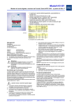
Operating instructions
Digital Output Module
for Zone 2
> 9475/33-08-.0
Contents
1
Contents
1
2
2.1
2.2
2.3
3
4
4.1
4.2
4.3
4.4
5
6
6.1
6.2
7
8
9
9.1
9.2
9.3
9.4
9.5
10
10.1
10.2
11
12
13
2
Contents ................................................................................................................2
General information ...............................................................................................2
Manufacturer .........................................................................................................2
Information regarding the operating instructions ...................................................2
Conformity with standards and regulations ...........................................................2
Symbols used ........................................................................................................3
General safety notes .............................................................................................3
Operating instructions storage ..............................................................................3
Safety notes ..........................................................................................................3
Alterations and modifications ................................................................................4
Special versions ....................................................................................................4
Intended use ..........................................................................................................4
Components ..........................................................................................................5
Overview ...............................................................................................................5
Pluggable terminal X1 ...........................................................................................5
Technical data .......................................................................................................6
Transport and storage ...........................................................................................8
Installation .............................................................................................................9
Dimensions / fastening dimensions .......................................................................9
Installation conditions ............................................................................................9
Mounting and operating position .........................................................................10
LED indications and troubleshooting ...................................................................11
Dismounting / replacement of the module ...........................................................12
Maintenance, overhaul and repair .......................................................................13
Maintenance ........................................................................................................13
Repair instructions ...............................................................................................13
Disposal ...............................................................................................................13
Accessories and spare parts ...............................................................................14
EC Declaration of Conformity ..............................................................................15
General information
2.1 Manufacturer
R. STAHL Schaltgeräte GmbH
Am Bahnhof 30
74638 Waldenburg
Germany
Phone:
Fax:
Internet:
+49 7942 943-0
+49 7942 943-4333
www.stahl-ex.com
2.2 Information regarding the operating instructions
ID-No.:
Publication code:
218140 / 9475612310
2013-05-08·BA00·III·en·00
2.3 Conformity with standards and regulations
Conformity with standards and regulations is specified in the corresponding certificates
and the EC Declaration of Conformity. These documents can be downloaded from our
homepage www.stahl-ex.com.
2
Digital Output Module for Zone 2
9475/33-08-.0
218140 / 9475612310
2013-05-08·BA00·III·en·00
Symbols used
3
Symbols used
Safety notes
Non-compliance can result in material damage, serious injuries or
death.
The safety notes contained in these operating instructions and affixed to the
device must be observed!
Warning symbol
Danger due to explosive atmosphere!
Warning symbol
Danger due to live components!
4
Note
This graphic marks important additional information, tips and
recommendations.
General safety notes
4.1 Operating instructions storage
Read these operating instructions carefully and store them near the installation place.
For correct operation, please observe all other documents enclosed in this delivery and
the operating instructions of the equipment to be connected.
4.2 Safety notes
WARNING
Use the devices only for their intended purpose!
We cannot be held liable for damage caused by incorrect or unauthorized
use or by non-compliance with these operating instructions.
Use the device only if it is undamaged and clean.
WARNING
Any unauthorized work on the device is prohibited!
Installation, maintenance, overhaul and repair may only be carried out by
authorized and appropriately trained personnel.
Observe the following information during installation and operation:
Any damage can invalidate the explosion protection
National and local safety regulations
National and local accident prevention regulations
National and local assembly and installation regulations
Generally recognized technical regulations
Safety notes in these operating instructions
Characteristic values and rated operating conditions on the rating plates and
data plates
Additional information plates on the devices
218140 / 9475612310
2013-05-08·BA00·III·en·00
Digital Output Module for Zone 2
9475/33-08-.0
3
Intended use
Additional safety notes:
The digital output module Type 9475/33-08 is approved for use in
gas hazardous areas of Zone 2 and in the safe area.
The digital output module Type 9475/33-08 is approved for use in
dust hazardous areas of Zone 21 and Zone 22.
For operation in gas or dust hazardous areas, the module must be installed in
an enclosure which fulfils the requirements of IEC/EN 60079-0.
The module must be mounted on the BusRail 9494 only.
A distance of 50 mm must be maintained between intrinsically safe and
non-intrinsically safe electric circuits.
Modules with intrinsically safe and non-intrinsically safe field circuits may be operated
simultaneously on one BusRail. In this case, a distance of 50 mm must be maintained
between the terminals of intrinsically safe and non-intrinsically safe electric circuits
(e.g. partition 220101 or empty space).
The safety-related maximum values of the connected field devices must match the
values of the modules according to data sheet, operating instructions and EC Type
Examination Certificate.
Interconnections of several active intrinsically safe circuits can result in different
safety-related maximum values. This can endanger the intrinsic safety so that an
appropriate proof must be provided.
Modules and plug connectors may be connected and disconnected during operation
in hazardous areas (hot-swap und hot-plug).
To avoid electrostatic charging, the modules in hazardous areas must be cleaned only
with a moist cloth.
4.3 Alterations and modifications
WARNING
Alterations and modifications to the device are not permitted.
We shall not accept any liability or warranty obligations for damage resulting
from alterations and modifications.
4.4 Special versions
In case of additional/different order options, special versions may differ from the
description given here.
5
Intended use
The digital output module is used for connecting of up to 8 intrinsically safe solenoid
valves, indication or signal elements to the IS1 remote I/O system. All channels are
individually monitored for wire breakage and short-circuit. The Ex i outputs are
short-circuit proof, galvanically connected to each and galvanically separated from the
system.
Compatible spare for IS1 I/O modules:
Series 9475/12-08-51, 9475/12-08-61, 9475/22-08-51 (without Plant STOP),
9475/22-08-61 (without Plant STOP)
4
Digital Output Module for Zone 2
9475/33-08-.0
218140 / 9475612310
2013-05-08·BA00·III·en·00
Components
6
Components
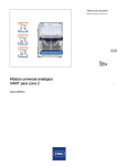
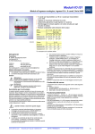
6.1 Overview
1
2
3
4
1
Operating flap with insert label (open) and connection diagram
2
Module data (serial number, hardware revision number, software revision number,
manufacturing date, e.g.: 123456DE9999 Rev.A 01-01 0508)
3
Notch lever for removing the module from the BusRail
4
LED for operation indication ("RUN", green), error ("ERR", red) and maintenance
("M/S", blue) (for further information, see "LED indications and troubleshooting")
5
Pluggable terminal X1
5
15323E00
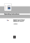
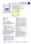
6.2 Pluggable terminal X1
For the module, a pluggable terminal X1 (screw-type terminal 162702 or spring clamp
terminal 162695) for connection of field devices is available as accessory (not included
in the scope of delivery of the module!).
The pluggable terminal X1 has 16 terminals for connection of the field cables.
X1
1
2
3
4
5
6
7
8
9 10 11 12 13 14 15 16
15324E00
Terminal assignment
X1
output signals
Channel
Terminals
0
1(+), 2(-)
1
3(+), 4(-)
2
5(+), 6(-)
3
7(+), 8(-)
4
9(+), 10(-)
5
11(+), 12(-)
6
13(+), 14(-)
7
15(+), 16(-)
218140 / 9475612310
2013-05-08·BA00·III·en·00
Digital Output Module for Zone 2
9475/33-08-.0
5
Technical data
7
Technical data
Explosion protection
Global (IECEx)
Gas and dust
Europe (ATEX)
Gas and dust
Certificates and approvals
Certificates
Further parameters
Installation
Safety data
Version
Max. voltage Uo
Output ia
Max. current Io
Max. power Po
Max. connectable
inductance Lo/capacity Co
IIC
IIB / IIIC
Output ib
Max. current Io
Max. power Po
Max. connectable
inductance Lo/capacity Co
IIC
IIB / IIIC
Max. internal capacity Ci
Max. internal inductance Li
6
IECEx DEK 12.0070X
Ex nA ia [ia Ga] IIC T4 Gc
[Ex ia Da] IIIC
DEKRA 12 ATEX0232X
E II 3 (1) Ex nA ia [ia Ga] IIC T4 Gc
E II (1) D [Ex ia Da] IIIC
IECEx, ATEX
in Zone 2, Zone 21, Zone 22 and in the safe area
9475/33-08-50
19.4 V
143 mA
692 mW
Lo [mH]
1.44
1.4
0.65
0.5
0.2
0.1
0.05
Co [nF]
--
103
113
113
153
183
227
Lo [mH]
7.5
5.0
2.0
0.5
0.2
0.1
0.02
Co [nF]
673
883
943
943
1083
1283
1493
Lo [mH]
6.3
2.0
0.65
0.5
0.2
0.1
0.05
Co [nF]
113
113
123
123
153
193
227
Lo [mH]
58
20
10
5.0
0.2
0.1
0.02
Co [nF]
363
723
953
963
1083
1283
1493
37.8 mA
506 mW
16.5 nF (in the above tables, Ci is subtracted from Co)
negligible
Digital Output Module for Zone 2
9475/33-08-.0
218140 / 9475612310
2013-05-08·BA00·III·en·00
Technical data
Output ib
Max. current Io
Max. power Po
Max. connectable
inductance Lo/capacity Co
IIC
IIB / IIIC
Max. internal capacity Ci
Max. internal inductance Li
Electrical data
Version
Ex i outputs
Number of channels
Open-circuit voltage
Output nominal current
Internal resistance
Rated operation
U
I
Output characteristic
107 mA
688 mW
Lo [mH]
1.57
1.1
1.0
0.9
0.5
0.2
0.1
Co [nF]
--
49
52
54
69
95
97
Lo [mH]
11
5.0
1.0
0.5
0.2
0.1
0.05
Co [nF]
335
335
395
485
635
785
785
Lo [mH]
7.0
5.0
2.0
1.0
0.5
0.2
0.05
Co [nF]
32
36
49
64
81
97
97
Lo [mH]
100
50
1.0
0.5
0.2
0.1
0.05
Co [nF]
245
365
425
505
655
785
785
26.3 mA
468 mW
5.2 nF (in the above tables, Ci is subtracted from Co)
negligible
9475/33-08-50
9475/33-08-60
8
17.5 V
30 mA
170 Ω
8
23.5 V
20 mA
315 Ω
12.6 V
30 mA
17.5 V
20 mA
25
25
U [V]
IIB / IIIC
9475/33-08-60
25.7 V
U [V]
Version
Max. voltage Uo
Output ia
Max. current Io
Max. power Po
Max. connectable
inductance Lo/capacity Co
IIC
20
20
15
15
10
10
5
0
5
0
5
10
15
20
25
30
35
0
0
5
10
15
20
25
30
I [mA]
15283E00
Galvanic separation
Test voltage
acc. to standard
Between auxiliary power/
system components
Between two I/O modules
Between I/O channels/
system components
Between I/O channels/
ground (PA)
Electromagnetic compatibility
Electrical connection
Power supply
Ex i field signals
Auxiliary power
Version
Behaviour during undervoltage
Max. current consumption
Max. power consumption
Max. power dissipation
218140 / 9475612310
2013-05-08·BA00·III·en·00
35
I [mA]
15284E00
EN 60079-11
) 1500 V AC
) 500 V AC
) 500 V AC
) 500 V AC
Tested to the following standards and regulations:
EN 61326-1 (2006) IEC 61000-4-1 … 6, NAMUR NE 21
BusRail Types 9494
Pluggable, blue terminals, 16-pole, 2.5 mm2, screw- or spring-type versions with
lock
Intrinsically safe Ex ia via BusRail
all outputs "OFF"
250 mA
6W
4.8 W
240 mA
5.8 W
4W
Digital Output Module for Zone 2
9475/33-08-.0
7
Transport and storage
Device-specific data
Settings
Module
Diagnosis messages
Signal
Power error control
Behaviour in case of error
Ambient conditions
Ambient temperature
Storage temperature
Maximum relative humidity
Semi-sinusoidal shock
(IEC EN 60068-2-27)
Sinusoidal vibration
(IEC EN 60068-2-6)
Mechanical data
Degree of protection (IEC 60529)
Module enclosure
Fire resistance (UL 94)
Pollutant class
Dimensions
Indication
LED indication
Module requires maintenance
Operating state
Group error
Function indication
Retrievable parameters
Error indication
Module status and alarms
Signal errors for each channel
Signal status bit
Wire breakage output
Short circuit output
Mounting / installation
Mounting orientation
Mounting type
8
ON / OFF
ON / ON without test current / OFF
ON / OFF / hold last value
-40 … +75 °C
-40 … +80 °C
95 % (without condensation)
15 g (3 shocks per axis and direction)
1 g in the frequency range 10 ... 500 Hz
2 g in the frequency range 45 ... 100 Hz
IP20
polyamide 6GF
V2
corresponds to G3
L = 128 mm, W = 96.5 mm, H = 67 mm
LED "M/S", blue
LED "RUN", green
LED "ERR", red
Manufacturer, Type, hardware revision, software revision, serial number
•
•
•
•
•
•
•
Internal bus error primer / redundant
No response from IOM
Configuration does not correspond to module
Hardware error
Excess temperature
Slot error
Module requires maintenance
"0" = output high-impedance / "1" = output is supplied
> 12 kΩ
(with deactivated test current can be detected only if the output is switched on)
< 30 Ω (response range 30 ... 60 Ω)
(can be detected only if the output is switched on)
horizontal or vertical (see chapter 9.3)
on 35 mm DIN rail LV 35/15 (DIN EN 60715)
Transport and storage
Transport and storage are only permitted in the original packaging.
The devices must be stored in a dry place and vibration-free.
8
Digital Output Module for Zone 2
9475/33-08-.0
218140 / 9475612310
2013-05-08·BA00·III·en·00
Installation
9
Installation
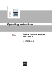
9.1 Dimensions / fastening dimensions
63 mm / 2.48 "
68 mm / 2.68 "
70 mm / 2.76 "
Dimensional drawings (all dimensions in mm / inches) - subject to modifications
98 mm / 3.86 "
96,5 mm / 3.8 "
128 mm / 5.04 "
01927E00
9.2 Installation conditions
WARNING
The national installation instructions (e.g. IEC/EN 60079-14) must be observed.
Ensure that there is a distance of at least 50 mm (safety distance) between
connecting units of intrinsically safe and non-intrinsically safe circuits!
WARNING
If the installation has strong electromagnetic sources of interference,
use of shielded field cables is recommended. In this case, the shield must be
connected to the equipotential bonding of the hazardous area! For this purpose,
the shields of the field wiring must be connected to the shield busses installed
in the enclosure as close to the entry point as possible!
The shield busses must be also connected to the mounting plate close to the
entry point of the field wiring using the shortest possible way!
218140 / 9475612310
2013-05-08·BA00·III·en·00
Digital Output Module for Zone 2
9475/33-08-.0
9
Installation
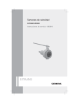
9.3 Mounting and operating position
Mounting the module on BusRail
NOTICE
The module and the pluggable terminal X1 can be safely connected or
disconnected during operation in the hazardous area (hot swap).
NOTICE
Module operation is permitted only in the following mounting positions:
Vertical mounting with pluggable terminals below, on the left or right.
BusRail
BusRail
05683E00
Position the module vertically on the provided slot of the BusRail
Snap module into place by slightly pressing it
Connecting field devices to the module
10
NOTICE
The mounting can be carried out with connected or disconnected terminals.
In the operating flap, there is a insert label which can be used for entering the
assignment of the field devices to the channels. Labelling of the insert label can
be performed, for example by means of the IS Wizard.
Connect field devices to terminal X1 according to terminal assignment (see on the front
or on insert label under the operating flap) (tightening torque for screw-type terminals
0.5 ... 0.6 Nm)
Place the field wiring shields (if present) as close to the entry point on the grounding
rail as possible
Plug the pluggable terminal X1 into the module and secure it against loosening using
safety screws (tightening torque 0.5 ... 0.6 Nm)
Mount partition if necessary (distance between intrinsically safe and non-intrinsically
safe electric circuits at least 50 mm)
Digital Output Module for Zone 2
9475/33-08-.0
218140 / 9475612310
2013-05-08·BA00·III·en·00
Installation
9.4 LED indications and troubleshooting
Meaning of the LEDs
15395E00
LED "RUN", green = operation indication
LED "ERR", red = module error indication
LED "M/S", blue = requires maintenance or outside specification
Indication overview
Module state
Error source
Possible solution
ON
Normal operation
--
--
FLASHES
In standby (switched on but
no data exchange with master
yet)
The module is in proper
condition but is not ready
for cyclic data exchange yet
(there is no parameter set
available yet). Outputs in a
state without power.
• Activate the cyclic data transfer with the
master
• Check master, bus connection and CPM
OFF
No function
No supply voltage at the
I/O module or I/O module is
defective.
•
•
•
•
OFF
No error
--
--
FLASHES
External error
Error in the field circuit:
wire breakage, short circuit
• Eliminate the cause in the indicated field
circuit, check electric lines and field device
Incorrectly configured module
Configuration is not correct or
a wrong module is connected
• Change configuration in the automation
system or connect the correct module
Outputs in safety position
Cyclic data transfer with the
automation system has been
interrupted
• Check the cyclic data transfer of CPM or
CPU (LCD or LED "RUN")
• Check bus connection
• Activate the cyclic data transfer with the
automation system
Module error
Module is defective
• Replace the module
OFF
Normal operation
--
--
FLASHES
External maintenance
required
Ambient temperature is
outside the specification
• Reduce ambient temperature by means
of, e.g. shading or cooling
Note: If the problem is not eliminated,
the module will be permanently
damaged
ON
Maintenance required
Slot error or module is
damaged by excess
temperature or end of the
service life reached
• Replace the module as soon as possible
within the next 12 months, otherwise there
is a risk of module failure
LED "RUN", green
Check system supply
Check CPM or CPU&PM
Check the BusRail
Engage the I/O module correctly on the
BusRail
• Replace the I/O module
LED "ERR", red
ON
LED "M/S", blue
218140 / 9475612310
2013-05-08·BA00·III·en·00
Digital Output Module for Zone 2
9475/33-08-.0
11
Installation
9.5 Dismounting / replacement of the module
WARNING
If a partition is mounted, first pull out terminal X1 from the module to be
replaced.
NOTICE
When replacing the module by a module identical in construction, the set
parameters are maintained. No further user adjustments are necessary.
When replacing the module by a module with a different function, the module
reports a configuration error (red LED "ERR" flashes). The module must be
either re-parameterised or it is necessary to use a module of the correct type.
NOTICE
If an IS1 module is replaced by an IS1+ module with the same functions,
the IS1+ module functions in the compatibility mode (= identical functionality).
If new IS1+ functions must be used, it may be necessary to update the software
of CPM 9440 or CPU 9441.
In case of PROFIBUS DP operation, a new GSD may be required. If required,
contact your responsible distributor for further information.
Loosen safety screws of the pluggable terminal X1
Pull out the terminals from the module
If necessary, remove the partition
Pull the blue notch lever of the module upwards to unlock the module
Remove the module vertically from the BusRail
Position the new module vertically onto the BusRail and snap into place by slightly
pressing it
If necessary, snap partition into place between modules
Plug the pluggable terminal X1 into the module and secure it against loosening using
screws (tightening torque 0.5 ... 0.6 Nm)
12
Digital Output Module for Zone 2
9475/33-08-.0
218140 / 9475612310
2013-05-08·BA00·III·en·00
Maintenance, overhaul and repair
10 Maintenance, overhaul and repair
10.1 Maintenance
The module does not require regular maintenance.
Observe the function according to the intended use
Follow the directives according to IEC/EN 60079-17
Adhere to permissible temperatures according to IEC/EN 60079-0
NOTICE
If the blue LED "M/S" lights up continuously, it is recommended to replace the
module in the foreseeable future. Otherwise there is a high probability that the
module will fail in 12 months (see "LED indications and troubleshooting").
10.2 Repair instructions
NOTICE
Repair must be performed by the manufacturer only!
When repair is required, send the module to your responsible sales
organization (for the address, see chapter 2.1).
11 Disposal
Observe the national waste disposal regulations.
218140 / 9475612310
2013-05-08·BA00·III·en·00
Digital Output Module for Zone 2
9475/33-08-.0
13
Accessories and spare parts
12 Accessories and spare parts
WARNING
Explosion hazard due to wrong or insufficient spare parts or
wrong accessories!
For components with relevant Ex protection, use only suitable, certified spare
parts or corresponding accessories of R. STAHL Schaltgeräte GmbH or other
manufacturers. Otherwise, explosion protection cannot be guaranteed any
longer.
R. STAHL Schaltgeräte GmbH cannot be held liable for damage caused by
ignoring this danger.
Designation
Figure
Description
Art. no.
Weight
kg
Plug-in terminal
2.5 mm with lock, 16-pole, screw connector, blue,
for connecting the field signals to I/O modules,
for intrinsically safe field circuits
Labelling: 1 ... 16
162702
0.028
2.5 mm2 with lock, 16-pole, spring clamp connection,
blue, for connecting the field signals to I/O modules,
for intrinsically safe field circuits, incl. test jacks
Labelling: 1 ... 16
162695
0.028
The mA isolating repeaters are used for the connection
of 4-wire transmitters to active 2-wire inputs and for the
galvanic separation.
Input: sink, Ex e
Output: sink, Ex i
160166
0.107
The mA isolating repeaters are used for the connection
of 4-wire transmitters to active 2-wire inputs and for the
galvanic separation.
Input: sink, Ex i
Output: sink, Ex i
160165
0.075
"FB Addr ... Mod No ..." for pluggable terminal,
sheet with 26 strips
162788
0.001
For label plate on I/O modules; 6 labels on each sheet;
print-out using IS Wizard; packaging unit = 20 sheets
162832
0.001
For mounting between intrinsically safe and
non-intrinsically safe connections of the I/O modules,
in order to adhere to the required 50 mm distance
220101
0.000
"Clean modules only with a damp cloth."
162796
0.001
2
02079E00
02077E00
mA - Isolating
Repeater
10389E00
04653E00
Labelling strips
05869E00
DIN A4 sheet
09900E00
Partition
15196E00
Warning sign
05872E00
14
Digital Output Module for Zone 2
9475/33-08-.0
218140 / 9475612310
2013-05-08·BA00·III·en·00
EC Declaration of Conformity
13 EC Declaration of Conformity
218140 / 9475612310
2013-05-08·BA00·III·en·00
Digital Output Module for Zone 2
9475/33-08-.0
15
The IS1 resp. IS1+ Remote I/O is a DIN rail mounted system designed
to record and output process control signals between hazardous
location transducers and sensors and a nonhazardous location
automation system. It consists of electrical apparatus in the
nonhazardous, Class I, Division 2 or Class I, Zone 2 hazardous
locations linked by either nonincendive field bus or a field bus installed
per the National Electrical Code, ANSI/NFPA 70 Article 500.
Control Room
DCS
PLC
RS 485
Fieldbus Isolating
Repeater type
9185/12 Repeater /
Interface conector
Nonhazardous
Location
The nonincendive field bus circuit is achieved with the use of the
Fieldbus Isolating repeater type 9185. This device resides in the
nonhazardous location and provides a nonincendive field bus circuit
for connection to the IS1 resp. IS1+ Remote I/O System. See example
to the left.
nonicendive fieldbus
Division 2
Zone 2
The apparatus located in the Division 2 or Zone 2 hazardous location
are referred to as Remote I/O, and consist of the following major
subsystems.
Division 1
Zone 1
Division 1
Zone 0
1.
CPU & Power Module or CPU Module, Power Module & Socket
The CPU & Power Module or the Power Module serves as a
power supply unit for its CPU unit or the CPU Module, as well as
for the supply to the I/O Modules and the field circuits. The power
supply to the I/O modules is implemented via the BusRail. For the
configuration with a redundant CPU and Power Module the power
supply to the I/O modules is decoupled with diodes. The power
supply unit has an under voltage monitoring circuit. The CPU
fulfils the function of a gateway between the internal bus of an IS1
field station and the fieldbus which connects the field station with
the automation system. The gateway is constructed as a dual
processor system. The I/O processor controls the data exchange
with the I/O modules and, when plugged-in, with the redundant
CPU & Power Module. The communication processor controls the
data exchange on the fieldbus and on the Service Bus.
2.
BusRail
The BusRail provides a Power bus, an internal data bus and the
address lines for the interconnection of the CPU & Power Supply
to Remote I/O modules The Power bus distributes power supplied
by the CPU & Power Module to the I/O Modules plugged to the
BusRail. The communication with the I/O Modules is implemented
via the address and date bus lines. The interface of the CPU &
Power Module with the internal data bus on the BusRail is
designed with redundancy.
3.
Components of Remote I/O System
All I/O Modules are manufactured in a unique DIN rail mount
package which then mounts onto the Remote I/O system BusRail.
All I/O Modules provide galvanic isolation between the field
circuits and the BusRail’s circuits.
4.
Refer to pages 3 through 26 for information specific to each
module.
Example: System Topology interfacing
Automation control systems with DIV 2 / Zone 2
Installation of IS1 resp. IS1+ Remote I/O System
I.S. 1 Wizard
This is the PC software configuration
package used for commissioning, troubleshooting and MODBUS / HART configuration
RS 232
Fieldbus Isolating
Repeater Type
9185/12
RS 232 to RS 485
conversion
Nonhazardous
Location
Nonincendive fieldbus
...
1
2
18
Division 2
Zone 2
Service Bus with Isolating Repeater interface
GENERAL NOTES:
1.
2.
Mounting direction upwards:
BusRail
BusRail
3.
BusRail
4.
5.
Installation should be in accordance with Article 504/505 of the
National Electrical Code, ANSI/NFPA 70 and ANSI/ISA
RP12.06.01 resp. with the Canadian Electrical Code, Part I.
Use a general purpose enclosure meeting the requirements of
ANSI/ISA S82 for use in nonhazardous or Class I, Division 2
hazardous (Classified) Locations.
Use an FMRC Approved or NRTL listed Dust-ignition proof
enclosure appropriate for environment protection in Class II,
Division 1, Groups E, F and G; and Class III, hazardous
(Classified) Locations.
All I/O Modules may be detached from the BusRail or plugged
onto it during operation in hazardous areas.
The Modules may be operated in one of the three mounting
positions only.
2013
08.02.
02
01
26.02.2014 Bagusch
17.02.2014 Bagusch
Reistle
Kaiser
none
IS1 resp. IS1+ Remote I/O System
for CL I, DIV 2 / Zone 2
Overview
1 of 30
9400 6 031 002 1
FM
Nonhazardous
Class I, II, III, Division 2, Group A-G
or Class I, Zone 2, Group IIC/IIB
Hazardous (Classified) Locations
Input for “Plant-stop”
only at type 9475/3*-0*-*2
The Type 9475 Digital Output Module is designed to receive a digital
signal from the IS1 CPU & Power Module and output a corresponding
discrete signal to solenoid valves, LED initiators and audible alarms.
The module is nonincendive for installation in a Class I, II, III, Division
2, Group A-G or Class I, Zone 2, Group IIC/IIB hazardous location
according to NEC Article 504/505 and provides intrinsically safe
connections for Class I, Division 1, Groups A-G or Class I, Zone 0,
Group IIC/IIB hazardous locations.
Entity parameters for wiring configuration to the left are as follows:
CL I,II,III, DIV 1, Group A-G or CL I, Zone 0, Group IIC
9475/3*-04-1*
9475/3*-04-2*
9475/3*-04-3*
9475/3*-08-4*
9475/3*-08-5*
9475/3*-08-6*
VOC
[V]
19.7
25.7
26.0
11.5
19.4
25.7
ISC
[mA]
142
110
90
74.8
143
107
PO
[mW]
698
708
585
216
692
688
Ci
[nF]
11
7.2
5.2
5.2
16.5
5.2
Li
[mH]
0
0
0
0
0
0
CL I,II,III, DIV 1, Group A-G or CL I, Zone 1, Group IIC
9475/3*-04-1*
9475/3*-04-2*
9475/3*-04-3*
9475/3*-08-4*
9475/3*-08-5*
9475/3*-08-6*
9475/3*-04-7*
VOC
[V]
19.7
25.7
26.0
11.5
19.4
25.7
15.4
ISC
[mA]
53.8
49.5
50.4
39.2
37.8
26.3
115.4
PO
[mW]
617
648
508
194
506
468
1475
Ci
[nF]
11
7.2
5.2
5.2
16.5
5.2
33
Li
[mH]
0
0
0
0
0
0
0
“Plant-stop I” at 9475/33-0*-*2 only, Connection X3
CL I,II,III, DIV 1, Group A-G or CL I, Zone 0, Group IIC
Terminal 1(+),24(-)
(3-4 open)
9475/3*-0*-*2
FM approved intrinsically safe
solenoid valves, indicating lamps
Wiring legend
Connection allocation – Digital Output Module Type 9475/3*-0*-**
DOM (4 channels)
9475/3*-04-**
Connection X1
Channel no.
0
1
2
3
4
5
6
7
Channel no.
0
1
2
3
-
Terminal no.
1(+), 2(-)
3(+), 4(-)
5(+), 6(-)
7(+), 8(-)
9(+), 10(-)
11(+), 12(-)
13(+), 14(-)
15(+), 16(-)
WARNING:
Substitution of components may impair Intrinsic
Safety.
AVERTISSEMENT: Substitution de composants peut
compromettre la sécurité intrinsèque.
ISC
[mA]
0.44
PO
[mW]
0.50
Vi
[V]
30
Ri
[Ω]
4940
Ci
[nF]
0
Reistle
Kaiser
Li
[mH]
0
Li
[mH]
0
Notes:
1. Intrinsically safe apparatus shall be LEDs or an FM approved
System or Entity device connected in accordance with the
manufacturer´s installation instructions.
2. For Entity concept use the appropriate parameters from above to
ensure the following:
VOC or Vt Vmax
Ca Ci + Cleads
ISC or It Imax
La Li + Lleads
3. Capacitance and Inductance values for circuit with concentrated
inductors and capacitors for each type 9475/3* are on sheet 21
and 22.
4. Suitable separation must be maintained between wiring of each
I.S. input channel.
5. Suitable separation must be maintained between non I.S. / AEx
nA wiring of the input circuits and I.S. wiring of other I/O modules
and of the IS1 resp. IS1+ system. Use partition (SAP No. 220101)
for separation from I/O modules with I.S. circuits. Do not carry out
work at the terminals without the partition plate in place.
6. General Notes (see Page 1)
2013
08.02.
Ci
[µF]
5.2
“Plant-stop II” at 9475/3*-0*-*2 only, Connection X3
CL I,II,III, DIV 1, Group A-G or CL I, Zone 0, Group IIC
Terminal 3(+), 4(-)
(1-2 open)
9475/3*-0*-*2
DOM (8 channels)
9475/3*-08-**
VOC
[V]
5.1
Digital Output Module
Type 9475/3b-**-** (b = 2 or 3)
none
20 of 30
02
01
26.02.2014 Bagusch
17.02.2014 Bagusch
9400 6 031 002 1
FM
The internal capacitance per channel is already taken into account in the Lo and Co values shown in the tables below. The internal inductance is
negligibly small.
Type 9475/3*-04-1* Capacitance and Inductance values
CL I, DIV 1, Group A,B
CL I, Zone 0, Group IIC
Lo [mH]
1.3
1.1
0.5
0.2
0.1
0.05
Co [nF]
99
109
119
149
189
220
CL I, DIV 1, Group C-G
CL I, Zone 0, Group IIB/IIIC
Lo [mH]
7.5
5.0
2.0
0.5
0.2
0.1
0.05
Co [nF]
669
879
889
889
989
1189
1439
Type 9475/3*-04-2* Capacitance and Inductance values
CL I, DIV 1, Group A,B
CL I, Zone 0, Group IIC
Lo [mH]
1.45
0.75
0.5
0.37
0.2
0.1
0.05
Co [nF]
56
67
76
93
95
95
CL I, DIV 1, Group C-G
CL I, Zone 0, Group IIB/IIIC
Lo [mH]
10.0
5.0
2.0
1.0
0.5
0.2
0.1
Co [nF]
323
323
333
393
473
633
783
Type 9475/3*-04-3* Capacitance and Inductance values
CL I, DIV 1, Group A,B
CL I, Zone 0, Group IIC
Lo [mH]
2.44
2.2
1.0
0.5
0.38
0.2
0.05
Co [nF]
39
55
71
79
94
94
CL I, DIV 1, Group C-G
CL I, Zone 0, Group IIB/IIIC
Lo [mH]
16.0
10.0
2.0
1.0
0.5
0.2
0.1
Co [nF]
335
335
345
395
475
625
765
Type 9475/3*-08-4* Capacitance and Inductance values
CL I, DIV 1, Group A,B
CL I, Zone 0, Group IIC
Lo [mH]
7.9
5.0
2.0
1.0
0.5
0.2
0.05
Co [nF]
285
395
585
735
905
1195
1635
CL I, DIV 1, Group C-G
CL I, Zone 0, Group IIB/IIIC
Lo [mH]
34.0
20.0
10.0
5.0
1.0
0.2
0.02
Co [nF]
1195
1695
2195
2695
4295
6995
11195
Type 9475/3*-08-5* Capacitance and Inductance values
CL I, DIV 1, Group A,B
CL I, Zone 0, Group IIC
Lo [mH]
1.44
1.4
0.65
0.5
0.2
0.1
0.05
Co [nF]
103
113
113
153
183
227
CL I, DIV 1, Group C-G
CL I, Zone 0, Group IIB/IIIC
Lo [mH]
7.5
5.0
2.0
0.5
0.2
0.1
0.02
Co [nF]
673
883
943
943
1083
1183
1493
Type 9475/3*-08-6* Capacitance and Inductance values
CL I, DIV 1, Group A,B
CL I, Zone 0, Group IIC
Lo [mH]
1.57
1.1
1.0
0.9
0.5
0.2
0.1
Co [nF]
49
52
54
69
95
97
CL I, DIV 1, Group C-G
CL I, Zone 0, Group IIB/IIIC
Lo [mH]
11.0
5.0
1.0
0.5
0.2
0.1
0.05
Co [nF]
335
335
395
485
635
785
785
Type 9475/3*-0*-*2,
“Plant-stop I” Capacitance and Inductance values
CL I, DIV 1, Group A,B
CL I, Zone 0, Group IIC
Lo [mH]
100
10
2.0
1.0
0.2
0.01
Co [nF]
2195
2595
3295
3695
5495
15995
CL I, DIV 1, Group C-G
CL I, Zone 0, Group IIB/IIIC
Lo [mH]
100
10
2.0
1.0
0.2
0.01
Co [nF]
9995
12995
16995
19995
31995
159995
2013
08.02.
02
01
26.02.2014 Bagusch
17.02.2014 Bagusch
Reistle
Kaiser
none
Digital Output Module
Type 9475/3b-**-** (b = 2 or 3)
(continued from sheet 20)
21 of 30
9400 6 031 002 1
FM
The internal capacitance per channel is already taken into account in the Lo and Co values shown in the tables below. The internal inductance is
negligibly small.
Type 9475/3*-04-1* Capacitance and Inductance values
CL I, DIV 1, Group A,B
CL I, Zone 1, Group IIC
Lo [mH]
3.1
2.0
0.6
0.5
0.2
0.1
0.05
CL I, DIV 1, Group C-G
CL I, Zone 1, Group IIB/IIIC
Co [nF]
109
109
119
119
149
189
220
Lo [mH]
27.0
20.0
10.0
5.0
0.2
0.1
0.05
Co [nF]
499
609
869
899
1089
1189
1439
Type 9475/3*-04-2* Capacitance and Inductance values
CL I, DIV 1, Group A,B
CL I, Zone 1, Group IIC
Lo [mH]
1.5
1.0
0.86
0.5
0.37
0.2
0.1
Co [nF]
43
51
55
69
76
93
95
CL I, DIV 1, Group C-G
CL I, Zone 1, Group IIB/IIIC
Lo [mH]
24.0
20.0
2.0
1.0
0.5
0.2
0.1
Co [nF]
333
333
343
393
483
633
783
Type 9475/3*-04-3* Capacitance and Inductance values
CL I, DIV 1, Group A,B
CL I, Zone 1, Group IIC
Lo [mH]
3.4
2.4
2.0
1.0
0.5
0.39
0.2
Co [nF]
35
41
44
57
73
80
94
CL I, DIV 1, Group C-G
CL I, Zone 1, Group IIB/IIIC
Lo [mH]
32.0
20.0
1.0
0.5
0.2
0.1
0.05
Co [nF]
345
345
405
485
635
765
765
Type 9475/3*-04-7* Capacitance and Inductance values
CL I, DIV 1, Group A,B
CL I, Zone 1, Group IIC
Lo [mH]
0.11
0.1
0.05
0.02
0.01
Co [nF]
257
267
337
477
488
CL I, DIV 1, Group C-G
CL I, Zone 1, Group IIB/IIIC
Lo [mH]
2.9
2.0
1.0
0.5
0.05
0.02
Co [nF]
1467
1767
2367
2667
2767
3157
Type 9475/3*-08-4* Capacitance and Inductance values
CL I, DIV 1, Group A,B
CL I, Zone 1, Group IIC
Lo [mH]
22.0
10.0
5.0
2.0
1.0
0.5
0.05
Co [nF]
155
345
475
635
775
935
1635
CL I, DIV 1, Group C-G
CL I, Zone 1, Group IIB/IIIC
Lo [mH]
100.0
50.0
20.0
5.0
1.0
0.2
0.02
Type 9475/3*-08-5* Capacitance and Inductance values
CL I, DIV 1, Group A,B
CL I, Zone 1, Group IIC
Lo [mH]
6.3
2.0
0.65
0.5
0.2
0.1
0.05
Co [nF]
113
113
123
123
153
193
227
CL I, DIV 1, Group C-G
CL I, Zone 1, Group IIB/IIIC
Lo [mH]
58.0
20.0
10.0
5.0
0.2
0.1
0.02
02
01
26.02.2014 Bagusch
17.02.2014 Bagusch
Reistle
Kaiser
Co [nF]
363
723
953
963
1083
1283
1493
Type 9475/3*-08-6* Capacitance and Inductance values
CL I, DIV 1, Group A,B
CL I, Zone 1, Group IIC
Lo [mH]
7.0
5.0
2.0
1.0
0.5
0.2
0.05
Co [nF]
32
36
49
64
81
97
97
CL I, DIV 1, Group C-G
CL I, Zone 1, Group IIB/IIIC
Lo [mH]
100.0
50.0
1.0
0.5
0.2
0.1
0.05
Co [nF]
245
365
425
505
655
785
785
Type 9475/3*-04-7* remaining capacitance and inductance values
taking into account the cable connected
CL I, DIV 1, Group A,B
CL I, Zone 1, Group IIC
CL I, DIV 1, Group C-G
CL I, Zone 1, Group IIB/IIIC
When using cables with a
line length < 700m,
with Lc ≤ 1 µH/m, Cc ≤ 200
pF/m and Rc ≥ 10.76 mΩ/m
When using cables with a
line length < 2000m,
with Lc ≤ 1 µH/m, Cc ≤ 200
pF/m and Rc ≥ 10.76 mΩ/m
Lo [mH]
0.05
Co [nF]
217
Lo [mH]
2.0
1.0
0.5
0.02
2013
08.02.
Co [nF]
565
1295
1895
2895
4395
6995
11195
Co [nF]
1667
2367
2667
3967
none
Digital Output Module
Type 9475/3b-**-** (b = 2 or 3)
(continued from sheet 21)
22 of 30
9400 6 031 002 1
FM