1
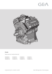
Betriebsanleitung FK 40
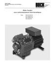
Operating instructions FK 40
FK 4 0 型 车 用Instructions
压 缩 机 使 用 说 明
de service FK 40
Istruzioni per l’uso FK 40
Isþletme kilavuzu FK 40
使 用 说 明 FK 40
FK 40 型 车 用 压 缩 机
型 号:
09716-03.03-DGbFITrRc
FK 40/390 N
FK 40/390 K
FK 40/390 TK
FK 40/470 N
FK 40/470 K
FK 40/470 TK
FK 40/560 N
FK 40/560 K
FK 40/560 TK
FK 40/655 N
FK 40/655 K
FK 40/655 TK
D
GB
F
I
TR
RC
FK 40
Operating instructions
D
-1-
GB
09716-07.07-DGbFITrRc
Types:
FK 40/390 N
FK 40/390 K
FK 40/390 TK
FK 40/470 N
FK 40/470 K
FK 40/470 TK
FK 40/560 N
FK 40/560 K
FK 40/560 TK
F
FK 40/655 N
FK 40/655 K
FK 40/655 TK
I
TR
RC
-1-
Foreword
Dear Customer,
Bock compressors are top-quality, reliable, service-friendly quality products. Please comply with the
following operating and maintenance instructions so that you can benefit from all advantages to the
full and use your refrigerating system throughout its entire service life. If you have any questions
about installation, operation and accessories, please contact our technical service or your refrigerating
system wholesale dealer or our representative. The Bock service team is available by phone under
+49 7022 9454-0, by e-mail under [email protected] or on the internet under www.bock.de. In addition, for German speaking countries we have set up a toll-free hotline under 00 800 / 800 00 88 from
Monday to Saturday between 8 a.m. and 9 p.m. Any suggestions you may have regarding the ongoing development of our compressor, equipment and parts programme are welcome at any time.
Please read the information summarised for you in
this manual before starting work.
It contains important instructions for safety, installation,
initial commissioning and handling. In addition you will
find information on maintenance, spare parts and accessories.
Some instructions are identified by special symbols with
the following meaning:
WARNING This symbol is used to indicate
that inaccurate compliance or total failure
to comply with the instructions could cause
injury to persons or damage to the compressor or refrigerating machine
D
GB
F
I
TR
Bock Kältemaschinen GmbH
RC
Postfach 11 61
D-72632 Frickenhausen
The high quality standard of Bock compressors is guaranteed also by on-going further development of machine,
features and accessories. This could possibly result in
nonconformities between this present manual and your
compressor. Please understand that it is not possible for
any claims to be derived from the details, illustrations and
descriptions.
Your team at
Bock Kältemaschinen GmbH
Benzstr. 7
D-72636 Frickenhausen
-2-
Fon: +49 7022 9454-0
Fax: +49 7022 9454-137
[email protected]
www.bock.de
- Subject to modifications -
09716-07.07-DGbFITrRc
This symbol indicates important additional
instructions which you should observe
during your work.
09716-07.07-DGbFITrRc
Contents
Page
Safety instructions
Product description
Use as intended
Short description
Nameplate
Type code
Main and functional components
Limits of application
N- and K-version
Limits of application R134a
Limits of application R407C
TK-version
Limits of application R404A/R507
Limits of application R22
Installation instructions
Mounting the compressor
Inclined position
Belt drive
Main bearing load
Installation of electromagnetic clutch
Pipe connections / pipes
Shut-off valves
Putting into operation
Leak test, evacuation
Refrigerant filling
Oil level check
Tightness of the shaft seal
Replacement of the axial face seal
Liquid operation
Maintenance
Safety instructions
Service intervals
Recommended spare parts
Integrated overcurrent safety valve
Excerpt from the lubricant table
Screwed unions
Decommissioning
Accessories
Capacity regulation
Heat protection thermostat
Specifications, Connections
Dimensions
Manufacturer declaration
4
5
5
5
5
5
6
7
7
7
8
8
8
9
10
10
10
11
11
11
12
12
13
13
13
13
14
14
14
15
15
15
15
15
16
16
16
17
17
17
18
19
20
D
GB
F
I
TR
RC
-3-
Safety
Safety
The Bock refrigerating compressors named in the title are intended for installation in machines (within
the EU according to EU directive 98/37/EC Machinery Directive, 97/23/EC Pressure Equipment
Directive and 73/23/EC Low Voltage Directive). Initial commissioning is only allowed when the
compressor has been installed according to these instructions and the whole machine in which it is
integrated has been tested and accepted according to the statutory regulations.
Bock refrigerating compressors have been designed to state-of-the-art engineering. Safety for the user
is given particular priority during the design stage. However, it is always possible for the refrigerating
machine and operation thereof to pose unavoidable residual risks. This is why these instructions
must be observed carefully by every person working at the compressor.
Work on the compressor may only be carried out by persons whose technical training, skills and
experience together with their knowledge of pertinent regulations and documentation means that
they are capable of assessing the work to be carried out and detecting any possible dangers
(trained staff as per DIN 31000).
SAFETY INSTRUCTIONS
Only qualified staff are allowed to handle refrigerating compressors.
National safety regulations, accident prevention regulations, technical rules and other
specifications (incl. EN 378 etc.) must be observed
The compressor may only be operated in refrigerating systems, and only with coolants
approved for this compressor by Bock.
The maximum tolerable operating overpressure may not be exceeded (not even
for test purposes).
Pressure switches are required to safeguard the machine from excess pressures.
New compressors are provided with an inert gas filling in the factory (approx. 3 bar
nitrogen) The pressure in the compressor must be relieved before connecting up
the refrigerating system.
Before starting the compressor, check for any signs of transport damage.
Before starting up, check that all components mounted by the user have been properly
fitted and are connected pressure-tight with the compressor (e.g. pipelines, bungs,
union nuts, replaced parts, etc.)
Before starting up, evacuate the refrigerating machine carefully with the compressor
and then fill with coolant.
Before starting the compressor, open the discharge shut-off valve and suction
shut-off valve.
Do not start the compressor in a vacuum. Only operate the compressor when the
whole system has been filled.
Surface temperatures of more than 100°C are possible on the pressure side respectively
below 0°C on the suction side, depending on operating conditions.
D
GB
F
I
TR
RC
-4-
09716-07.07-DGbFITrRc
Caution! Refrigerating compressors are pressurised machines and therefore require
particularly careful and meticulous handling.
Product description
Use as intended
This operating manual describes FK40 in the standard version produced by BOCK. The vehicle
compressors in series FK40 are designed for mobile use (other applications on request).
Short description
Three design variations are available for different areas of application:
> for air conditioning
the K Design
> for air conditioning or normal cooling the N Design
> for deep freezing
the TK Design
The differences are mostly associated with the valve plate version which is adapted to each
application range where operational safety and efficiency are concerned.
Additional features:
Compact four-cylinder compressor in V-design
Low-wearing long-lifed mechanism
Four sizes
Light-weight aluminium design
Crankshaft mounted on either side with roller bearings
Lubrication oil pump independent of the direction of rotation, with oil relief valve
Variable arrangement of the shut-off valves
Ideal valve plate configuration for every working range
Integrated pulsation damper for extremely quiet running
Nameplate (Exemple)
AP12345A017
4
1
2
3
19/28bar
5
1. Type of compressor
4. Serial number
2. Displacement at 1450 rpm
5. Oil type filled in compressor by the manufacturer
3. LP: max. tol. standstill pressure intake side
note limits of
HP: max. tol operating pressure high pressure side application diagrams!
Type key (Example)
Explanation of the type designation
D
09716-07.07-DGbFITrRc
}
GB
F
I
FK X 40 / 655 N
TR
RC
Application
Capacity size
Size
Ester oil filling (fluorocarbons, e.g. R134a, R407C)
Series
-5-
Product description
Main and functional components
1
2
3
4
5
18
11
6
7
8
12
9
13
14
10
15
16
D
GB
I
TR
RC
-6-
1.
2.
3.
4.
5.
6.
7.
8.
9.
Discharge shut-off valve
Valve plate
Cylinder cover
Compressor housing
Adapter for magnetic clutch
Integrated leakage oil collector
Leak oil drain hose
Axial face seal
Shaft end
10.
11.
12.
13.
14.
15.
16.
17.
18.
Base plate
Connection for heat protection thermostat
Oil filler plug
Oil sight glasses (2x)
Oil drain plug
Suction shut-off valve
Oil pump
Oil drain plug / oil filter
Nameplate
09716-07.07-DGbFITrRc
17
F
Limits of application
Areas of application
Explanations
It is possible to operate the compressor within the shown diagrams. Please note the significance of
the areas shaded in grey. The application limits must be observed. The max. discharge temperature of 140 °C and the max. ambient temperature of 100°C may not be exceeded.
Thresholds should not be selected as design or continuous operating points.
● Avoid continuous operation in the limit range. If nevertheless the compressor is used for operation
in the limit range, we recommend use of a thermal protective thermostat (accessory).
● Switching frequency: The compressor should not be started more frequently then 12 times per
hour, and should not run for less than 2 minutes at a time.
● The limits of application can be altered when using capacity regulators.
N- and K-version
Available models:
● FK 40/390 N
● FK 40/390 K
● FK 40/470 N
● FK 40/470 K
● FK 40/560 N
● FK 40/560 K
● FK 40/655 N
● FK 40/655 K
Limits of application R134a (Version N and K)
Speed range:
N-version: 500 - 3000 rpm (peak rotational speed 3500 rpm)
K-version: 500 - 3500 rpm
Max. tol. operating pressure (high pressure side, HD): 28 bar
Unrestricted area
of application
Reduced suction
gas temperature
09716-07.07-DGbFITrRc
R134a
D
evaporation temperature [°C]
GB
condensing temperature [°C]
F
suction gas temperature [°C]
I
suction gas overheating [K]
TR
RC
Designs for other areas upon request.
-7-
Limits of application
Limits of application R407C (Version N and K)
Speed range:
N-version: 500 - 2600 rpm (peak rotational speed 3500 rpm)
K-version: 500 - 3500 rpm
Max. tol. operating pressure (HP): 28 bar
Unrestricted area
of application
Reduced suction
gas temperature
evaporation temperature [°C]
R407C
condensing temperature [°C]
suction gas temperature [°C]
suction gas overheating [K]
TK-Version
Available models:
● FK 40/390 TK
● FK 40/470 TK
● FK 40/560 TK
● FK 40/655 TK
Limits of application R404A/R507 (TK version)
Speed range:
TK-version: 500 - 2600 rpm
Max. tol. operating pressure (HP): 28 bar
D
Unrestricted area
of application
GB
F
I
evaporation temperature [°C]
TR
R404A/R507
RC
condensing temperature [°C]
suction gas temperature [°C]
suction gas overheating [K]
-8-
Designs for other areas upon request.
09716-07.07-DGbFITrRc
Reduced suction
gas temperature
Limits of application
Limits of application R22 (TK version)
Speed range:
TK-version: 500 - 2600 rpm
Max. tol. operating pressure (HP): 28 bar
Unrestricted area
of application
Reduced suction
gas temperature
evaporation temperature [°C]
R22
condensing temperature [°C]
suction gas temperature [°C]
suction gas overheating [K]
D
GB
F
09716-07.07-DGbFITrRc
I
TR
RC
Designs for other areas upon request.
-9-
Installation instructions
Mounting the compressor
Transport and suspension possibilities at the transport eyelet or directly
at the pressure shut-off valve.
Bock must be consulted before any other components (e.g. pipe
brackets, additional appliances etc.) may be mounted to the
compressor
Proper erection of the compressor and installation of the belt
drive play a major role in the running comfort, operating safety
and service life of the compressor.
Warning! Compressor is under pressure!
● Avoid injuries to skin and eyes. Wear goggles!
● Leave protective gas filling in the compressor up to evacuation.
● Absolutely avoid entry of air!
● Do not open shutoff valves up to evacuation.
Pipe connections
GB
F
I
TR
RC
- 10 -
Caution when soldering!
Do not overheat the valve.
Cool the valve body during and after soldering.
Remove screw connections from the valve for soldering.
09716-07.07-DGbFITrRc
D
The pressure and suction shutoff valves have graduated
Inclined position
inside diameters, so that pipes in the customary millimeter
Please note the max. tolerable inclined position:
and inch dimensions can be used. The pipe will be
immersed more or less deeply according to dimension.
The connection diameters of the shutoff valves are designed
for the maximum compressor output. The actually required
pipe cross-section must be adapted to the power. The
Fig.: schematic
same applies for non-return valves.
Belt drive
Incorrectly executed belt drives, particularly belt hammers or excessive belt tension, can cause
damage to the compressor!
When using capacity regulators (accessories), the changing load can result in increased running noise and vibration of the belt drive.
Please ensure that the belt drive is designed accordingly (use of tensioning pulleys,
selection of belt profile and belt length, etc.)
Main bearing load
The following should be observed to avoid overloading of the
compressor’s main bearing, e.g. by the belt drive:
The force applied to the point of acting forces (see fig.) may not
exceed Fmax = 2750 N.
If this point of acting force is moved forward (see fig., small dots)
then the force Fmax is diminished according to the following formula:
Fmax
F = 245 kNmm / (90mm + L1 [mm])
Incorrectly executed belt drives, particularly belt beats due
to jumping belts or excessive tensioning forces, can result
in compressor damage.
L1
(m
m)
Fmax = 2750 N
(Mbmax = 245 kNmm)
Installation of electromagnetic clutch
The subsequent description applies to an electromagnetic clutch type LA 16 made by Linnig.
For centering and mounting the magnetic coil of clutch, the front bearing flange has a snug fit
of ø148 h8 (see left fig.).
To install the magnetic coil, unscrew the 4 socket head screws M8 on the bearing flange (see
circles and arrows, fig.).
Mount the magnetic coil on the seat (snug fit), and secure with the four socket head screws M8
(right fig.). Screw tightening torque = 34 Nm.
Continue with the installation of the electromagnetic coupling according to the instructions of
the clutch manufacturer.
D
GB
F
09716-07.07-DGbFITrRc
I
TR
RC
- 11 -
Installation instructions
Pipe connections / pipes
The pipe connections are designed in such a way that pipes of all normal metric and inch dimensions
can be used. The solder connections of the shut-off should be removed during soldering.
The pipes and unit components should always be clean and dry on the inside, and free of
cinders, metal chips, rust and phosphate coats. Furthermore the parts, including the hoses, must
be delivered sealed air-tight.
Shut-off valves
Opening the shut-off valve
a) Open spindle 1: to the left (anti-clockwise) as far as
it will go. → Shut-off valve fully opened / service
connection 2 closed (setting A),fig.
Opening the service connection (2)
b) Turn spindle 1: 1/2 - 1 turn to the right (clockwise).
→ Service connection 2 opened / shut off valve open
(setting B), fig. Connection 3 is for safety purposes
and not lockable.
Position A
Position B
Note: Before opening or closing the shut-off valve, loosen the valve spindle seal (fig.
left) 1/4 of a turn. Tighten the valve spindle seal again carefully after activating the
shut-off valve (fig. right).
D
GB
I
TR
RC
- 12 -
09716-07.07-DGbFITrRc
F
Initial commissioning
The compressor has undergone trials in the factory and all functions have been tested. There are
therefore no special running-in instructions.
Caution! To protect the compressor from intolerable operating pressures, highand low-pressure pressure gauges are necessary. Please comply with the accident
prevention regulations!
Leak test, evacuation
Check the cooling system for leaks without including the compressor (preferably with dried
nitrogen (N2).
In the following evacuation procedure, evacuate the system first, then include the compressor
in the evacuation procedure:
- Release pressure in the compressor.
- Open the suction and discharge shut-off valves.
- Evacuate the suction and high-pressure side with the vacuum pump. Vacuum < 1.5 mbar
with pump switched off.
- Repeat procedure several times.
Refrigerant filling
Before filling with refrigerant, check the oil level in the compressor.
With the compressor switched off, fill in liquid refrigerant into the system (breaking the vacuum)
straight into the receiver.
Start operation of the compressor. If the refrigerant needs topping up after starting the compressor, it can be topped up in vapor form on the suction side.
Do not fill liquid refrigerant into the suction shut-off valve on the compressor.
Do not mix additives with the oil or refrigerant.
Oil level check
Immediately after starting, check the oil level of the compressor.
Drive motor in operating mode “high idle” (high idle speed).
The compressor should run for min. 10 minutes.
The machine should have reached the operating points.
Check the oil level. In view of the fact that the installation position of the compressor can differ
in practice (inclined position), we recommend checking the oil level in both sight glasses. The
oil level must be visible in at least one sight glass.
● After the exchange of a compressor the oil level must be controlled again. When the
oil level is too high oil must be discharged (danger of oil impacts, less performance
of the air conditioning system).
D
GB
F
09716-07.07-DGbFITrRc
I
TR
RC
- 13 -
Initial commissioning
Tightness of the shaft seal
The tightness of the compressor shaft is obtained by an axial face seal (see page 6, fig., item 7). This
seal rotates with the compressor shaft.
The following points are particularly important for its proper operation:
The entire cooling circuit has to be expertly built and its interior must be clean.
Violent shocks or vibrations on the shaft, as well as intermittent operation for longer periods
have to be avoided.
During longer standstill periods (e.g. in the winter), it is possible for the sealing surfaces to stick
together. For this reason, the machine should be started up for 10 minutes about every
four weeks.
Disregard of these directives may cause loss of refrigerant or damage
the axial face seal.
The axial face seal ensures tightness thanks to the lubricating oil. Small oil
losses (a few drops) are thus normal. This is particularly true during the run-in
period (200 - 300 h).
The FK 40 is fitted with an integrated leak oil trapping device with oil reservoir for
trapping and collecting leaked oil.(see. page 6, fig., item 6).
Replacement of the axial face seal
As the replacement of the shaft seal requires opening of the
refrigerant circuit, it is only recommended if the compressor is
really loosing refrigerant. Emptying the oil reservoir: The oil
reservoir can be emptied very simply without having to dismantle the coupling and/or belt drive. It is recommended that this
is done at the same time as the air-conditioning maintenance
and motor service. Proceed by removing the oil hose from the
bracket, remove the sealing plug and drain the oil into a collecting vessel. After emptying, the oil hose must be resealed and
clamped into the bracket. Dispose of used oil in accordance
with the regulations applicable in the country of use.
GB
F
I
TR
RC
- 14 -
Liquid operation
Liquid operation can damage the compressor and cause leakage of refrigerant.
In order to avoid liquid operation the following points should be carefully observed:
The complete refrigerating plant must be properly rated and executed.
All components of the installation must be matched to each other in their performance
characteristics (particularly evaporator and expansion valve).
The suction gas superheat at the outlet of the evaporator should be at least 7 to 10 K (check
the setting of the expansion valve).
Machine must reach steady state condition.
Especially on critical installations, having for example several evaporation points, it is
recommended that appropriate measures be taken, such as the use of liquid traps, solenoid
valves in the liquid lines etc.
09716-07.07-DGbFITrRc
D
Maintenance
Safety instructions
Before starting any work on the compressor:
Switch off the compressor and secure to prevent unintentional switching on.
Relieve pressure in the compressor.
After completed maintenance:
Connect the safety switch.
Evacuate the compressor.
De-activate the switch-on safeguard.
Service intervals
To guarantee optimum safety and service life for the compressor, we recommend that the
following servicing activities and checks be carried out at regular intervals (particularly
recommended when the machine is used in the limit range at high temperature and pressure
conditions):
Oil change: Basically it is not vital for the oil to be changed in machines which have been
manufactured and are operated correctly. But on the basis of our decades of experience, we
recommend the following oil change services:
- first oil change when servicing the vehicle for the first time
- then every 5,000 operating hours or at the latest after 3 years,whichever happens first,
cleaning the oil filter and the filter intake side at the same time. If necessary, empty the
oil reservoir at the rotary seal.
Function tests: Once per year, oil level, compressor leak test, operating noise, pressure,
temperatures, correct functioning of additional components e.g. capacity regulation.
Recommended spare parts (Please use original Bock spare parts exclusively)
FK 40/390 N
FK 40/470 N
09716-07.07-DGbFITrRc
Designation
Art. No.
Valve plate kit
80240
Set of gaskets
Set of shaft seals
FK 40/560 N
FK 40/655 N
80230
Art. No.
80241
FK 40/390 K
FK 40/470 K
FK 40/560 K
FK 40/655 K
Art. No.
80010
80001
80023
FK 40/390 TK
FK 40/470 TK
Art. No.
80240
FK 40/560 TK
FK 40/655 TK
80230
Art. No.
80241
D
GB
Integrated overcurrent safety valve:
F
The valve requires no maintenance.
I
However, abnormal operating conditions can result in constant leaks after blowing off. This can
lead to reduced output and increased compressed gas temperature. Check the valve and replace if
necessary.
TR
RC
Excerpt from the lubricant table
The oil type filled in the compressor as a standard in the factory is indicated on the nameplate. This
oil type should be given preference, other oil types are listed in the following excerpt from our
lubricant table.
- 15 -
Maintenance
Lubricants
Bock standard oil grade
for H-CFCs (e.g. R22)
FUCHS Reniso SP 46
Recommended alternatives
MOBIL SHC 425
SHELL Clavus SD 22-12
SUNOIL Suniso 3 GS
for fluorocarbons (e.g. R 134a, R404A, R407C)
FUCHS Reniso Triton SE 55
FUCHS SEZ 32 / 68 / 80
ICI Emkarate RL 46 S
SUNOIL Suniso 4 GS
TEXACO Capella WF 46
MOBIL Arctic EAL 46
SHELL Clavus R 46
Information about other suitable supplementary or substitute oils is available in the Bock lubricant
tables.
Caution! The oils are to be checked for suitability according to the operating conditions and refigerants.
Screwed unions
Various installation, maintenance and servicing work entails intervention in the
compressor. All work must therefore be performed with strict compliance with the given
safety instructions. The following torques must be used when re-assembling the compressor
Cylinder cover
Axial face cover
Connecting rod
Oil drain screw
Oil filler plug
Flange connection
Soldered connection shut-off valve
Electromagnetic clutch
Safety valve
1)
Screw with aluminium seal
GB
F
I
TR
RC
60 Nm
37 Nm
15 Nm
70 Nm
25 Nm
M10
60 Nm
M12
M24 x 1,5
85 Nm
70 Nm
Notes: Cylinder head/valve plate: tighten screws from the middle outwards crosswise in at least two
stages (torque 50/100%).
Decommissioning
For major repairs or when decommissioning:
Comply with the safety instructions on page 15! Close the shut-off valve on the compressor, vacuum
out the refrigerant (do not blow out!) and dispose of correctly. Open the screwed unions or flanges at
the compressor valves and remove the compressor using hoisting gear if necessary. When scrapping
the compressor, drain the oil and dispose of correctly. Comply with the national regulations!
WARNING! Compressor is under pressure! Avoid injures to skin and eyes.
Wear goggles!
- 16 -
09716-07.07-DGbFITrRc
D
M10
M8
M6
M22 x1,51)
1/4“ NPTF
Accessories
Capacity regulation
Special accessory 12 V
Special accessory 24 V
Art. No.
Art. No.
08703
08704
FK 40 / ... N und FK 40 / ... TK
FK 40 / ... K
08708
08709
For detailed description please also refer to technical information “Capacity Regulation“ (Art. No. 09900).
When installed in the factory, the capacity regulator is integrated in a specially designed cylinde cover.
When retrofitted, it is supplied together with the cylinder cover. The regulator controls a bank of cylinders
(capacity reduction approx. 50%).
Capacity regulated operation changes the gas velocities and pressure ratios in the
refrigerating system: adjust the routing and rating of the suction line accordingly,
adjust the regulation intervals so that these are not too short, do not switch more
frequently than 12 times per hour (refrigerating system must reach equilibrium). We
do not recommend continuous operation in the capacity regulation mode.
Electrical control of the solenoid:
disenergized open (corresponds to 100% compressor capacity).
Cylinder covers for capacity regulation are marked with „CR“ (Capacity Regulator).
Compressor type
Heat protection thermostat (Special accessory - can also be retrofitted, Art. No. 07595)
On the hot gas side of the compressor housing there is a connection for the sensor element (page 6,
fig., item 10). The heat protection thermostat is to be connected in series with the control line.
Technical specifications:
Switching voltage max.:
24 V DC
Switching current max.:
2.5 A at 24 V DC
Cut off temperature :
145°C ± 5 K
Cut on temperature :
approx. 115°C
D
GB
F
09716-07.07-DGbFITrRc
I
TR
RC
- 17 -
Specifications, connections
Technical specifications
cm3
FK40/390
385
33,5
34
22 / 7/8
28 / 1 1/8
2,0
FK40/470
465
40,5
33
28 / 1 1/8
35 / 1 3/8
2,0
4
FK40/560
FK40/655
Swept
volume
Connections
Theor.
displacement
(1450 rpm)
m3 /h
Type
Nr.
of
cyl.
555
650
48,3
56,6
Inertia moment of the driving unit [kgm2]:
Lubrication
Oil pump
Weight
Discharge
side HP
Suction
side LP
kg
mm / Inch
mm/Inch
33
31
28
/ 1 1/
35
/ 1 3/
8
8
Oil filling
Ltr.
35
/ 1 3/
8
2,0
35
/ 1 3/
8
2,0
0,0043
Forced lubrication
oil pump independent of sense of rotation
Connections
A
A1
B
B1
C
D
E
F
G
H
K
L
M
SV1
GB
F
1)
I
TR
RC
- 18 -
1/8“ NPTF
7/16“ UNF
1/8“ NPTF
7/16“ UNF
1/8“ NPTF
1/8“ NPTF
1/8“ NPTF
1/4“ NPTF
M22 x 1.5
1/4“ NPTF
2 x 1 1/8“-18 UNEF
1/8“ NPTF
M22 x 1.5
--
= Only possible ex factory
09716-07.07-DGbFITrRc
D
Suction side connection, not lockable
Suction side connection, lockable
Discharge side connection, not lockable
Discharge side connection, lockable
Oil pressure safety switch connection OIL
Oil pressure safety switch connection LP
Oil pressure gauge connection
Oil drain plug
Opt. connection for oil sump heater1)
Oil charge plug
Sight glass
Connection thermal protection thermostat
Oil filter
Opt. pos. of connection for suction line valve
Dimensions
ca. 320 (325)
SV1
M
Änderungen
Subject to ch
Sous réserv
4x
210
232
H
253
L
K
Leck
Le
Tuyau d'é
F
109
169
13
D
130
8
253
Lecköl-AblassMaße
Schlauch
in mm
Leak oil drain hose
Änderungen vorbehalten
Subject to change without notice
Sous réserve de toutes modifications
in mm
B1d'évacuationDimensions
DV B Tuyau
d'huileendemm
fuite
Cotes
8x M8
Y
Y
130
6x M8
110
90
344
ca. 385
148 h8
G
170
A
A1
C/E
Y
145
329
Änderungen vorbehalten
Subject to change without notice
Sous réserve de toutes modifications
4x M10 LK
ca. 370
SV
sführung
sion
on K
72
A5x9 DIN 6888
2
D
GB
40
L
110
90
148 h8
M12x28
F
50
100
TR
RC
Lecköl-Ablass
Schlauch
Leak oil drain
hose
Leak oil drain hose
Tuyau d'évacuation d'huile de fuite
Shaft end
F
D
130
8x M8
130
6x M8
344
ca. 385
72
A5x9 DIN 6888
M12x28
40
148 h8
109
169
I
2
K
74
1:5
110
90
H
54
253
09716-07.07-DGbFITrRc
170
Maße in mm
Dimensions in mm
Cotes en mm
DV B B1
Y
Maße in mm
Dimensions in mm
Cotes en mm
4x M10 LK
( ) K Ausführung
( ) K version
( ) Version K
- 19 -
DECLARATION OF CONFORMITY CE 96
for use of the compressors within the European Union
(as per EU low voltage directive 73/23/EEC, in the version 93/68/EEC)
We herewith declare that declaration
the refrigerating compressors named in the title
Manufacturer
comply with the low voltage directive 73/23/EEC in the version 93/68/EEC.
Applied harmonised standard
EN 60335-2-34
When installing our products in a machine,
the following manufacturer declaration must be taken into consideration.
MANUFACTURER DECLARATION
for use of the compressors within the European Union
(refering to the EU machinery directive 98/37/EEC, annex II B)
We herewith declare that the refrigerating compressors named in the title
in the version supplied by us are intended for installation in a machine
which complies with the machinery directive 98/37/EEC.
Applied harmonised standards
EN ISO 12100-1
EN ISO 12100-2
EN 349
EN 60204-1
EN 60529
It is however not permitted to start up our products before the machine in which they are
integrated has been tested according to the corresponding statutory regulations and declared
to be conforming in all points.
Frickenhausen, 17.05.2004
Dr. Harald Kaiser
Technical Director
D
GB
I
TR
RC
- 20 -
09716-07.07-DGbFITrRc
F
09716-07.07-DGbFITrRc
D
GB
F
I
TR
RC
- 21 -
www.bock.de
Bock Kältemaschinen GmbH
Benzstraße 7
D-72636 Frickenhausen
Telefon +49 7022 9454-0
Telefax +49 7022 9454-137
D
[email protected]
GB
I
TR
RC
Art-Nr. 09716-07.07-DGbFITrRc
- 22 - Subject to change without notice!
09716-07.07-DGbFITrRc
F