1
HEIDENHAIN
1
Ei!!!
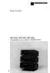
Operating Instructions
VRZ 402, VRZ 403, VRZ 404
HEIDENHAIN Counters
4
Contents
Page
4
4
4
5
5
5
6
6
7
7
1. Berns supplied
2. Brief description-Outline
3. Notes
4. Installation of counter
5. Selection of mains voltage
5.1 Ground screw
6. Stat-ting procedure
6.1 Controls
6.2 Switch-on of counter
6.3 Setup functions
6.3.1 Parameter-entry
;
6.3.2 Parameter Overview
8
9
6.3.2.1 URZ 402
6.3.2.2 URZ 403
6.3.2.3 UR Z 404
10
11
11
11
12
12
6.3.3 Functions/Operating
modes
6.3.3.1 Counting direction
6.3.3.2 mm/inch display
6.3.3.3 Display Step with linear encoders and length gauges
6.3.3.4 Display Step with rotary and angle encoders
6.3.3.5
Function of
q
6.3.3.6 Operating mode Nominal value (NOM)/Maximum
6.3.3.7 Operating mode Display Stop
6.3.3.8 Operating mode Classification
7. Operating
7.1 Zero reset
7.2 Datum set
7.3 Reference mark evaluation REF
7.3.1 Storage of datum Point
7.3.2 Retrieval of correlation Plunger position/Display value
7.3.3 Working without reference mark evaluation REF
8. External operation/Outputs
8.1 Connector layout
8.2 External selection of NOM, MAX, MIN and DIFF
8.3 Storage command
8.4 Signal description of inputs and Outputs
9. Data output
9.1 BCD-data output (URZ 402)
9.1.1 Connector layout
9.1.2 Connection cable
9.1.3 Signal description of inputs and outpuls
9.1.4 Data inquiry
9.1.5 Sign
9.2 U.24/RS-232Cinterface
(URZ 403)
9.2.1 Definition of U.24-inter-face
9.2.2 Transfer rate (baud rate)
9.2.3 Data format
9.2.4 Interruption of data transfer
9.2.5 Data output
9.2.6 Connection of external units (wiring)
9.2.7 Connection cable
9.3 IEEE 488-interface (URZ 404)
9.3.1 Definition
9.3.2 Data format
9.3.3 Control commands
9.3.4 Data transfer
9.3.5 Data output
9.3.6 Addressing
9.3.7 Connection cable, interface cards
9.3.8 Connector layout
9.3.9 Program examples for HP 85
10. Error messages
11. Technical specifications
12. Dimensions
13
-key
(MAX)/Minimum
(MIN)/Difference
(DIFF) display _ 13
16
16
19
19
19
20
20
21
21
22
22
23
23
23
24
24
24
25
25
25
25
26
26
26
27
27
27
29
29
30
30
30
31
31
32
34
34
34
35
36
37
38
3
1. Items supplied
HEIDENHAIN counter VRZ 40X (type as ordered)
Fuse O.lGA/slow-blow, incorporated (for 200. ,240 V)
Fuse 0.315A/slow-blow,
in package (for 100.. ,140 V)
Connector for “extemal Operation”, 12-pole (Ident-No. 22856114)
Connector for BCD-data output, 36-poles (ld.-No. 20073203)
(VRZ 402)
Mains cable
Operating instructions and cenificate of inspection
2. Brief description - Outline
Counters VRZ 402 . . .404 in conjunction with gauges MT 12/25/60/101 constitute a HEIDENHAIN-METRO
digital length
measuring unit.
In addition to the gauges, other HEIDENHAIN linear encoders with 10 um or 20 um grating pitch (e. g. LID 300, LS 703/704,
LS 403/404, ULS 300, etc.) as weil as HEIDENHAIN rotary encoders with sinusoidal output Signals are also suitable for
connection.
The output Signals of the gauges are amplified, interpolated within the counter and subsequently counted in accordance with
the sign. The measured value is displayed via a seven-digit 7-Segment digital display.
The counters are provided with the following
functions:
VRZ 402
VRZ 403
VRZ 404
Data output
BCD
V.241 RS-232-C
IEEE 488
Functions
Zero reset
Datum set
Reference mark evaluation REF
mm/inch calculator
selectable display step
selectable counting direction
Classifying with 2 limit values
Minimum/Maximum
acquisition
Subtraction of Maximum and Minimum
Display stop
External Operation
Output for classifying state
(differente)
3. Notes
Counters VRZ 402
,404 correspond to protection class I of the German VDE provisions VDE 0411 and have been built and
checked in accordance with DIN 57411 part l/VDE 0411 patt 1 “protective measures for electronie measuring units”. In Order to
maintain this condition and to assure safe Operation please adhere to the notes and instructions as contained herein.
Maintenance
These instructions contain all details required for commissioning and Operation of the counters. The units are maintenancefree. In the case of anv fault or failure we recommend return of the counter to our works Traunreut or to your local supplier
Caution!
DO not engage or disengage any connectors
Manufacturer’s
whilst under power.
certificate
We hereby certify that the above unit is radioshielded in accordance with the German official register decree 1046/1984.
The German postal authorities have been notified of the issuance of this unit and have been granted admission for examination
of the series regarding compliance with the regulations.
Information:
If the unit is incorporated by the user into an installation then the complete installation must comply with the above requirements.
4
4. Installation
of counter
The counter is designed as a desk-top unit.
For easier readings it tan be tilted by approx. 14O by means of a collapsible stand. The feet of the unit are provided with M5
tapped holes for fixing to a base plate. Several counters tan be stacked by simply putting one on top of the other. Slipping of
stacked counters is prevented by the housing rim as weil as by small protrusions in the housing cover.
Stacking
Use of tilting stand
5. Selection of mains voltage
Counters VRZ 40X are set to 220 V Operation when supplied. This may be changed to 100, 120, 200, 240 V as follows:
Remove mains fuse holder (Fig. 1) and set voltage selector to the required rating by means of a coin (Fig. 2). Replace mains
fuse holder with correct fuse.
Fuse for 200
240 V 0.16 A slow-blow
Fuse for 100
140 V 0.315 A slow-blow
5.1
Ground screw
To ensure error free Operation when using the external Operation connector the ground screw should be connected to the
ground of the external unit.
5
6. Starting
procedure
6.1
Controls
Digital display
Operating
mode display
Measured value evaluation
I
Transfer of
entry value
Front Panel
MIN
DIFF
MAX
El HEIDENHAIN
:
Keyboard for entry values
and Parameter selection
Reference mark
evaluation
Tilting stand
Clear entry value,
Parameter call and
zero reset of display
\
Mains fuse holder
Mains voltage selector
\
I
Flange socket for external Operation.
Inputs for Zero reset,
Display stop, Min/Max/Difference
selection,
Storage and Measured value evaluation.
Outputs for classifying state
I
Rear Panel
_
Mains switch
Mains’socket
6
Ground screw
l
Data output with VRZ 402 BCD-parallel
VRZ 403 V.24/RS-232-C
VRZ 404 IEEE 488
Flange socket
Gauge
6.2
Switch-on
of counter
The digital display flashes after switch-on (mains switch at counter rear). This signalizes that the displayed value does not correspond to the last selected datum value due to the preceding power interruption.
a) With initial activation the flashing of the display tan be cancelled by pressing the ’ -key twice. The counter is now
Qp
ready for setting the operating mode (see item 6.3).
b) With any further activation
press ’ -key once. The digital display illuminates; flashing of the m
display field requests
Ul
traversing the reference mark of the encoder for retrieval of the last selected correlation between encoder Position and
display value (see item 7.3.2). If this correlatiori is effected via zero reset or datum set after probing of a mechanical limit
stop (reference surface), the
Qp
-key is to be pressed twice (see 7.3.3).
6.3
Setup functions
VRZ 40X is provided with a number of selectable functions
mined by entry of Parameter values.
(see tables as of page 6). The required operating mode is deter-
6.3.1
Parameter-entry
display (e. g.)
Enter Parameter value
Enter value for required operating
mode.
Storing Parameter value
the selected parameter value is stored. The required
operating mode is now set.
Non-volatile
storage of entered Parameter values. When resuming Operation the counter operates in the last entered mode.
7
6.3.2
Parameter Overview
Caution! Different functions are allocated to certain Parameters for the various counters. The functions are described in detail
under 6.3.3
6.3.2.1
VRZ 402
Level of sign at
p negative sign at data interface a LOW level
BCD output
•I negative sign at data interface ” HIGH level
Counting direction
p
positive counting mode with retracting
plunger
q
positive counting mode with extending
plunger
mm/inch conversion
‘2
p display in mm
p display in inch (INCH lights up)
Display Step
displav in mm
‘3
1 displav in inch
p x.xxx5
X.XXl
p X.XXl
Grating period
34
q
I Parameter P4
x.xxxx2
x.xxxx5
x.xxxx5
0
1
0
for encoders with 10 Pm grating period
p for encoders with 20 pm grating period
Blinking display function of the @ key
Function of the
P5
switch-on
p
p
q
1:
1;
1 fault
1:
1;
sets the display
clears the display
and recalls the previous
value
sets the display
to “0”
0 yes
0 no
p
clears the display
and recalls the previous
value
0 no
0 yes
sets the display
to “0”
0 no
0 yes
q
q
P7
clears the display
,“orllstheprevious
p
p
Operating mode
Display blinks after
q
q
q
0
clears the display
fdllsthe
previous
10
1;
13
11
sets the display
display of nominal value (normal counter Operation)
display of smallest value (minimum) of a measurement
series, after pressing m (MIN lights up)
display of largest value (maximum) of a measurement
series, after pressing a (MAX lights up)
display of differente between max. and min. of a
measurement series, after pressing a (DIFF lights up)
p display stop
p classification
(enter limit values in param. P8 and P9)
p display stop/concurrent
q
q
8
display
display stop until next storage command and classificatlon (enter limit values in Parameters P8 and P9)
display,stop/concurrent
display and classification
(enter Iimit values in Parameters P8 and P9)
Lower limit value
‘8
enter numerical value including sign; must be smaller
than upper limit value
Upper limit value
‘9
enter numerical value including sign; must be larger
than lower limit value
Store the selected Parameter value with
q
6.3.2.2
VRZ 403
q +fl
q +o
Outputs additional line
feeds to the data interfacc
between measuring values
PO
Counting
Pl
direction
mm/inch
conversion
P2
Enter number of additional line feeds
00
q
step
P3
Grating
period
P4
Blinking
display
-
function
of the
q
plunger
plunger
display in inch (INCH lights up)
displav in mm
q
q
P5
key
mode with retracting
mode with extending
m display in mm
q
Display
positive counting
positive counting
q
q
q
q
q
q
q
/ displav in inch
for encoders with 10 um grating period
for encoders with 20 um grating period
Function of the
Display blinks after
q W
switch-on
clears the display
and recalls the previous
value
0 yes
0 yes
sets the display
to “0”
0 yes
0 yes
clears the display
and recalls the previous
value
0 yes
0 no
sets the display
to “0”
[9+D
Baud rate
Operating
‘6
mode
‘7
clears the display
and recalls the previous
value
0 no
0 yes
sets the display
to “0”
0 no
0 yes
clears the display
and recalls the previous
value
0 no
0 no
0 no
0 no
13
IlObaud
q
q
300 baud
150 baud
m
600 baud
p
1200 baud
p
2400 baud
p
display of nominal value (normal counter Operation)
q
q
q
p
q
q
q +B
I fault
0 no
•;i sets the display
to “0”
rn+B
I Parameter P4
display of smallest value (minimum) of a measurement
series, after pressing
(MIN lights up)
q
display of largest value (maximum) of a measurement
series, after pressing m (MAX lights up)
display of differente between max. and min. of a
measurement series, after pressing m (DIFF lights up)
display stop
classification
(enter limit values in param. P8 and P9)
display stop/concurrent
display
Lower limit value
‘8
enter numerical value including sign; must be smaller
than upper limit value
Upper limit value
‘9
enter numerical value including sign; must be larger
than lower limit value
Store the selected
Parameter
value with
q
9
6.3.2.3
VRZ 404
Counting direction
mm/inch conversion
Display Step
‘2
q1
positive counting mode with retracting
plunger
p
positive counting mode with extending
plunger
p
display in mm
p
display in inch (INCH lights up)
‘3
n
Grating period
‘4
Blinking display function of the
key
q
0
‘7
q +P
(9+D
0
1
x.xxxx5
x.xxxx5
0
1
Function of the
Display blinks after
q W
switch-on
clears the display
7rllstheprevious
1:
I fault
11;
1:
clears the display
and recalls the previous
value
0 yes
0 no
sets the display
to “0”
0 yes
0 no
clears the display
and recalls the previous
value
sets the display
to “0”
0
clears the display
and recalls the previous
value
sets the display
to “0”
10110
i.yes
0 no
0 yes
0 no
0 no
0 no
0 no
Enter the device address when connecting
IEEE 488 bus.
Entrv values 0 to 30 possible
to an
a
display of nominal value (normal counter Operation)
0
display of smallest value (minimum) of a measurement
series, after pressing
(MIN lights up)
ß
display of largest value (maximum) of a measurement
series, after pressing m (MAX lights up)
ß
display of differente between max. and min. of a
measurement series, after pressing
(DIFF lights up)
0
display stop
q
classification
a
display stop/concurrent
q
q
(enter limit values in param. P8 and P9)
display
Lower limit value
P8
enter numerical value including sign; must be smaller
than upper limit value
Upper limit value
P9
enter numerical value including sign; must be larger
than lower limit value
Store the selected Parameter value with
* only with rotary and angle encoders
IO
11;
sets the display
0
q
Operating mode
x.xxxx2
x.xxxx5
for encoders with 20 um grating period
q
q +ß
x.xxx5
X.xxl
for encoders with 10 um grating period
q
q
‘6
Parameter P4
q
q
Device address
display in inch
p
‘5
q +ß
display in mm
q
6.3.3
Functions/Operating
modes
6.3.3.1
Counting direction
The positive counting mode may be allocated either to the retracting or the extending
entry of Parameter value Pl.
plunger. Switch-over
- 0.0010
mm
- 0.0010
mm
is effected via
- 0.0005 mm
0.0010
mm etc.
6.3.3.2
mm/inch display
Optional display of measured value in either “mm” or “inch”. Selection effected via value entry in Parameter P2. This is also
possible during measuring.
Parameter
Parameter value
Display
Unit
P2
0
25.4000
mm
P2
1
1 .ooooo
inch
INCH illuminates
11
6.3.3.3
Display Step with linear encoders and length gauges
l
I
Signal period
Measuring System
Display Step
mm
/
Metro300,
ULS
length
LID gauge
311,
LID 351, LS 101, LS 405
10 um
I
20 um
LS 303, LS 603, LS 403,
LS 406, LS 704, LS 107
0.001
0.0005
I
inch
/
0.00005
0.00002
I
0.00005
0.001
Parameter setup
P3
P4
01
0
I
0
1
6.3.3.4
Display Step with rotary and angle encoders
Rotary encoder
Line number
Display step
Parameter setup
P4
P2
P3
ROD 700/800
ER0 7251815
36 000
o,ooo5°
0,001 o
0
0
0
1
0
0
ROD 250/700
RON 2551705
ER0 725/815
18000
0,001 o
0
0
1
0,Ol IJ*
0
1
1
ROD 450/456 *
MINIROD 450
1800”
* only possible with VRZ 404
Rotary and angle encoders tan also be used to determine lengths, travels and feedrates. For this purpose, the transmission
ratio (rack/pinion), lead screw or friction wheel must be taken into account in addition to Parameters P3 and P4.
12
6.3.3.5
Function of
m
/
-key
Various functions tan be assigned to the
-key via Parameter Pl: Parameter cal1 and Clearing of the entry value or zeroing
m
the displav.
Parameter Pl also permits a deactivation of display blinking after interruption in power and/or switch-on or due to malfunction.
Parameter
Parameter value
Function of the CL key
P5
0
clears the display and recalls the
previous value
0 yes
0 yes
1
sets the display to “0”
0 yes
0 yes
2
clears the display and recalls the
previous value
0 yes
0 no
3
4
sets the display to “0”
0 yes
0 no
clears the display and recalls the
previous value
0 no
0 yes
5
6
sets the display to “0”
0 no
0 yes
clears the display and recalls the
previous value
0 no
0 no
7
sets the display to “0”
0 no
0 no
6.3.3.6
Operating mode Nominal value (NOM)/Maximum
Measured value evaluation
In this operating
(MAX)/Minimum
Display blinks after
switch-on
fault
(MIN)/Difference
(DIFF) display.
not started:
mode (Parameter value P7 = 0/1/2/3/4)
the counter display is simultaneous
with each plunger position.
Measured value evaluation started:
From any number of measured values, the largest (Maximum) and the smallest (Minimum) value is determined and the
differente then calculated.
These values tan be transferred into the display in succession via Parameter switch-over or external Operation. After the next
star-ting of the measured value evaluation a new maximum and minimum is determined.
The maximum and minimum acquisition is carried out every 520 us. Intermediate Maxima/Minima
are not recognized. The
test piece therefore must be moved at such a slow rate that the measured value Change within the 520 us is smaller than the
required accuracy, e.g. with a required accuracy of f 0.5 um the maximum plunger movement must not exceed
1 mm/s.
Start of measured value evaluation:
The measured value evaluation is started either by pressing the Start-key or via external Operation (See item 8) by TTL pulse
trigger or make contact.
Caution: with started measured value evaluation the data output is delayed (See item 9 Signal diagrams)
Measured value evaluation tan be cleared by:
mains off/on
. switching INT/EXT (See item 8.2)
. switching to operating mode classification or display stop
IEEE bus commands DCL/SDC with VRZ 404
Selection of display:
Selection between display of Nominal/Maximum/Minimum
and Differente value is effected either by entry of the Parameter
value or via external Operation by TTL pulse trigger (LOW level) or make contact (also see item 8.2).
Selection of display via
NOM
MIN
MAX
DIFF
entry of Parameter value in Parameter P7
P7 = 0
P7=1
P7=2
P7=3
external Operation
(LOW level/O V) at
PIN 1
PIN l+
PIN 6
PIN l+
PIN 8
PIN l+
PIN 7
13
Application
examples
A random number of Points may be probed on the measuring Object. Subsequently,
and the Differente between both values (DIFF) tan be displayed and output.
Straightness
Flatness
the Maximum
=
:
MIN
Roundness
0
Maximum
MAX
Minimum
MIN
ConcMtricityf
Eccentricity
2e
e -
=
rMAX
DIFF
2
-
rMIN
(MAX), the Minimum
(MIN)
Wobble
Stroke
f
measulemcgnt
Slide
[roke
minimum
k DlFF\
stroke Position
MIN
maximum
stroke Position
MAX
Shaft diameter measurement
When pushing the round test piece through, the display Stops (without the usual back and forth trials) at the maximum value
(operating mode Maximum display) which corresponds to the diameter.
A
Measuring
Maximum
roller
MAX k shaft DIA
15
6.3.3.7
Operating mode Display Stop
In operating modes Display Stop, the display may be stopped for any length of time. The internal counter continues Operation.
The Display Stop is activated by applying a storage command (see 8.3). Data output is initiated simultaneously.
Caution!
If no data are called up with counters VRZ 403 and VRZ 404 (e. g. no subsequent
electroncis
Error 2 is indicated (see item 10). This error message may be cleared by pressing
m
again.
unit connected),
error message
until the counter is switched on once
Display stop
In operating mode Display Stop (Parameter P7 = 4). the display is always set to the updated measured value via a storage
command. Display remains stopped until the next storage command updates the display once again.
A clocked display tan be realized via connection of an external clock generator.
I
Plunger
Position [um]
0
Storage command
1
Display value with
P7=4
00000000000000~~~~~~~~~~~~~~~~~000
00000000000000~~~~~~~~~~~~~~~~~~~~
0000000000000000000000000000000000
Display value with
0000~uluzba3cn0-~
Display stop
5
10
15
20
25
I I I I : I : : : : I : : : : I : : : I 1::
30
: : 1:
:,
0’ 0 0 0 0’ 0’ 0 0 0 0 0 0 0 0’ 0’ 0 0 0 0 0 0 0 0 0 0 0 0’ 0 0’ 0 0’ 0 0 0
~bbbbbbbbb~b~~~~~OOO0
0000000000---~~-------~~~~~~~~~~~~
0000000000000000000000000000000000
P7=6
Display stop/
0 0’ 0’ Cs 0 0’ 0 0’ 0 0 0’ 0’ 0 0 0 0’ 0 0’ 0’ 0 0’ 0’ 0 0 0’ 0’ 0’ 0 0’ 0 Cs 0 0’ 0’
simultaneous
display
Display Stopkoncurrent
display
If Parameter value P7 = 6 is entered, display is stopped for the duration of the storage command
the storage command the display continues again with the updated measured value.
(see item 8.3). At the end of
6.3.3.8
Operating mode Classification
In operating mode Classification
(Parameter value P7 = 5) two limit values tan be entered via Parameter P8 and P9.
Parameter
Description
Exampel 1
Example 2
P8
P9
lower limit value
upper limit value
25.9920
26.0130
-
14.0035
13.9955
The classifying state, i.e. whether the updated measured value falls within the stored limit values or exceeds these, is indicated via Symbols and output via 2 lines (flange socket for external Operation, see item 8).
The max. lag time between exceeding the preset limit values and the output of the corresponding
mm-display:
8 ms
inch-display: 20 ms
Symbol
Signals at Pin 4/5 is for
Classifying state
Output Signal
PIN 4
PIN 5
HIGH-level
HIGH-level
Measured value within tolerante
<
HIGH-level
LOW-level
Measured value smaller than
lower limit value
>
LOW-level
HIGH-level
Measured value larger than
upper limit value
The levels of the output Signals correspond
LOW-level: = 0.4 V at I - 12 mA
HIGH-level: = 2.4 V at sink
- = - 2.6 mA
Source
to TTL (Low Power Schottky)
Load capacity: fsink= 12 mA lsource= - 2.6 mA
16
App,ication
examp,&i
,” t”““x%:-
ClassifyingJSorting
Nominal
dimension
26
+ 0,012
- 0,008
1.0236
: ;;;;;:
..--.
Actual dimension,
within tolerante
(wo4
oversized
(rework)
/
-/ r l-l r-1r-r r
i1 1l.J 11111 I/
\
-
undersized
(reject)
l
Counter with 2 cutoff Points
Cutoff Point 1
e.g. - 25 mm (.984 in)
Cutoff Point 2
e.g. + 25 mm (.984 in)
Travel
----i
i
The gauge serves as linear encoder. The values of cutoff Points 1 and 2 are to be entered into Parameter P8 and P9 of the
counfer in the correct correlation. Via a customer-specific
control electronics unit the drive of the carriage is switched off
upon reaching one of the cutoff Points.
Counter with deceleration
Cutoff Point, e.g. 50.0000
Point and cutoff Point
mm
Deceleration Point, e.g.
48.0000 mm (1.8898 in)
Feed rate is reduced upon reaching the deceleration
18
Point in Order to assure safe stopping
at the cutoff Point.
7. Operation
7.1
Zero reset
Counter tan be reset to zero at any
random location of the travel.
Press
I
P
0-key
b
SET on
Zero appears on left of display.
b
SET off
Zero as datum appears on right
of display.
i
q
Transfer key
SET
or, if Parameter P5 = 1/3/5/7 has been addressed.
m
Clear key
Counters VRZ 402/403/404
effected via the IEEE bus.
b
t-11-1
I-ll-l1-1
Zero appears in display upon
release of key.
1-.-ff
II - II - II - I
I
may also be zeroed via external Operation (see item 8). With VRZ 404 zeroing tan also be
7.2
Datum set
Any random number (e. g. the Nominal
dimensions) tan be set as reference
datum (initial value).
Press
Ewu
Enter datum
e.g. 80.001 mm
(3.150 in)
SET on
Value appears on left of display
I-I r-1 1-11-1
-l-llIrr~l
- -.-
I
I
SET
Clear key for wrong entry
111 I-I I-l l-l
~Illllll
- -.-
Entry of neg. sign after
datum set, if reqd.
Transfer key
I
I
SET
b
SET off
Datum value e.g. 80.001 mm (3.150 in)
appears on right of display
15 l-i l-l t-1
IJ lJ,lJ
IJ
l I-I
IIJ
19
The datum value is rounded off in accordance with selected display Step and mm or inch display.
entered
datum value
(last decade)
transferred
datum
with display step
0.0005
mm
value
(last decade)
0.001 mm
0.00002
0
0
0
0
0
5
5
5
5
5
inch
0
0
2
2
4
4
6
6
8
8
0.00005
inch
0
0
0
0
0
5
5
5
5
5
7.3
Reference mark evaluation
REF
The correlation between plunger Position and display value last effected by means of zeroing or datum set in function REF
(REF illuminates), tan be easily retrieved after power failure with the reference mark evaluation REF by passing over the gauge
reference mark. The reference mark evaluation REF is not possible in operating modes Maximum, Minimum and Differente
display (Parameter P7 = 1/2/3).
7.3.1
Storage
of datum
Point
Press
REF key
traverse over reference mark
(location see operating instructions
of gauge)
Zero reset or datum set
(See 7.V7.2)
20
Display Stops
REF flashes
b
Display concurrent
REF on
7.3.2
Retrieval of correlation
II
Q
9
0
Cl
I
I
Plunger position/Display
value
1
switch on counter
b
REF dark
Display flashes
press REF
b
REF flashes
Display Stops
I
pass over reference mark
(location see operating instructions
of gauge)
Display simultaneous
REF on
Display value is now referenced to the last datum set in REF Operation
7.3.3
Working without
reference mark evaluation REF
Some applications provide a fixed mechanical limit stop as reference plane. In these cases the reference mark evaluation is
not required. It tan easily be disabled by pressing the REF-key twice after counter switch-on. The reference System tan be
retrieved by probing the measuring table surface, a master piece, and zeroing or datum set.
21
8. External operation/Outputs
The 12-pole flange socket at counter rear serves for external Operation and for output of ciassifying Signals.
The following functions tan be operated externally:
Zero reset (sec item 7.1)
Display stop (See item 6.3.3.7)
Storage/Data output (see item 8.3)
Minimum display (see item 6.3.3.6)
Maximum display (see item 6.3.3.6)
Differente display (see item 6.3.3.6)
Start Measured value evaluation (see item 6.3.3.6)
Extemal Operation is also possible via make contact or TTL pulse trigger. The connection
surface contact between connector and shield should be ensured.
In the following
cable must be shielded. A broad
diagram, inputs of the counter are designated with “E”, Outputs with 74”.
8.1
Connector layout
_l----
Contact
designation
----_
--‘-_----_
-
_-
_-
_-
_-
_ -_
-
,
1
z
;j
4
w
w
W
6
5
a
6
7
8
W
w
w
9
10
11
w
W
ov
Duration of
L15ms
:onnector, 12-pole
J.No. 20072003
i
I
Pulse trigger
22
uwith
/
TTL-level
a,
ol
2 1 ps
VRZ 404
I
I
12
l
8.2
External selection of NOM. MAX, MIN and DIFF
Display of Nominal value (NOM), Maximum (MAX), Minimum (MIN) or Differente (DIFF) tan be selected via Parameter entry
(Parameter value P7 = 0/1/2/3) or via external Operation. Selection via external Operation is only possible if the counter is set to
one of those four operating modes. Via PIN 1 it is determined whether selection is effected via Parameter entry (INT) or
external Operation (EXT).
Input
Wiring
Designation
PIN 1
LOW-level/OV
External Operation (EXT)
HIGH-level/open
Parameter entry (INT)
With PIN 1 on LOW-level/O V, display of NOM, MAX, MIN or DIFF value tan be externally operated.
Display selection with 4-step switch
MAX
PIN 8
PIN 11
0”
a+.
I
1
Display selection with lTL level
PIN
1Function
Parameter entry INT possible
External Operation INT possible
Nominal value NOM
Minimum
MIN
Maximum
MAX
Differente
DIFF
6
7
8
X
X
X
H
H
H
H
H
H
L
H
L
H
H
L
8.3
Storage command
At PIN 10 and PIN 12 the storage commands
mit.
tan be entered via make contact or pulse trigger for activation of the data out-
In operating mode “Display stop” (Parameter value P7 = 4/6) the storage command
display and setting to updated measured value.
Connection
Function
PIN 10
Storage via make contact
is simultaneously
used for “freezing” of the
Level
Duration
active LOWJ
hl5
ms
21
ps
i
PIN 12
8.4
Signal description
Storage via pulse trigger
lactive
Lowf-
of inputs and Outputs
Inputs (PIN 1/2/3/6/7/8/10/12),
LOW active
LOW-level UeL 5 0.4 V at Isink- 0.2 mA
HIGH-level U+ 2 2.7 V at IsO,,rCe
20 uA
Outputs (PIN 4/5) (TTL compatible)
LOW-level UaL 5 0.4 V
HIGH-level UaH B 2.4 V
load capacity laL = 12 mA
laH= - 2.5 mA
Note:
Inputs and Outputs may only be connected
VDE 0100/5.73 § 8.
to circuits with protective low voltage as per German Standard
23
9. Data output
The counters are provided with different data Outputs:
VRZ 402 BCD data output
VRZ 403 V.24/RS-232-C-interface
VRZ 404 IEEE 488-interface
9.1
BCD-data output (VFL? 402)
Parallel data output in 8-4-2-I-BCD-Code
9.1.1
Connector
layout
PIN
PIN
PIN
PIN
1
2
3
4
2’
2’
2’
23
A
A
A
A
Decade 1
PIN
PIN
PIN
PIN
5
6
7
8
2’
2’
2’
23
A
A
A
A
Decade 2
PIN
PIN
PIN
PIN
9
10
11
12
2’
2’
2’
23
A
A
A
A
Decade 3
PIN
PIN
PIN
PIN
13
14
15
16
2’
2’
2*
23
A
A
A
A
Decade 4
PIN
PIN
PIN
PIN
17
18
19
20
2’
2’
2*
23
A
A
A
A
Decade 5
PIN
PIN
PIN
PIN
21
22
23
24
2’
2’
2*
23
A
A
A
A
Decade 6
PIN
PIN
PIN
PIN
25
26
28
27
2’
2’
23
2*
A
A
A
A
PIN
PIN
PIN
PIN
29
30
31
32
A
E
E
A
Sign (polarity selectable, see item 9.1.5)
“Storage” via pulse trigger t L 1 us
“Storage” via make contact t L 15 ms
t=20
us
Printer release pulse
PIN
PIN
PIN
PIN
33
34
35
36
A
error message” (HIGH active)
shield
vacant
ov
Decade7
* in case of power interruption,
was exceeded
24
(TTL-level) at 36-pole Amphenol-Tuchel-socket.
2
contamination
of scale, Error 1, Character overflow, or if maximum
input frequency
9.1.2
Connection cable
A shielded
cable
is to be used for connection
to the BCD-output
(e. g. cable LiYCY 40 x 0.14 mm2, Id.-No.
max. cable length should not exceed 10 m (32.89 ft). The mating connector
57-30360) is included in delivery.
9.13
Signal description
ld.-No. 20073203
20242001).
The
(Amphenol Tuchel
of inputs and Outputs
Inputs (negative logic)
Storage via pulse trigger
TTL-level
-pJ-
tz1us
Storage via make contact
Make contact
t L 15 ms
Outputs (TTL compatible)
Decade 1. .7 and sign (positive logic)
LOW-level UaL 5 0,4 V at isink = 12 mA (max.)
HIGH-level UaH L 2,4 V at Isource= - 2.6 mA (max.)
Printer release pulse/Error message:
LOW-level UaL IO.4 V at Isink = 4 mA
HIGH-level UaH L 2.4 V at IsourcB= - 0.4 mA
Load capacity laL= 8 mA
laH= - 0.4 mA
9.1.4
Data inquiry
Data output is parallel in 8-4-2-I-BCD-Code
via incorporated intermediate memory. When applying a storage command
(leading edge) via external Operation or to the BCD data output, the updated display value (Nominal measured value,
Minimum, Maximum or Differente) is transferred into the intermediate memory after a max. deiay of tI. After the data have
been registered in this buffer memory, the VRZ 402 issues a Printer release pulse (Ready-message). This pulse indicates
counter at standby for data output to the subsequent electronics (Printer, calculator etc.).
The Printer release pulse has a fixed duration of 20 us. Even after expiration of this pulse the data are retained in the buffer
memory until the next storage command. A new storage command tan be entered immediately after the trailing edge of the
Printer release pulse.
Storage command
---g---p
Actual storage
Printer release pulse
for storage via:
pulse
make
pulse
make
tE 2 1 ps
215 ms
tq 2 0.8 ps
55ms
mm-display
trigger
contact
trigger
contact
inch-display
t2s10ms
532 ms
5 25 ms in operating mode (NOM (P7 = O)/Display stop (P7 = 4/6)/Classifying
(P7 = 5)
5 112 ms in operating mode NOM/MIN/MAX/DIFF
(P7 = 0/1/2/3) after Start of
Measured value evaluation
t3 > 10 ps
9.1.5
Sign
The Signal level corresponding
to the negative sign tan be converted via Parameter entry,
Parameter
Parameter value
Sign
Level
PO
0
- (negative sign)
LOW-level
PO
1
- (negative sign)
HIGH-level
25
9.2
V.24/RS-232Gintetface
(VRZ 403)
WZ 403 is provided with a Standard interface “V.24” as per CCITT recommendation
or RS-232-C
9.2.1
Definition
of V.24-interface
The following important criteria are provided because units with different Signal levels, connector
as ,,V.24-compatible Systems”.
as per EIA-Standard.
layouts etc. are on the market
Voltage-compatible
interface
The V.24 interface processes Signals with voltage levels. Current interfaces (e. g. 20 mA) cannot be connected!
Signal
designations
and levels
1 Signal
1 Meaning
I
Data Signals:
TXD”
RXD”
Transmit Data
Receive Data
Control Signals:
DTR
RTS
Data Terminal Ready
Request to Send
Verification Signals:
DSR
CTS
Data Set Ready
Clear to Send
Logic-level
“l”:-3v...-15v
“0”: + 3 v..
Operating
level
-5v...-l5V
+ 5 v.. + 15 v
+ 15 v
* Designations “TXD, RXD” are derived through negative level for “1’:
Series data transfer
The V.24-interface of VRZ 403 transmits data in series. Units with parallel interfaces cannot be connected!
Transfer code
The code being used is ASCII with additional “Even parity bit’: This corresponds
exceptions.
SXT: Start of data transfer
DC3: interruption of data transfer
DCI : continuation of data transfer
to the ISO-Code with the following
9.2.2
Transfer rate (baud-rate)
The baud-rate signifies the number of bits which tan be transmitted every second. The V.24-interface of VRZ 403 permits the
following baud rates: 110,150, 300, 600, 1200, 2400.
Peripheral units must be able to process the selected baud-rate without limitations in Order to prevent data transmission errors
The baud-rate tan be selected via Parameter entry.
Parameter
P6
P6
P6
P6
P6
P6
26
Parameter
value
Baud-rate
110
150
300
600
1200
2400
baud
baud
baud
baud
baud
baud
9.2.3
Data format
The individual characters comprise
Start-Bit
7 Data-Bits
Even-ParityBit
2 Stop-Bits
Sequence of Character output
1-123.4565?1
t
J
I
Sign (-)
Decade 7
Decade 6
Decade 5
Decimal Point (at correct place)
Decade 4
Decade 3
Decade 2
Decade 1
Unit/Fault message (? if fault)
(Empty space if mm, II if inch)
“Carriage return” (CR)
“Line feed” (LF) (number selectable)
The number of additional “line feed” commands
(blank lines) is selectable between 0 and 99 via Parameter entry.
Parameter
Parameter value
Description
PO
e. g. PO
PO
X
x = number of additional blank lines LF
one additional line feed between 2 printouts (2xLF)
five additional line feeds between 2 printouts (6xLF)
9.2.4
Interruption
1
5
of data transfer
With normal commercially available data receivers (e. g. Printers) it is possible that data transfer has to be interrupted from
time to time (e. g. printing procedure or “overflow” of Character memory). Therefore, a Signal is produced for interruption/
continuation of data transfer. The technical features vary depending on the make.
a) Start/Stop Signals via interface input RXD
The data receiver controls the VRZ 403 via the ASCII characters DC3 and DCI;
DC3 = XOFF = CTRL S: interruption of data transfer.
DCI = XON = CTRL 0: continuation of data transfer.
Owing to the Signal switching times, up to four characters tan be transmitted after output of the Stop Character DC3.
b) Start/Stop Signals via the interface input CTS
In this case the data receiver converts the level of the verification input CTS of the transmitter interface, whereby the level
depends on the make.
9.2.5
Data output
Data output is effected via a built-in intermediate (buffer) memory.
When a storage command is given (leading edge) via extemal Operation or control Character Control B (= STX) to the V.241
RS-232-C interface, the updated display value (Nominal measured value, Minimum, Maximum or Differente) is transferred to
the intermediate memory.
After a delay t2 the data are provided at the interface output TXD. The duration of data transfer is dependent on the
selected baud rate and the required number of line feeds (LF).
Caution:
For the storage command
via external Operation, TTL-level is valid, not V.24-level!
27
1
Signal
Storage
diagrams
for the simplified
via external
connector
layout
Operation
Storage command
E
Actual storage
DSR/DTR
RTS/CTS
tE L 1 ps
115 ms
t, 5 0.8 ps
5 5 ms
mm-display
t2115ms
530 ms
via V.24IRS
-
t2
t3
-
inch-display
5 37 ms in operating mode (NOM (P7 = O)/Display stop (P7= 04/6)/Classifying
(P7 = 5)
5 118 ms in operating mode NOM/MIN/MAX/DIFF
(P7 = 0/1/2/3) after statt of
Measured value evaluation
t3 > 10 ps
Storage
/////////
TXD
for storage via:
pulse trigger
make contact
pulse trigger
make contact
232-C-interface
-
RXD
r
Control B
1
actual storage
DSR/DTR
RTS/CTS
//////m-.
TXD
mm-display
tl 510 ms
5 21 ms
t2 5 10 ms
421 ms
t3 h 10 ps
28
inch-display
5 17 ms in operating
5 62 ms in operating
Measured
5 17 ms in operating
$60 ms in operating
Measured
t2
mode
mode
value
mode
mode
value
t3
NOM (P7 = O)/Display
NOM/MIN/MAX/DIFF
evaluation
NOM (P7 = 0) Display
NOM/MIN/MAX/DIFF
evaluation
stop (P7 = 4/6)/Classifying
(P7 = 5)
display stop (P7 = 0/1/2/3) after statt
of
stop (P7 = 4/6)/Classifying
(P7 = 5)
display stop (P7 = 0/1/2/3) after Start of
9.2.6
Connection of external units (wiring)
Depending on the type of the employed data units, different wiring of the connection
Standard connector layouts are being used.
cables might be required. Some non-
Commonly used wiring:
Complete wiring
V.24 connection
of VRZ 403
CHASSIS
SIGNAL
external unit
GND
TXD
RXD
RTS
CTS
DSR
GND
DTR
CHASSIS
SIGNAL
GND
TXD
RXD
RTS
CTS
DSR
GND
DTR
Signals RTS, CTS, DSR and
DTR must have operating level “1”
(+ 5
+ 15 V) for data transfer-.
Simplified wiring
V.24 connection
of VRZ 403
CHASSIS
SIGNAL
GND
TXD
RXD
RTS
CTS
DSR
GND
DTR
1
2
3
4
5
6
7
20
0
0
0
external unit
0
=
=
0
0
0
0
0
FEi---
0
1
2
3
4
5
6
7
20
CHASSIS
SIGNAL
GND
TXD
RXD
RTS
CTS
DSR
GND
DTR
Signals RTS, CTS, DSR and
DTR constantly have working
level “1” (+ 5
+ 15 V) due
to bridges 415 and 6120.
9.2.7
Connection cable
To ensure error free data transmission
Min-D connectors, ld.-No. 242869.,
we recommend
you use the HEIDENHAIN
data transmission
cable with 25 pin Sub-
29
9.3
IEEE 488-interface
(VRZ 404)
Data output of VRZ 404 corresponds to “IEEE 488” and the “ANSI-Standard
with the exception of the different connector System.
MC 1.1”. It is identical to the IEC 625 Standard
9.3.1
Definition
Level
The levels of the interface lines correspond
HIGH-level UH L 2.0 V
LOW-level UH $0.8 V
to IEEE 488/ANSI-Standard
MC l.l/IEC 625
Output Stage
The output Stage consists of Open-Collector-Drivers
Interface functions
The VRZ 404 is a “Listener/Talker”,
i.e. it tan transmit data and also receive commands.
T6
Talker
Serial Polling
Automatic Address Clear when My Listener Address (M LA) is set
L4
Listener
Automatic
lt has the following
interface functions.
Address Clear when My Talker Address (MTA) is set
SH 1
Talker Handshake function provided
AH 1
Listener Handshake function
SR 1
Service Request function provided
DC 1
Device Clear and Selected Device Clear provided
DT1
Trigger facility with Group Execute Trigger (GET)
El
Open-Collector-Drivers
provided
With Group Execute Trigger (GET) the updated display value is transferred into the incorporated buffer memory and at
standby for polling.
The interface functions Device Clear (DCL) and Selected Device Clear (SDC) operate identical to Zero reset or Extemal
zero reset.
Caution:
The Talker function T6 indicates that the VRZ 404 cannot operate in mode “Talker only”. A Controller must always be provided
in the System. Connection of only one Printer to VRZ 404 is therefore not possible.
Transfer Code
ASCII code is used for data transfer-.
9.3.2
Data format
Transfer of the indicated value is effected bit-parallel/byte-serial.
Character
1
2
3
4
5
6
7
8
9
IO
1-123
1
Sign
Decade 7
.4565
Decade 3
Decade 1
Unit (blank with
( ” with
or fault detection
11 “Carriage return”
12 “Line feed” (LF)
mm)
inch)
Signal (? with error message)
(CR)
(number selectable)
With the last Character the control command
30
The VRZ provides 12 characters in sequence:
EOI (@-rd Qr Jdentify) is simultaneously
output
9.3.3
Control commands (Management-Bus)
VRZ 404 tan process or generate the following
ATN (Attention)
IFC (Interface Clear)
EOI (End Or Identify)
SRQ (Service Request)
The control command
REN (Remote Enable)
is not recognized by VRZ 404.
control commands:
9.3.4
Data transfer
Data transfer is carried out via 3-Line-Handshake
process. The 3 Handshake lines have the following
DAV Data Valid;
operated via Talker or Controller and indicates in active state
(LOW) that data are at standby.
NRFD Not Ready for Data
operated via all active Listeners
NDAC Not Data Accepted
operated via all active
Listeners.
meaning
31
9.3.5
Data output
Data output is effected via the incorporated
intermediate
memory.
The updated display value is transferred into intermediate memory after:
a) Entering a storage command
The storage command (TTL pulse trigger or make contact) is applied at the input for external Operation (see item 8.3). The
counter stores the value after a delay tl and then immediately (delay t2) provides the control command Service Request
(SQR). For the subsequently carried out Serial Polling of the Controller, the following sequence of the interface messages is
required (see IEEE 488/IEC 625):
ATN
1
1
UNL
SPE
(TA4 N
SBN or
SBA
1
1
SPD
UNT
Unlisten
Serial Poll Enable
Clear of anv active Listener
Start of Serial Polling
Talkaddress
Status Byte not active
Status Byte active
Talker Address of unit N
Serial Poll disable
Untalk
End of Serial Polling
Clear of last active Talker
Status Byte of unit N
Caution: the interface message Serial Polling (SPE) must be provided Prior to setting of the Talker Address (TAD)
The VRZ 404 emits the following
Bit Pattern
hex
dec
Status Character SBA
01000001
41
65
Service Request is only reset after Seriai Polling.
VRZ 404 commences data output with a delay t4 after recognition of My Talker Address (TAD = MTA).
Between Service Request SRQ and standby of data at the interface, a max. delay t3 Passes. If in the meantime the Serial Polling has been completed and the Talker Address set, the line DAV (Data Valid) will subsequently become active.
Signal
diagram
Storage command
E
Actual storage
t1
--SRQ
A
-IEEE-Bus
DAV
t2
Serial Poll j-l
TAD/MTA
Byte
1
Byte
2
Byte
3
A
with
storage
via:
tE 2 1 1s
L
32
tE 2 15 ms
tl d 0.8 ps
tt 55 ms
tl d 0.3 ms
make contact
pulse trigger
make contact
mm-display
t2 5 0.28 ms
ts approx. 11 ms
t2 5 0.58 ms
t3 approx. 35 ms
inch-display
approx. 25 ms in operating mode NOM (P7 = O)/display stop (P7 = 4/6)/Classifying
approx. 115 ms in operating mode NOM/MIN/MAX/DIFF
Measured value evaluation
(P7 = 0/1/2/3)
after statt
(P7 = 5)
of
b) Bus Command GET
The Bus Command GET effects simultaneous storage with all VRZ 404 addressed. With recognition of GET the Handshake line
NDAC is activated until the data are at standby for output (t2). Only then tan the appropriate Talker Address TAD be set.
VRZ 404 commences
(TAD = MTA).
data output with the delay ts after recognition
of My Talker Address
GET
TAD/MTA
Signal diagram
IEEE-Bus
Actual storage
N DAC
A
12
A
DAV
mm-display
inch-display
I 25 ms in operating mode NOM (PI = O)/display stop (P7 = 4/6)/Classifying
(P7 = 5)
5 115 ms in operatingmode NOM/MIN/MAX/DIFF
(P7 = 0/1/2/3) after start of
t2$10ms
$35 ms
Measured value evaluation
t3 5 0.4 ms
c) Receipt of My Talker Address (MTA)
After recognition of My Talker Address (MTA), the updated value will be stored unless the counter has received a Prior storage
command or GET command. VRZ 404 commences data output with the delay t2 following actual storage.
Signal diagram
IEEE-Bus
p
TAD/MTA
I-
Actual storage
A
N DAC
I
DAV
I
I
A
t2
tt 5 200 ps
500 us
mm-display
t,SlO
435
ms
ms
/
Measured value evaluation not started
after Start of Measured value evaluation
inch-display
S 25 ms in operating mode NOM (P7 = O)/display stop (P7 = 4/6)/Classifying
(P7 = 5)
S 115 ms in operating mode NOM/MIN/MAX/DIFF
(P7 = 0/1/2/3) after Start of
Measured value evaluation
9.3.6
Addressing
In Order to enable controlled data exchange between several units, the units connected
provided with addresses.
to the IEEE 488 bus must be
Determination of the unit address of VRZ 404 is carried out via entry of the Parameter value in
Parameter P6.
Parameter
Parameter
P6
e.g. P6
P6
X
value
Description
x = unit address (0 to 30 possible)
VRZ 404 has address 5
VRZ 404 has address 21
5
21
9.3.7
Connection
cable, intetface cards
In Order to ensure failsafe Operation use a shielded cable with metallic connector housing. In addition to PIN 12 the shield
should also be connected to the connector housing. The total length of the connection cables of all units (max. 15) connected
to the IEEE 488-bus may not exceed 20 m. The max. cable length between two units is 2 m. Remote distances require the
use of so-called bus extenders (modern Operation, if reqd.). A number of companies, e. g. Hewlett Packard, which specialize in
interface accessories, offer suitable units and completely wired connection cables.
9.3.8
Connector
layout
Connector layout is standardized as per IEEE 488/ANSI-Standard
nection to IEC-625-bus Systems is also possible.
PIN
PIN
PIN
PIN
PIN
PIN
PIN
PIN
34
1 DIO 1 Data input/output 1
2DI0 2Data input/output 2
3 DIO 3 Data input/output 3
4 DIO 4 Data input/output 4
5EOI End Or Identify
6 DAV Data Valid
7 NRFD Not Ready for Data
8 NDACNot Data Accepted
PIN
PIN
PIN
PIN
PIN
PIN
PIN
PIN
MC 1.1. By means of a regular adapter connector/cable,
9 IFC Interface Clear
IOSRQ Service Request
11 ATN Attention
12Shield
13 DIO 5 Data input/output
14 DIO 6 Data input/output
15 DIO 7 Data input/output
16 DIO 8 Data input/output
5
6
7
8
PIN
PIN
PIN
PIN
PIN
PIN
PIN
PIN
17
18
19
20
21
22
23
24
REN Remote Enable
Ground OV twisted with
Ground OV twisted with
Ground OV twisted with
Ground OV twisted with
Ground OV twisted with
Ground OV twisted with
Logic Ground OV
con-
PIN
PIN
PIN
PIN
PIN
PIN
6
7
8
9
10
11
9.3.9
Program examples for HP 85
The program examples for HP 85 are in Basic. For VRZ 404 the unit address “6” or with two connected VRZ 404 the
addresses “5” and “6” have been selected.
The Select Code for the HP-IB Interface is “7”.
Interface messages (Bus commands)
Interface Clear (IFC)
Device Clear (DCL)
Selected Device Clear (SDC)
Group Execute Trigger (GET)
ABORT10 7
CLEAR 7
CLEAR 706
TRIGGER 706
Data inquiry
a) by setting the Talker Address
ENTER 706 ; AS
DISP A$
VRZ 404 (Address 6) is addressed as Talker; value stored
and transferred.
value is displayed
b) with Group Execute Trigger (GET)
one VRZ 404 connected
TRIGGER 706
ENTER 706 ; A$
DISP A$
storage with GET
addressing, data inquiry and display
two VRZ 404 connected
TRIGGER 705,706@
RESUME 7
storage from unit 5 and 6 with GET
DISP “VRZ 404 516”
ENTER 705 ; A$
addressing, data inquiry and display unit 5
DISP A$
ENTER 706 ; A$
addressing, data inquiry and display unit 6
DISPA$
If more than two units are connected, then the program tan be amended accordingly
c) with storage via external Operation
With Serial Polling to be carried out following Service Request (SRQ), the interface message SPE must be effected before setting of the Talker Address (TAD) (see item 9.3.6). The Basic command SPOLL (6) is therefore not suitable for Serial Polling with
HP 85. Serial Polling must thus be formulated by the User, e.g. as subprogram “SUB 100”.
100 SEND 7 ; UNL MLA
110 SEND 7 ; CMD CHR$ (24)
120 SEND 7 ; TALK 6
130 RESUME 7
140 ENTER 7 USING II # , B”; S6
150 SEND 7 ; CMD CHR$(25)
160SEND7;UNT
170 RESUME 7
180 RETURN
If several units are to be operated via Serial Polling, the program
priate unit address and repeated before line 150.
Unlisten, HP 85 becomes Listener
SPE (Start of Serial Polling)
unit with Address 6 becomes Talker
ATN inactive
Status Byte is read
SPD (end of Serial Polling)
Untalk
block line 120, 130 and 140 must be provided with the appro-
Cyclical polling of Service Request (SQR)-Line:
200
210
220
230
240
250
260
STATUS 72 ; S
IF BIT (S.5) = 1 THEN 230
GOTO 200
GOSUB 100
ENTER 706 ; A$
DISPA$
GOTO 200
Service Request releases Interrupt
300
310
320
350
360
370
380
390
Status of SQR-Line polled
(Interface Status Register)
Subprogram
for Serial Polling
in HP 85:
ON INTR 7 GOSUB 350
ENABLE INTR 7 ; 8
GOTO 320
STATUS 7.1 ; S
GOSUB 100
ENTER 706 ; A$
DISP A$
ENABLE INTR 7 ; 8@ RETURN
If several units are connected, insert the following
370 IF NOT BIT (SN, 6) THEN 390
375 DISP “VRZ 404/N”
SRQ Interrupt is released
infinite loop up to Interrupt
Interface-Status Register 1
in place of lines 370 and 380:
380 ENTER70N ; A$
385 DISP A$
Insert the appropriate unit address in place of N. The program part tan be repeated independent of the number of connected
units. Of course in this case the subprogram “SUB 100” must also have provisions for several units.
35
10. Error messages
The counter monitors a series of functions. Failures are indicated to the user by means of error messages.
Error message
Trouble shooting
Remedy
Display flashes
a)
b)
c)
d)
e)
a) connect gauge
b) check cable and connection
c) return gauge for repairs
d) reduce measuring velocity
The error message tan be cleared
by pressing the REF key once or
twice.
The correlation to plunger Position
and display value must then be
retrieved (REF, Zero reset or
Datum set; see item 7.)
All decimal Points
illuminated
max. display capacity exceeded
mm-display: + 999.9995
inch-display: + 99.99998
select datum such that display
capacity with full travel is not
exceeded
ERROR 1
counter has received a second
storage command (via external
Operator or interface), before
the data following the first command
are output
extend spacing between
storage commands
ERROR 2
no gauge connected
break in connection cable
gauge defective
max. permissible measuring velocity
mains interruption depending on
Parameter P5 (also briefly)
with VRZ 403
external unit not ready
with VRZ 404
a) IEEE 488-Bus not ready
(no Controller present)
b) error in the Handshake-lines
(NCDA and NRFD inactive/
HIGH at Star-t of Handshakes).
c) all Handshake-lines active/
LOW (Controller interface reset by
Controller and simultaneous storage
via external Operation).
error message clear by
pressing
(9
connect external unit or
check connection; switch extemal
unit on or activate to ready state
a) connect Controller or check
connection and switch on.
b) check Handshake-lines and
unit in Bus (Extender)
c) Change program sequence
error message ERROR 2 cleared
by pressing
a
is only reactivated
is switched off/on
DCL or SDC (with
simultaneous zero
received!
36
Error message
after counter
or bus commands
VRZ 404; effects
reset!) are
11.Technical specifications
Housing
desk-top model, for stacking with
tiltina stand
Dimensions
(wx d x h)
Operating temperature
ca. 3.7 kg
0. .45O c
Storage temperature
- 30.
permissible
75 % annual average
90 % on rare occasions
Weight
Electrical data
276xlO9x 182 mm
(10.87 x 4.29 x 7.17 in)
(without connector)
rel. humidity
+ 700 c
Protection
IP 40 (front Panel IP 54)
Display
7 decades and sign
Display step
selectable 0.0005/0.001 mm
or 0.00002/0.00005
inch (0.01 mm/
0.00005 inch onlv VRZ 404)
Zero reset
. via keyboard
. via external Operation
pulse trigger or make contact
. via bus command DCL or SDC
(VRZ 404)
Datum set
via keyboard
Reference Signal evaluation
automatic with REF
Counting direction
selectable
mm/inch
Standard feature
calculator
. Nominal display NOM
. MAXIMUM display MAX
. MINIMUM display MIN
. Subtraction, DIFF of MIN and
MAX
. Display stop
.Tolerance check
Operating modes
Data output/data
interface
max. scanning frequency
BCD-parallel with VRZ 402
V.24/RS-232-C with VRZ 403
IEEE 488
with VRZ 404
25 kHz
Nominal mains voltage (selectable)
100,120,140,200,220,240
Mains voltage tolerante
- 15 %.
+ 10 %
V
Mains frequency
48...62
Hz
Mains fuse
0.16A slow-blow for 200/220/240
V
0.315A slow-blow for 100/120/140 V
Power consumption
ca. 14 W
37
12. Dimensions
mm/inch
g:
-35
1.38"
c
,
200
787"
1
274
10.79”
276
10.87"
68.
2.68"
r-l l?W
HEIDENHAIN
:
228703 20. 5.7,92
H Pr~nted ,n Germany Sub,ect to Alteratton
Paper bleached without
chlorine!