1
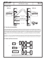
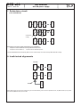
Professional Headend Solutions
Operating instructions
Bus Extender
with 8A-power supply
Content
1. Safety and operating instructions ............................................3
2. Device variants .........................................................................3
3. General .....................................................................................3
4. Front view .................................................................................4
5. Functional description ..............................................................4
7. Redundancy circuit ..................................................................5
9. Technical data ..........................................................................6
11. Document history ...................................................................7
BEB x00
Part No: 904x.0x
IMPORTANT CUSTOMER INFORMATION
Dear customer,
Please note that the maximum specified current supply of the power supply must not be exceeded,
otherwise there is a risk of irreversible corruption of the module.
Important!
Determine before startup, the current consumption for all of the modules currently connected exactly.
If the stated in the data sheet maximum current is being exceeded please reduce the current load by
redistribution or reduction of the connected modules so that the maximum current is no longer
exceeded.
With kind regards
Your Blankom team service
BEB
x00
Part N : 904x.0x
Bus Extender
with 8A-power supply
o
%
LINE
1. Safety and operating instructions
When assembling, starting-up and adjusting the modules, it is necessary to consider the system specific
references in the manual instruction!
The modules may only be installed and started up by authorized technical personnel!
When assembling the modules into the receiving points, the adherence of the EMC regulations is to be secured!
The assembly and wiring have to be done without voltage!
All active modules may only be operated with the Headend Controller HCB x00 or Bus Extender BEB x00!
The main voltage and the operating voltage of the modules working by DC have to be in complience to the operating
parameters described in the technical data.
With all work the defaults of the DIN EN 50083 have to be considered! Especially the safetyrelevant execution of the
DIN EN 60728-11 [1] is necessary!
2. Device variants
BEB 200
BEB 300
BEB 300
9047.01 Bus Extender with 8A-power supply (100 ... 240 V~ input)
9048.01 Bus Extender with 8A-power supply (48 V– input)
9048.02 Bus Extender with 8A-power supply (48 V– input)
3. General
The Bus Extender BEB x00 is a module of the head end system B-LINE but can also be used for the C-LINE/ C-LINE+ head end
system. The B-LINE is a complete system for the middle sized distribution network, while the C-LINE/ C-LINE+ is for smaller distribution networks. All active modules are programmed at the central Headend Controller (HCB x00).
The individual modules will be addressed at the address switch at the Bus Extender (line) and the respective modules (position).
The status of the individual modules will be displayed by colored LEDs:
· Red ERROR
· Green - READY
· Yellow - ADDR.
Operating voltage failure
Operating status
Remote control access or redundancy function
3
BEB
x00
Part N : 904x.0x
Bus Extender
%
with 8A-power supply
o
LINE
4. Front view
BEB 200
BEB 300
(X3)
(X2)
(X1)
8
3
ADDRESSING SPACE
INPUT VOLTAGE (DC)
INPUT POWER
ADDRESSING SPACE
OUTPUT (DC)
15 UNITS
36...72 V
max. 110 W
15 UNITS
12 V, max. 8 A
BUS EXTENDER
POWER SUPPLY
Type: BEB 200
Part No.: 9047.01
BUS EXTENDER
POWER SUPPLY
Type: BEB 300
Part No.: 9048.02
INPUT VOLTAGE (AC)
INPUT FREQUENCY
INPUT POWER
ADDRESSING SPACE
OUTPUT (DC)
INPUT VOLTAGE (DC)
INPUT POWER
ADDRESSING SPACE
OUTPUT (DC)
100 ... 240 V
50/ 60
Hz
max. 110 W
15
UNITS
12 V,
max. 8A
36 ... 72
max. 110
max. 15
12 V,
V
W
UNITS
max. 8A
Operating voltage/
control bus
LED „ERROR“ (red)
LED „READY“ (green)
LED „DATA“ (yellow)
Address selection
+
Power supply
_
DC
INPUT
48 V- / max. 3.3 A
+ -
5. Functional description
The Bus Extender BEB x00 is the necessary extension module for the head end bus system. It is equipped with 3 bus connection
sockets. The sockets X1 and X3 are equivalently occupied and are serving the vertical bus extension. The X2 socket of the BEB x00 is
responsible for power supply of signal processing units (modules) within the respective line. It also defines the address of the line and
canalizes the data transfer (see chapter 6). The total power consumption of the respective line (all connected modules within one line)
may not exceed the current limit of the BEB x00. The ADDR. switch position “0” is switching the BEB x00 into redundancy operation
status. Two BEB x00 will be switched parallely. The left/ first (ADDR.= 1...15) canalizes the data transfer, the right/ second BEB x00
(ADDR.= 0) suplies current/ power. The left/ first BEB x00 overtakes the power supply of the respective line in case of a failure (see
chapter 7)
One address is made up of two parts. The fist address-part will be allocated with the address selection switch of the BEB x00 for the
total line (01/ xx ... 15/ xx) and indicates the address of the respective line, the second part will be allocated with the address selection
switch at the connected modules (xx/ 00 .. xx/ 15) and indicates the address of the respective module within the line. (see chapter 8)
Module
ADDR. 15
Module
ADDR. 15
Module
ADDR. 15
Module
ADDR. 01
Module
ADDR. 01
BEB x00
ADDR. 01
Module
ADDR. 01
Module
signal processing
unit
BEB x00
ADDR. 02
BEB x00
Bus Extender
BEB x00
ADDR. 15
HCB x00
Headend
Controller
HCB x00
6. Head end bus structure
The number of the possible module connections (01 ... 15) to a
BEB x00 depends on the total power consumption of this line!
4
BEB
x00
Part N : 904x.0x
Bus Extender
%
with 8A-power supply
o
LINE
7. Redundancy circuit
Module
ADDR. 15
Module
ADDR. 15
Module
ADDR. 01
BEB x00
ADDR. 00
BEB x00
ADDR. 00
redundancy
supply
Module
ADDR. 01
BEB x00
ADDR. 01
BEB x00
ADDR. 01
Module
ADDR. 15
BEB x00
ADDR. 00
BEB x00
ADDR. 15
broken
Module
ADDR. 01
HCB x00
(Line redundancy)
Description of the power supply redundancy (line redundancy)
· Adjustment of the address 00 at the right Bus Extender per line
· Adjustment of the address (1 … 15) at the left Bus Extender per line
The left/ first BEB x00 will automatically take over the current supply of the line if the right Bus Extender is failing.
8. Invalid mixed alignements
not valid
Module
ADDR. 01
Module
ADDR. 15
Module
ADDR. 01
Module
ADDR. 15
Module
ADDR. 01
BEB x00
ADDR. 01
HCB x00
not valid
Mixed alignements on which the modules may be connected directly to the main-bus (HCB x00 at X1/ X2, BEB x00 at X1/ X3) and at
the line-bus (BEB x00 at X2) are not valid.
5
BEB
x00
Part N : 904x.0x
Bus Extender
%
with 8A-power supply
o
LINE
9. Technical data
Address extent
Extended address range
(Line address)
Address for redundancy
Modules address range
(Module address)
Power supply BEB 200
Main voltage
Voltage frequency
Main connector
Internal device fuse
Power consumption
Output voltage
Ripple noise ratio
Current drain
Current limit
Short circuit protection
Overvoltage protection
Protection class
Protection system
Radio noise suppression
Fuse
1 … 15
0
Polarity reversal protection
Power consumption
Voltage stability AC
Output DC voltage
Rippled noise ratio
Output current
Current limit
Short circuit protection
Overvoltage protection
Protection class
Noise emission
0 … 15
100 ... 240 V, (+10%/ - 5%)
47 … 63 Hz
built in connector
EN 60320-1/ C8
(IEC 320 C8) [3]
G5 x 20, T4A (IEC 127-2/ V)
max. 110 W
12 V
66 dB
max. 8 A**
yes (9 A typical)
yes
yes (≤ 14,5 V)*
II according DIN VDE 0860 [4]
IP 20
according DIN VDE 0871
(curve B) [5]
Immunity
Temperature range
Environmental conditions
Temperature range
Relative humidity
Mounting method
Mounting location
Physical information
Dimensions (l x w x h)
without 19“ - adapter
with 19” - adapter
Weight
BEB 200, 300 (9048.02)
BEB 300 (9048.01)
Power supply BEB 300 (9048.01)
Input voltage
48 V DC (36 ... 72 V DC)
Input current (at 48 V)
2.4 A
Power consumption
max. 125 W
Overcurrent protection
fold back
(at 110 ... 143% IOUT)
Overvoltage protection
16.8 ... 20 V
Max. current drain
8 A (-10 ... +43 ˚C)**
6 A (+55 ˚C)
Voltage stability
1500 V DC (input/ output)
Radio noise suppression
EN 55022 (CIS PR22)
Class B [6]
EN 61000-4-2,3,4,6,8 [7] /
ENV 50204 [8]
T 6.3 A/ 250 V “H“ (5x20,
internal“)
yes
max. 110 W
1500 V (input/ output)
12 V
66 dB
0.25 ... 8 A
yes
yes, hicc-up mode
yes (> 14.5 V)
IP 20
EN 55011 [9], EN 55022
(CIS PR22) Class B [6],
EN 50083-2 [2]
EN 61000-6-1 [10]/
EN 61000-6-2 [11]
-10 … +60 °C
-10 … +55 °C
≤ 80 % (not condensing)
vertical
splash-proof and
drip-proof
50 x 276 x 148 mm
50 x 301 x 148 mm
about 1,500 g
about 1,600 g
Delivery contents
1 x Power cord or connector
1 x Bus connector
2 x Terminal resistance 75 Ω
1 x Bus connector 400 mm
2 x Multipole sockets
Power supply BEB 300 (9048.02)
Input voltage
48 V DC (36 ... 72 V DC)
Input connection
Plug with screw termination,
with polarity protection
*
**
to reset device 2 minutes without voltage!
> 6 A only use bus cable “8 A“ !
10. Bibliography
[1] EN 60728-11: Cable networks for television signals, sound signals and interactive services Part 11: Safety
(IEC 60728-11:2005); German version EN 60728-11:2005
[2] EN 50083-2 : Cabled distribution systems for television and sound signals. Electromagnetic compatibility for equipment;
EN 50083-2:2001
[3] EN 60320-1: Appliance couplers for household and similar general purposes Part 1: General requirements
(IEC 60320-1:2001 + A1:2007); German version EN 60320-1:2001 + A1:2007
[4] DIN VDE 0860: Audio, video and similar electronic apparatus, Safety requirements (IEC 60065:2001, modified +
A1:2005, modified); German version EN 60065:2002 + A1:2006 + Cor.:2007 + A11:2008
[5] DIN VDE 0871: Radio noise suppression of high frequency units, Determination of limits for industrial, scientific and medical equipment, identical with CISPR 23 :1987
[6] EN 55022: Information technology equipment - Radio disturbance characteristics - Limits and methods of measurement
(IEC/CISPR 22:2005, modified + A1:2005); German version EN 55022:2006 + A1:2007
[7] EN 61000-4-2: Electromagnetic compatibility (EMC) - Testing and measurement techniques-Electrostatic discharge
immunity test, 2009-05-31
6
BEB
x00
Part N : 904x.0x
Bus Extender
%
with 8A-power supply
o
LINE
EN 61000-4-3: Electromagnetic compatibility (EMC) - Part 4-3 : Testing and measurement techniques - Radiated, radiofrequency, electromagnetic field immunity test (IEC 61000-4-3:2006 + A1:2007); German version EN 61000-4-3:2006 +
A1:2008
EN 61000-4-4: Electromagnetic compatibility (EMC) - Part 4-4: Testing and measurement techniques - Electrical fast
transient/burst immunity test (IEC 61000-4-4:2004); German version EN 61000-4-4:2004
EN 61000-4-6: Electromagnetic compatibility (EMC) - Part 4-6: Testing and measurement techniques - Immunity to conducted disturbances, induced by radio-frequency fields (IEC 61000-4-6:2003 + A1:2004 + A2:2006)
EN 61000-4-8: Electromagnetic compatibility (EMC) - Part 4-8: Testing and measurement techniques - Power frequency
magnetic field immunity test (IEC 77A/694/FDIS:2009); German version FprEN 61000-4-8:2009
[8] ENV 50204: Radiated electromagnetic field from digital radio telephones - Immunity test, 1996-02-15
11. Document history
Version
Date
Modification
Author
1.00
15.04.2009
basic document
Häußer, Rudolph
1.01
11.08.2009
revision
Häußer
1.02
11.01.2010
insert of BEB 300 (9048.01)
Häußer
1.03
19.01.2011
insert of BEB 300 (9048.02)
Häußer
1.04
24.06.2014
information sheet added
Appelfelder
1.05
14.07.2015
new company
Häußer
Options available upon request! Subjects to changes due to technical progress.
BLANKOM systems GmbH
Hermann-Petersilge-Straße 1 • 07422 Bad Blankenburg • Germany • Telefon +49 (0) 3 67 41 / 60-0 • Fax +49 (0) 3 67 41 / 60-100
7
Declaration of Conformity
Manufacturer:
BLANKOM systems GmbH
Hermann – Petersilge – Straße 1
07422 Bad Blankenburg
Germany
Product Name:
Bus Extender
Type Name:
BEB 200, BEB 300
Type No:
9047.01, 9048.01, 9048.02
BLANKOM systems GmbH confirms that the mentioned products meet the guideline(s) of the
Council for the approximation of legislation of the member states.
Electromagnetic compatibility (2004/ 108/ EC)
The following standards are met:
DIN EN 50083-2: 2007-04 (EN 50083-2:2006-06)
Low voltage guideline (2006/ 95/ EC)
The following standards are met:
DIN EN 60950-1: 2006-04 (EN 60950-1:2006-11)
Information technology equipment -Safety-
Restriction of hazardous substances (2011/ 65/ EC)
The following standards are met:
DIN EN 50581: 2013-02 (EN 50581:2012)
Bad Blankenburg, Germany, 2015-07-14
Wolfgang Schlüter
(Managing Director)
8