1
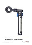
FVA Trogflux variable area flowmeter
Operating Instructions
© MECON GmbH 05/2013 OI_FVA_Trogflux_EN
Imprint
All rights reserved. It is prohibited to reproduce this document, or any parts thereof, without prior written
authorization of MECON Flow Control Systems GmbH.
Subject to change without notice.
Copyright 2013 by
MECON Flow Control Systems GmbH - Röntgenstraße 105 - 50169 Kerpen
Page 2 / 20
www.mecon.de
Operating instructions FVA Trogflux
05/2013 OI_FVA_Trogflux_EN
Contents
Contents
1 Safety Instructions ________________________________________________________ 4
1.1 Intended use .............................................................................................................. 4
1.2 Certifications .............................................................................................................. 5
1.3 Safety instructions from the manufacturer...................................................................... 5
2 Start-up _________________________________________________________________ 6
2.1 Standard device .......................................................................................................... 6
3 Installation ______________________________________________________________ 7
3.1 Installation instructions ................................................................................................ 7
3.2 Installation ................................................................................................................. 7
4 Service _________________________________________________________________ 8
4.1 Storage ...................................................................................................................... 8
4.2 Maintenance ............................................................................................................... 8
4.3 Returning the device to the manufacturer ...................................................................... 8
5 Device Description _________________________________________________________ 9
5.1 Scope of delivery ........................................................................................................ 9
5.2 Versions ..................................................................................................................... 9
5.3 Nameplate................................................................................................................ 10
6 Description Code _________________________________________________________ 11
7 Measuring range liquids ____________________________________________________ 13
8 Measuring range air _______________________________________________________ 14
9 Technical data ___________________________________________________________ 14
9.1 Pressure und temperature limits ................................................................................. 15
9.2 Dimensions .............................................................................................................. 16
9.3 Float selection........................................................................................................... 16
10 Contacts _______________________________________________________________ 17
Operating instructions FVA Trogflux
05/2013 OI_FVA_Trogflux_EN
www.mecon.de
Page 3 / 20
Safety Instructions
1 Safety Instructions
1.1 Intended use
The FVA Trogflux variable area meters are used to measure the volume of transparent liquids and
gases into closed piping. The variable area meters can also be used for flow monitoring if they are
equipped with one or more switching contacts. Standard scales are available for liquids with a
density of 1 kg/l (62.43 lb/cu.ft). The scales must be recalculated for all other media depending on
the physical characteristics.
The devices are particularly suitable for the measurement of:
•
Water
•
Clear liquids
•
Gas flows
Warning !
The operator of these measuring devices is solely responsible for the suitability,
intended use and corrosion resistance of the selected materials. It must be particularly ensured that the materials selected for the wetted parts of the flowmeter are
suitable for the process media to be measured.
The manufacturer is not liable for any damage resulting from improper or unintended
use of these devices.
No external loads may act upon the meter. The flowmeters are primarily designed for static applications.
Caution!
Hot surfaces resulting from hot process media.
Danger of burns resulting from surface temperatures above 70 °C.
● Take appropriate protective measures, for example contact protection.
● The design of the contact protection must meet the maximum permissible ambient
temperature of the meter.
The flowmeter may only be operated within the pressure and voltage limits specified on the name
plate.
Before taking the flowmeter out of operations, check that the unit is free of hazardous media and
de-pressurized.
Page 4 / 20
www.mecon.de
Operating instructions FVA Trogflux
05/2013 OI_FVA_Trogflux_EN
Safety Instructions
1.2 Certifications
CE marking
The manufacturer certifies that the device FVA Trogflux meets all statutory requirements
of the following EC directives by applying the CE marking:
•
Pressure equipment directive 97/23/EC
The most hazardous permissable media are
-
for gases: fluids of group 2
-
for liquids: fluids of group 1.
1.3 Safety instructions from the manufacturer
Disclaimer
The manufacturer will not be liable for any damage resulting from the use of its product, including,
but not limited to direct, indirect, incidental, punitive and consequential damages.
Any product purchased from the manufacturer is warranted in accordance with the relevant
product documentation and our Terms and Conditions of Sale.
The manufacturer reserves the right to revise the content of its documents, including this
disclaimer, without prior notification, and will not be liable in any way for possible consequences of
such changes.
Product liability and warranty
Mecon GmbH assumes no guarantee for repair work carried out by the customer without prior
notification and consultation. Any instruments or parts rejected by a customer must be returned to
us, if no other arrangement has been made.
General information
This manual is intended for the correct installation as well as operation and maintenance of the
devices. Read the instructions carefully before installing the device and placing it into operation.
Specially designed or customised models and specialised applications are not included in this
manual.
Operating instructions FVA Trogflux
05/2013 OI_FVA_Trogflux_EN
www.mecon.de
Page 5 / 20
Start-up
2 Start-up
2.1 Standard device
When starting up the unit, the following points must be observed:
●
Make sure that the actual operating conditions (pressure and temperature) do not exceed the
limits specified on the nameplate.
●
Avoid float impact!
Therefore it is recommended to start with a closed shut-off valve during commissioning and
adjust the operating pressure by opening the valve slowly.
In particular, the use of magnetic valves is not recommended in this case.
●
When measuring liquids, make a careful release of the pipeline to prevent pressure peaks by
gas bubbles.
●
When commissioning new devices increasingly residues can stick on the float. Therefore we
recommend to clean the equipment after a relatively short time.
●
When using the devices in the lower measuring range the device must be operated at a higher
flow rate for a short time to enable settling of the float.
Exceptions for the measurements of gases:
●
Provide valves downstream the flowmeter if pabs > 1,013 bar and usually upstream the flowmeter if pabs = 1,013 bar (no overpressure).
●
Install a flow control valve close to the flowmeter (downstream), to prevent oscillations during
the measurement.
●
Adjust the operating pressure exactly to the reference pressure (during calibration) to prevent
measurement errors.
Page 6 / 20
www.mecon.de
Operating instructions FVA Trogflux
05/2013 OI_FVA_Trogflux_EN
Installation
3 Installation
3.1 Installation instructions
Information !
All instruments are carefully checked for proper function before shipment. Check
immediately on receipt, the outer packing carefully for damage or signs of improper handling.
Report damage to the carrier and your competent sales staff. In such cases, a
description of the defect, the type and the serial number of the device is indicated.
Information !
Unpack the unit carefully to avoid damage.
Information !
Check the completeness of the delivery by using the packing list. Check the name
plate, if the delivered flow meter is according to your order. Especially check units
with electrical components for the correct supply voltage.
3.2 Installation
For specific device sizes the float is inserted with a plastic net for transport lock. This must be
removed through the top of the meter before installation. After that the free movement of the
float inside the flow tube should be checked again.
The device must be mounted vertically and stress-free. Reductions, extensions, and control
elements upstream and downstream of the meter have no influence on the measurement
accuracy with liquids. For gases, however, the installation of the meter is recommended before
valves to prevent compression oscillations.
Since variable area flow meters are very sensitive to changes in flow, control elements should
always be adjusted slowly. The calibration is carried out for defined conditions. It is essential to
ensure compliance with the calibration conditions. Deviations of the density, pressure or
temperature of gases, as well as density and viscosity of liquids, result in errors. Therefore it is
essential to specify the following data of the medium in the order: the medium, the density and
the viscosity at operating temperature and pressure. For gases, the exact reference point for
the pressure (gauge or absolute pressure) is also required.
Retrofitting of switching contacts is only possible when the floats are equipped with magnets.
When commissioning the contact we recommend to ensure the correct position of the bistable
contact by moving the float along the contact in flow direction.
Operating instructions FVA Trogflux
05/2013 OI_FVA_Trogflux_EN
www.mecon.de
Page 7 / 20
Service
4 Service
4.1 Storage
Store the device dry and dust free.
Avoid direct exposure to the sun and heat.
Avoid external loads on the device.
The admissible storage temperature for standard devices with electrical components: -40 … +70 °C.
4.2 Maintenance
The devices are built for low maintenance operations but periodically the flowmeters should be
inspected for signs of corrosion, mechanical wear as well as damage to the fitting and the display
unit.
We advice to carry out inspections at least once a year.
For a detailed inspection and cleaning the device must be removed from the piping.
Caution !
Appropriate safety precautions have to be taken when removing the device. Always
use new gaskets when reinstalling the device in the piping..
4.3 Returning the device to the manufacturer
This device has been carefully manufactured and tested.
Should you nevertheless need to return a device to MECON GmbH please observe the following
points:
Caution !
According to the actual waste disposal directives, the owner/customer is responsible
for the waste management of hazardous and toxic waste.
For reasons of environmental protection and safeguarding the health and safety of
our personnel all devices sent to MECON GmbH to be repaired must be free
of toxic and hazardous substances. This also applies to cavities of the
devices. If necessary the customer is kindly requested to neutralize or
rinse the devices before returning them to MECON.
The customer has to confirm this by filling in an appropriate form which is available
for download on the MECON website:
www.mecon.de/en/declaration/contamination.pdf
Caution !
In case of returning devices which contain hazardous and toxic substances MECON
GmbH is entitled to dispose of these substances at cost to the customer without any
further notices
Page 8 / 20
www.mecon.de
Operating instructions FVA Trogflux
05/2013 OI_FVA_Trogflux_EN
Device Description
5 Device Description
5.1 Scope of delivery
1 flowmeter FVA Trogflux
2 Operating instructions
3 Certificates (optional)
Fig. 1
Scope of delivery
Information !
Please check the delivery for completeness using the packing list.
5.2 Versions
Fig. 2
Standard device with
PVC adhesive bushing
Fig. 3
Standard device with
female thread
The main components of the FVA Trogflux are the measuring tube made of plastics, the float and
the connecting parts. A scale is printed on the flow tube (eg in l / h). The actual flowrate is read at
Operating instructions FVA Trogflux
05/2013 OI_FVA_Trogflux_EN
www.mecon.de
Page 9 / 20
Device Description
the position of the largest diameter of the float. For process monitoring and control, the unit can be
equipped with one or more contacts.
Special features
•
Product scales for liquids and gases
•
Easy to install
•
Low cost plastic version
•
Short delivery times for standard versions
5.3 Nameplate
Important !
Please refer to the device nameplate to ensure that the device is built
according to your order.
Check particularly for the correct supply voltage.
Fig. 4
Nameplate of the FVA Trogflux
Code number
Device specific code number
TS Medium
Maximum temperature of the medium
PS
Maximum pressure of the medium
Pmax at Tmax
Maximum pressure of the medium at temperature Tmax
Page 10 / 20
www.mecon.de
Operating instructions FVA Trogflux
05/2013 OI_FVA_Trogflux_EN
Description Code
6
Description Code
The descripion code consists of the following elements:
1
Plastic material for measuring cone
1
Trogamid
2
Polysulfon
2
Gasket material
1
Perbunan
4
Viton
8
EPDM
3
Measuring cone size
AC
125
BC
315
CD
650
DD
1000
EDx
1600
FD
2500
GE
4000
HE
6500
JE
10000
KE
16000
LE
20000
ME
25000
4
1
Float material
Stainless steel (Mat.-No. 1.4305)
2
Stainless steel (Mat.-No. 1.4571/1.4404)
3
PVC, weighted
4
Stainless steel Mat.-No. 1.4571/SV/316Ti
5
Aluminium
6
PVC, not weighted
7
PVDF, not weighted
8
PVDF, weighted
Operating instructions FVA Trogflux
05/2013 OI_FVA_Trogflux_EN
www.mecon.de
Page 11 / 20
Description Code
5
1
Connection material
PVC / Standard, for plastic tubes only
2
Cast iron (only for G½, G1 , G2)
3
Steel (not for G½, G1, G2)
4
Stainless steel
6
1
Connection form
Adhesive bushing (only made of PVC)
2
Female thread DIN ISO 228
3
Female thread NPT (NPT ANSI B1.20.1)
7
Connection size
A
Adhesive bushing
B
Female thread G¼
C
Female thread G⅜
D
Female thread G½
E
Female thread G¾
F
Female thread G1
G
Female thread G1 ¼
H
Female thread G1 ½
J
Female thread G2
8
Contacts (only with magnetic floats)
A
Without contact
C
Contact K18/A (closes on falling below the limit)
D
Contact K18/B (closes on exceeding the limit)
E
2 Contacts K18/A
F
2 Contacts K18/B
G
One of each contact K18/A and K18/B
9
0
Float version
Standard
1
With magnet
2
Guided
10
Other versions
B06
With calbration certificate
Y01
Measured medium: always required, specify in plain text (Medium, Measuring range,
Device range; Density; Viscosity, Operating temperature, Operating pressure)
Y04
Silicone-free version
Y99
Special version: specify in plain text
Page 12 / 20
www.mecon.de
Operating instructions FVA Trogflux
05/2013 OI_FVA_Trogflux_EN
Measuring ranges for liquids
7 Measuring ranges for liquids
Standard Measuring range for liquids (ρ
ρ=1 kg/l, Viscosity 1mPa⋅⋅s)
Connection
Measuring
cone
Dynamic
Maximum measuring range for the selected floats
PVC
Female
Adhesive thread
bushing
[mm]
20
(G¼),
Stainless steel
Pressure
loss float
PVC/PVDF
PVC/PVDF
Stainless
steel
Stainless
steel
with
magnet
weighted
with magnet
weighted
viscosity
l/h
l/h
l/h
l/h
l/h
mbar
C125
1:10
125
120
65
65
100*
11
G½
C315
1:10
315
300
175
175
240*
13
(G½),
D6501)
1:10
TS 650
TS 600
TS 500
TS 450
TS 400*
17
D6502)
1:10
PS 600
PS 550
PS450
PS 400
PS 350*
17
D1000
1:10
1000
950
750
700
600*
17
D1600
1:10
1600
1500
1250
1100
1000*
20
D2500
1:10
2500
2400
2000
1750
1400*
24
E4000
1:10
4000*
3800*
3200
3200
2500*
25
E6500
1:10
6500*
6400*
5000
5000
4000*
27
F10000
1:10
10000*
9500*
7500
7500
5500*
32
G16000
1:4
16000*
16000*
12500
12500
-
51
H20000
1:3
20000*
19000*
-
-
-
65
J25000
1:3
25000*
24000*
-
-
-
91
(G⅜),
32
(G¾),
G1
63
(G1 ¼),
(G1 ½),
G2
(Connections in brackets are not standard)
1)
Measuring cone made of Trogamid
2)
Measuring cone made of Polysulfon
Operating instructions FVA Trogflux
05/2013 OI_FVA_Trogflux_EN
www.mecon.de
*)
guided float
Page 13 / 20
Measuring ranges for air
8 Measuring ranges for air
Standard Measuring range for air (pabs = 1,013 bar, at T=0 °C, ρ=1,293 kg/m³, viscosity 0,0181 mPa⋅⋅s)
Connection
Measuring
cone
Dynamic
Maximum measuring range for the selected floats
Aluminium
PVC
adhesive
bushing
[mm]
Female
threads
20
(G¼),
Pressure loss
float
PVC/PVDF
with magnet not weighted
Aluminium
weighted
l/h
l/h
l/h
l/h
mbar
C125
1:10
2000
2500
1400
2200
4
C315
1:10
5000
6400
3400
6000
5
D6501)
1:10
TS 10000
TS 12000
TS 7000
TS 10000
7
D6502)
1:10
PS9000
PS10500
PS 6500
PS 9000
7
D1000
1:10
16000
20000
11000
16000
7
D1600
1:10
28000
32000
18000
25000
7
D2500
1:10
40000
50000
28000
40000
8
E4000
1:10
64000*
75000*
45000
60000
9
E6500
1:10
100000*
125000*
75000
100000
10
F10000
1:10
160000*
180000*
120000
160000
13
G16000
1:4
280000*
300000*
190000*
-
23
H20000
1:3
350000*
400000*
240000*
-
31
J25000
1:3
430000*
480000*
300000*
-
43
(G⅜),
G½
32
(G½),
(G¾),
G1
63
(G1 ¼),
(G1 ½),
G2
(connections in brackets are not standard))
1)
Measuring cone made of Trogamid
2)
Measuring cone made of Polysulfon
Page 14 / 20
www.mecon.de
*
guided float
Operating instructions FVA Trogflux
05/2013 OI_FVA_Trogflux_EN
Technical Data
9 Technical Data
Input
Flow
from the bottom to top upwards
Pressure limit
max. 10 bar
Application conditions
Environmental conditions (temperature limits)
Measuring cone made of Trogamid
max. 60 °C (for water 50 °C)
Measuring cone made of Polysulfon
max. 80 °C
Pressure- & temperature limits
see table at chapter 9.1 (page 15)
Measuring accuracy
For liquids
G 2,5 qG 50% (acc. VDE/VDI 3513, sheet 2)
For air
G 2,5 qG 50% (acc. VDE/VDI 3513, sheet 2)
Measuring range
For liquids
12,5 l/h … 25 m³/h
For gases
200 l/h … 430 m³/h
Measuring units
Measuring cone D2500 and smaller
l/h
Measuring cone E4000 and larger
m³/h
Construction design
Measuring tube material
PVC-adhesive bushing, female thread, cast iron
Measuring cone material
Trogamid, Polysulfon
Connection (union nut)
PVC, cast iron
Connenction (inlay part)
PVC, cast iron, steel, stainless steel
Float
Stainless steel, Aluminium, PVC, PVDF
Float guide rod
Stainless steel
(optionally for measuring cone C125 to D2500)
Gasket
NBR (NB2), FKM, EPDM
Stopper
Polysulfon
9.1 Pressure and temperature limits
T[°C]
-10 bis +60*
*
80
for water only up to +50°C
Trogamid
Polysulfon
Pe [bar]
10,0
Pe [bar]
10,0
-
10,0
Connection parts PVC DIN 8062
Medium
For water and nonaggressive liquids
For aggressive media
T [°C]
20
40
60
20
40
60
Pe [bar]
10,0
10,0
2,5
10,0
4,0
1,0
Pe = eff. pressure = overpressure
Operating instructions FVA Trogflux
05/2013 OI_FVA_Trogflux_EN
www.mecon.de
Page 15 / 20
Technical Data
9.2 Dimensions
Fig. 5
Trogflux, Dimensions in mm
Connection
Dimension A
[mm]
Female thread
Cast iron
PVC/PVDF/
stainless steel
Dimension B
[mm]
Weight
[kg]
Adhesive
bushing
Adhesive
bushing
[mm]
Female thread
Adhesive
bushing
20
G½; NPT ½"
346 ± 4
350 ± 4
366 ± 4
306
0,4
32
G1; NPT 1"
356 ± 4
358 ± 4
358 ± 4
306
0,7
63
G2; NPT 2"
389 ± 4
379 ± 4
366 ± 4
306
2,2
9.3 Float selection
There are three versions of floats available:
(reading edge)
•
Float non guided (A)
•
Float guided (B)
•
Float for stable viscosity (C)
Fig. 6
Page 16 / 20
www.mecon.de
Versions of float
Operating instructions FVA Trogflux
05/2013 OI_FVA_Trogflux_EN
Contacts
10 Contacts
The bistable contact K18 is intended for signaling of limit values and for controlling purposes.
Special features
•
bistable function
•
high vibration resistance
•
no interaction between contacts
•
low cost plastic version
•
easy to use elelctrical connection
Mode of operation
A bistable reed contact consists of a spring contact which is covered by a glass tube filled with inert
gas. It is operated by a magnetic field. This magnetic field is generated by a permanent magnet
inside the float of a MECON flowmeter.
There are two versions availabe:
Fig. 7 Contact K 18 A
Fig. 8 Contact K 18 B
K 18 A: contact closes on falling below the limit
K 18 B: contact closes on exceeding the limit
Electrical loadability
The spring contacts of the K18 are sensitive to current overload (max. 500 mA). A high current
could lead to a welding effect and this will damage the contact blades – this specifically applies to
inductive loads e.g. relais (high self-induction).
Protective circuits
At great cable lengths (cable capacity) it is recomended to connect a protectice resitor in series to
contact K18 A(B) for current limitation.
Fig. 9 Protective circuit for current limitation
Operating instructions FVA Trogflux
05/2013 OI_FVA_Trogflux_EN
www.mecon.de
Page 17 / 20
Contacts
When using a DC power supply in combination with an inductive load it is recomended to connect a
diode in parallel to the load.
Fig. 10 Protective circuit for inductive loads and DC power supply
Technical data
Contact material
Rhodium (with inert gas)
max. switching capacity
5 W / 10 VA
Max. switching voltage
250 V DC/AC
Contact resistance
0,1 Ω
Isolation resistance
1011 Ω
Contact closing time
2 ms
Contact opening time
0,07 ms
Frequency of operation
2000 Hz
Duration of bounce
0,5 ms
Temperature range
-40 °C to +80 °C
Material of housing
Plastics
Electrical connection
Rectangular connector acc. to DIN EN 175301-803
(previously DIN 43 650)
Protection class
IP 65
Max. starting current (peek)
0,5 A
Max. switching current
230 V DC
: 21 mA
115 V DC
: 43 mA
24 V DC
: 0,2 A
10 V DC
: 0,5 A
Warning !
Observe in any case the max. switching capacity and the max. starting current –
otherwise a welding effect will damage the contact blades.
Page 18 / 20
www.mecon.de
Operating instructions FVA Trogflux
05/2013 OI_FVA_Trogflux_EN
Contacts
Installation of the connection cable to the connector:
1.
2.
3.
4.
5.
Fig. 11
Remove the cable gland (9) and take out the
gasket kit (8, 7, 6).
Remove the locking screw (5) and pull of the
housing (4) from the insert connector (3).
Insert the connection cable through the cable
gland (9), the gasket kit (6, 7, 8) and the
housing.
Connect the wires to terminal 1 and 2 of the
insert connector.
Assamble the rectangular connector in reverse
order as described above. Please note, that
the cable outlet can be varied by rotating the
insert connector (4) through 90°.
Explosion drawing contact K 18
Commissioning:
When commissioning the contact K18 we recommend to ensure the correct position of the bistable
contact by moving the float along the K18 in flow direction.
Operating instructions FVA Trogflux
05/2013 OI_FVA_Trogflux_EN
www.mecon.de
Page 19 / 20
Mecon GmbH
Röntgenstraße 105
D 50169 Kerpen
Phone: +49 (0)2237 600 06 – 0
Fax:
+49 (0)2237 600 06 – 20
Email: [email protected]
www.mecon.de
OI_FVA_Trogflux
Subject to change without notice
Copyright ©