1
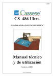
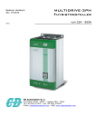
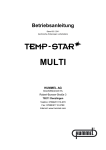
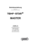
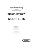
Operating instructions Z 1264/1/. . . Control unit GB 05/14 Z 6 / HK Table of contents 1. Introduction 3 2. Special features 3 3. Technical data 3 4. 4.1 Electrical connection Pin diagram for Z 1264 /1/. . . 4 4 5. 5.1 Start-up Functions of the keys and displays 5 5 6. Function description of the displays with keys 6 7. Start-up control insert 8 8. 8.1 8.2 8.3 Programming Programming start Programming diagram Menu points 9 9 9 10 9. 9.1 Terminals assignment Load circuit fuses 11 11 Safety precautions 12 10. 2 1. Introduction The HASCO control units Z 1264 /1/. . . are easy to operate with their use of front switches. 2. Special features Z 1264/. . . 쐽 Programmable soft start. 쐽 Clear alarm diagnosis. 쐽 Manual or automatic change to selector mode. 쐽 1 to 24 control circuits using plug-in unit design.( Größere Geräte auf Anfrage ) 쐽 Modular design with 3600 watts per control circuit. 쐽 Alarm input and output as standard. The Control unit Z 1264/ 1/. . . corresponds to the important protection requirements in agreement with the EU guidelines. 3. Technical data Z 1264/1/2/... Z 1264/1/3/... Z 1264/1/5/... Z 1264/1/7/... Z 1264/1/ 9/... Z 1264/1/11/... Z 1264/1/17/... Z 1264/1/4/... Z 1264/1/6/... Z 1264/1/8/... Z 1264/1/10/... Z 1264/1/16/... Z 1264/1/24/... Outside dimensions (B x H x T) Electronic fuse /cabinet Connected voltage 175 x 200 x 390 16 A/ Phase 350 x 200 x 390 350 x 200 x 390 550 x 200 x 390 550 x 200 x 390 460 x 330 x 390 460 x 460 x 390 32 A / Phase 400 V 3 N 쓒 ± 10 % ; 50/60 Hz Power output Contactless semiconductor end step max. 16 A, in zero voltage switching 1) Thermocouple Fe-CuNi, Typ J Operating range 50 … 500°C Control accuracy ± 1°C (at optimum conditions) Ambient temperature Alarm output Power fuse Degree of protection 1) 10 … 40°C, warehouse 0 ...50°C 1 relay make contact max. 50 V 쓓, 0,5 A FF 16 / 500 IP 20 (EN 60529) = The maximum power consumption of 11KW ( 16A ) / 22KW ( 32A ) must not be exceeded ! 3 4. Electrical connection The power and thermal sensor connections between tools and the control unit Z 1264 / . . . are made with the power/signal cable Z 1225 /. . . The following must be adhered to when using all Z 1264 /1/ 9 to Z 1264 /1/ 24 control inserts : The maximum power input of 21,600 watt must not be exceeded ! 4.1 Pin diagram for Z 1264 /1/. . . (Exemples) Z 1264 / 1 / 2 / 16 230 V TC Z 1264 / 1 / 4 / 16 230 V TC Z 1264 / 1 / 6 / 16 230 V TC Z 1264 / 1 / 9 / 16 Inserts 1– 6 230 V TC Inserts 7– 9 230 V TC Allocation of pin connection according to DIN 16765 4 5. Start-up The hot runner control units are designed for connection to a three-phase electricity grid (see Technical Data). For this purpose, the unit is provided with a CEE plug. The master switch is located on the back and separates the unit completely from the power current. After careful testing of the cabling, the tool is connected to the control unit. If required, a connection to the injection moulding machine can be made via the alarm plug. The individual control inserts are switched On or Off with the I/O key. Zones that are not needed must be switched off! Set the set point temperature at the control inserts (see Displays, operation). The control inserts now heat the tool evenly, moist heating elements are dried out. When this occurs, the temperature deviation alarm displays blinks. (Softstartrampe). After reaching the set temperature, production can start with the factory settings. If malfunctions occur during start-up, then the cause of the malfunction can be recognized by the corresponding displays at the control insert (see keys and displays). 5.1 Function of the keys and displays Control insert Micro processor subassembly with power unit 16 A cordlessly plugged Alarm display Heating pulse display A indicates power output Actual value display Power display (ampere or per cent) Operating keys Set point display A % A I/O % ESC Set point input PRG 5 6. Function description of the displays and keys of Z1264/. . . Actual value display Actual temperature in °C. Display heating impulse (decimal point). Set point display (see Set point input) Display Display Display Display Display Output in amperes or % (see transfer key – output display). Actuator operation "Hnd" and output in % (see transfer key – actuator operation). Boost "tUP" (see transfer key – boost ↑). Temperature fall "tdn" (see transfer key – temperature fall ↓). "Alarm" on automatic takeover of output (see Programming) Switch-on key I/O ESC After operation (ca. 2 sec.), the control insert is switched On or Off. The module writes its current operating conditions (ON or OFF) into an internal memory. Precondition: The controller must be operated at the net min. 2 minutes after switching (ON or OFF). Insert controllers that are not used must be switched Off ! * ESC key (see programming). Set point settings Set point lower or higher (50 to max. 500 °C; see also set point limiting). Setting of the output in % in actuator operation. Up, down in programming mode (see Programming). Transfer key - output display A With this key, you can switch over the output display between amperes or % starting output. The respective symbol lights up green in front of the set point display. % Without a green LED, the set point is again displayed. Transfer key - actuator operation This key is used to activate actuator operation. The starting output is manually set in % at the set point entry (see Set point entry). In this type of operation, the actual value display changes continuously between ”Hnd” and starting output. Transfer key - BOOST With this key, the set point is temporarily increased. The set point display alternates between ""tUP" and BOOST temperature (see also Programming). 6 Transfer key - temperature fall This key is used to lower the set temperature, the fall value can be programmed from 10 to 200°C (see programming). In this type of operation the actual value display alternates constantly between ”tdn” and set point temperature. This can also be activated with the alarm plug from the machine (see terminals assignment on page 13). Alarm display - thermal sensor Is continuously lit if there is a sensor fracture; in the actual value display there is shown ”- - -”. If the automatic actuator function is active, the display alternates constantly between starting output and „not“. For reverse voltage, the display blinks for some minutes after switching on the control insert or the unit Z 1264 / 1/ . . . . The actual value display also shows ”- - -”. Alarm display - temperature deviation The soft start ramp blinks during the heating phase. Lights up continuously when rising above or falling below the set limiting temperatures (see programming). For excess temperature, the current supply is also interrupted (max set point overstepping). Alarm display - current overload / heating circuit interrupted Lights up when the set maximum current is exceeded and on interruption of the load circuit. The power supply is interrupted. 7 7. Start-up of control insert Switch main device switch On I/O Switch On control insert Z 1265/ . . . with key (ca. 2 sec.). ESC Set point settings The set point is increased or decreased by the corresponding decimal points by operating the Up and Down keys. Start switching After switching on the controller, the temperature increases to the end temperature of ramp 1 (rE = 120°C). After reaching of , the dwell time is activated (2 minutes). This permits any residual moisture in the heating elements to escape. Ramp 2 The 2nd ramp starts once the dwell time The temperature then increases to the set value. has expired for all control inserts. Set point temperature 8 8. Programming 8.1 Programming start Pressing the PRG key for longer than 2 seconds activates the programming function. If the input lock is active, "Cod" appears as the first item on the menu. The correct entry code must be entered. If the code is wrong, it will not be possible to change any parameters. The set point setting flashes in the set point window. Pressing the key again stops the flashing, and the set point can now be changed using the up and down keys. By pressing the PRG key, the new value is taken over and flashes again in the set point display. The various menu items are selected with the up and down keys (see Programming). You can quit the programming mode with the ESC key. If the settings are changed, the control insert must remain switched on for a few minutes, because only then are the changed values permanently saved! 8.2 Programming diagram START (normal operation) Menu points (Actual value display) Select menu I/O ESC setting changed no change in setting I/O I/O ESC ESC Settings Change values 9 8.3 Menu points Menu points Display at works Settings Value range Remarks Over temperature switch point 10 °C 0 … 50 °C above set value Under temperature switch point 10 °C 0 … 50 °C below set value Over current switch point 16 A 1 …16 A Temperature fall 50 °C 10 …200 °C End temperature Ramp 1 120 °C 80 …120 °C Temperature rise Ramp 1 1°C / 4 s 1°C /10 s …1°C / 2 s Temperature rise Ramp 2 1°C / 2 s 1°C /10 s …1°C / 2 s 2 min. 1 …10 min. Over temperature alarm I I = Alarm relay switches O = inactive Alarm message Low temperature alarm I I = Alarm relay switches O = inactive Alarm message Automatic actuator operation O I = active O = inactive Address input for Central module ( Z1266 ) 99 0 ... 99 Activation Manual actuator operation O I = aktiv O = inaktiv device- 1 … 99 Dwell time for end temperature Ramp 1 Zone adress only centr. control dependent (Operating time min. 15 minutes !). For active function, after sensor fracture, heating is continued with the average output performance of the past 15 minutes. Number of control circuits to be addressed 450 °C 50 … 600 °C 20°C 5 … 60 °C Temperature display selector (°C or °F) °C °C/°F Boost time 20 s 0 ... 180 s Duration of boost process Thermocouple J J/L Thermocouple selection Preset - - Set point limits Boost When switching from °C to °F, the temperature settings from the factory (°C) must be switched to °F. Reset factory settings Access code 0 (deactivated) 10 0 …250 Input lock General code 230 9. Terminals assignment Synchronization connection SUB-D 15 pole. Synchronization GND EXT Several control units can be linked together by means of the synchronization connection. This connection ensures that all units start together with ramp 2. The pins of the several units must be linked in a parallel manner. Temperature fall Control unit alarm Alarm output of the injection molding machine Alarm output of the control unit (potential-free make-break contact) Connection from the injection molding machine to the control unit Connection from the injection molding machine to the control unit _ max. 0,5 A / 50V ~ 1 9 10 2 Output 3 11 4 Input Control unit Machine 12 5 13 6 K1 14 7 15 8 9.1 Load circuit fuses The load circuit fuses are positioned on the back of the unit. Before replacing them, pull out the mains plug. Ensure that the new fuses are of the same type as the existing ones ! Zone 5 Sicherung 16A FF Zone 4 Sicherung 16A FF Zone 3 Sicherung 16A FF Zone 2 Sicherung 16A FF Zone 1 Sicherung 16A FF 11 10. Safety precautions 쐽 Z 1225 /. . . connecting cables and Z 1227/. . . connecting housings are to be used for the electrical connections (power and thermocouple connections) between control unit and the tool. This will ensure optimum controlling accuracy. 쐽 The control units are matched to the HASCO range of standard elements. No guarantee can be given for trouble-free functioning if components from other companies are used. 쐽 Connection, repair and maintenance work may only be carried out by trained electrical technicians. 쐽 During work on the control units and the linked cables, devices, machines and tools, all parts must be disconnected from the mains. The system must also be safeguarded from being unintentionally turned on again. 쐽 The Z 1225 /. . . power/signal cables must be regularly checked for mechanical damage and replaced as necessary. 쐽 The devices must be located such that sufficient ventilation and cooling is available. 쐽 The controllers must be protected from moisture and wet. 쐽 The devices must be applied in a technically meaningful way. 쐽 Unplug the unit when changing the fuse. Subject to technical modifications. Please always check all the data against the product information we publish in the internet. 쐽 If a module space is not occupied, it must be covered by a cover plate. © by HASCO · Postfach 1720 · D-58467 Lüdenscheid · Tel. +49 (0) 2351 957-0 · Fax +49 (0) 2351 957-237 · www.hasco.com · [email protected] 05 14 4 0,25 14