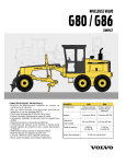
1
Gewerbegebiet 1
D-98743 Spechtsbrunn
Tel.: ++49-(0)36703-898-0
Fax.: ++49-(0)36703-898-20
Mail:[email protected]
www.apis-maschinenbau.de
Page 1
Operating Instructions for Cutting Unit
Operating Instructions for "Lost Head" Cutting Unit
with Leak Detector AP-WHS-01
Dear Customer,
We thank you for your confidence in our product.
Please read these operating instructions before using the appliance to facilitate start-up and
operation of the unit.
If you have any questions, our APIS Team is available at any time.
Our address is:
APIS Maschinenbau GmbH
Gewerbegebiet 1
D-98743 Spechtsbrunn
Tel:
++49 36703 / 898-0
Fax.:
++49 36703 / 898-20
Email:
[email protected]
Technical Data
Mach. Type:
Mach. No.:
Year of production:
Compressed air connection:
Electrical power connection:
AP-WHS-01
2 – 8 bars
230V AC / 16A
Table of Contents
1.
2.
3.
4.
Functional Description
Start-up
Care and Maintenance
Safety Precautions
Page 1/5
Gewerbegebiet 1
D-98743 Spechtsbrunn
Tel.: ++49-(0)36703-898-0
Fax.: ++49-(0)36703-898-20
Mail:[email protected]
www.apis-maschinenbau.de
Page 2
Operating Instructions for Cutting Unit
1. Functional Description
The AP-LF-01/V unit serves for cutting off lost heads and subsequent leakage test.
The items are transferred from the conveyer belt to the feed belt for cutting and then transported on
to the cutting unit.
Guided by the lateral guide the specially shaped lost head engages in the guide channel and the
drive belt for the cutting device.
The bottle rises slightly from the conveyer belt and rotates along the heated cutting blade where it is
cut.
After cutting off, the head is fed to the waste bin.
The bottle falls back onto the belt and is transferred to the leak testing belt in an upright position.
Page 2/5
Gewerbegebiet 1
D-98743 Spechtsbrunn
Tel.: ++49-(0)36703-898-0
Fax.: ++49-(0)36703-898-20
Mail:[email protected]
www.apis-maschinenbau.de
Page 3
Operating Instructions for Cutting Unit
2. Start-up
2.1 Mechanical Stage
Position the unit on the feed belt and adjust the height with the infinite hydraulic adjustment.
Complete the power connection.
2.1.1. Take an item to be processed and place
it on the cutting belt. Loosen the
mount on the lateral guide and slide it
against the item so that a gap of
approx. 1-2mm remains on each side.
Ensure that the item is not blocked at
any point by the lateral guide (please
observe diagonals on rectangular
bottles). As a rule the height of the
lateral guide should be adjusted so that
the railing is positioned in the middle
of the item.
2.1.2. Adjust the cutting device to the height
of the item with the aid of the spindle
adjustment. Adjust the cutting guide to
the diameter of the lost head and ensure that the item is hanging perpendicular in the
machine.
For this purpose loosen the clamping screws
on each of the clamping blocks and correct the
position with the appropriate spindle. After
correcting the adjustment please retighten the
clamping screws.
The guide and drive belt can be adjusted with
the spindle adjustment!
Adjust blade to cutting edge with the M8
clamping screws on blade block and
appropriate intermediate position with feeler
gauge (0.8±0.2mm) between blade mount and
groove guide.
Page 3/5
Gewerbegebiet 1
D-98743 Spechtsbrunn
Tel.: ++49-(0)36703-898-0
Fax.: ++49-(0)36703-898-20
Mail:[email protected]
www.apis-maschinenbau.de
Page 4
Operating Instructions for Cutting Unit
2.1.3. Now adjust the plug to the cut item to be tested. Position the item below the plug.
Adjust the height of the plug units so that the bottom of the sealing plate is approx.
10-30 mm above the neck of the bottle when the plug cylinder is retracted.
After adjusting the height, adjust the plug so that it is centered above the opening in
the item.
2.1.4. Now adjust the light barrier for positioning the item in the test position. "Light
barrier“ 4B2 is responsible for positioning the item in the test position. The light
barrier must be positioned so that the feed belt stops when the item is centered below
the plug cylinder.
2.1.5. "Light barrier" 4B3 should be offset by the width of the bottle, to give the reject
signal for leaky items. Adjust the eject nozzle to the same interval in the lower third
of the bottle.
2.1.6. "Light barrier“ 5B2 is responsible for recognition of items in a prone position. This
is located below the eject cylinder. (Optional)
2.1.7. It is necessary to take the belt speed into consideration for all adjustments. Allow the
cutting belt to run slightly faster than the feed belt, so that the bottles arrive at the
cutting station with a slight interval in between. This, on the other hand, must be
matched to the speed on the cutting belt. Adjust the speeds using the frequency
converters in the left switch cabinet.
2.1.8. The blade can be heated for easier, fuzz-free cutting. The heater can be switched on
and off separately on the switch cabinet. Set the temperature of the blade on the
heater control using the arrow keys.
2.1.9. The speed of the belt on the leak detector can be set with the keypad on the display.
Follow the instructions for the leak detector.
Page 4/5
Gewerbegebiet 1
D-98743 Spechtsbrunn
Tel.: ++49-(0)36703-898-0
Fax.: ++49-(0)36703-898-20
Mail:[email protected]
www.apis-maschinenbau.de
Page 5
Operating Instructions for Cutting Unit
2.2 Operation
Switch on the unit with the main switch. Switch on the drives for the cutting device and the blade
heater on the left switch cabinet.
The feed belt is equipped with a vacuum device to prevent the bottles from tipping over on the feed
belt. Switch on the vacuum pump, if required.
Switch the leak detector on and off with key "K1 Start/Stop“ on the control panel.
The leak test can be switched on and off with key "K2 Leak test ON/OFF".
If "Leak test OFF" is selected, only the conveyer belt runs. (pass-through mode)
It is only possible to change the function "Leak test ON/OFF“ with key "K2 Leak test
ON/OFF"
when the system is stopped ("K1 Stop“).
The reference leak can be switched on and off with key "K3 Reference leak ON/OFF".
Messages can be displayed directly by pressing key "K4 Messages".
Further details on using the leak detector are given in the operating instructions for the leak
detector.
3. Care and Maintenance
♦ The condensate should be drained at the maintenance unit on the side of the switch cabinet
regularly depending on the quantity of condensate in the compressed air network, however at
least once a month.
♦ The filter in the maintenance unit should be checked for clogging once a month.
4. Safety Precautions
•
•
•
•
•
•
•
•
•
•
Hazard from moving machine parts
Danger of being pulled into running conveyer belt
Do not wear bracelets. Wear tight-fitting clothing
Danger of being cut on blade
Danger of being burned on blade and blade arm
Never reach into the operating and testing are when the machine is switched on
Always ensure that the machine is switched off and secured before performing any type of
maintenance or repair work
Danger from components under pneumatic pressure
Leakage or detaching air hoses
Perform maintenance and repair work only with compressed air line closed
Page 5/5