1
Operating Instructions
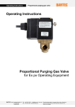
Digital Purging Gas Valve
Operating Instructions
Digital Purging Gas Valve
for Ex px operating equipment
BARTEC
GmbH
Max-Eyth-Straße 16
D-97980 Bad
Mergentheim
Tel.: +49 7931 597-0
Fax: +49 7931 597119
[email protected]
www.bartec.de
Reservation
Technical data subject to change without notice. Alterations,
errors and misprints may not be used as a basis for any
claims for damages.
Operating Instructions
Digital Purging Gas Valve
Table of Contents
1.
SAFETY ...........................................................................................................................3
1.1
1.2
1.3
1.4
1.5
1.6
1.7
1.8
2.
PRODUCT DESCRIPTION ..............................................................................................9
2.1
2.2
2.3
2.4
2.5
3.
Function..............................................................................................................................9
Picture of the product .........................................................................................................9
Variants ............................................................................................................................10
Selection table for purging air nozzle ...............................................................................10
Construction of the digital purging gas valve....................................................................11
MOUNTING....................................................................................................................12
3.1
3.2
4.
This manual........................................................................................................................3
Handling the product ..........................................................................................................4
Use in accordance with the intended purpose ...................................................................4
1.3.1
Exclusive purpose..............................................................................................4
1.3.2
Improper use......................................................................................................4
Operator’s obligations ........................................................................................................4
Safety Instructions..............................................................................................................5
1.5.1
Electrical system ................................................................................................5
1.5.2
Installation..........................................................................................................5
1.5.3
Operation ...........................................................................................................5
1.5.4
Maintenance ......................................................................................................6
1.5.5
Assembly/disassembly.......................................................................................6
1.5.6
Repairs...............................................................................................................6
Standards conformed to .....................................................................................................7
Ex protection type marking and certification.......................................................................7
Warranty.............................................................................................................................8
Mounting...........................................................................................................................12
Electrical connection ........................................................................................................13
COMMISSIONING .........................................................................................................14
4.1
4.2
4.3
Inspections before commissioning ...................................................................................14
Adjusting the leakage loss rate ........................................................................................14
Commissioning.................................................................................................................14
5.
OPERATION ..................................................................................................................15
6.
MAINTENANCE AND CARE .........................................................................................15
7.
MALFUNCTIONING AND TROUBLESHOOTING.........................................................16
8.
TECHNICAL DATA........................................................................................................17
9.
DIMENSIONS.................................................................................................................18
10.
RATE OF AIR LEAKAGE ..............................................................................................18
11.
DECLARATION OF EC CONFORMITY ........................................................................19
Technical data subject to change without notice.
Digital purging gas valve 05_0056_7D0001/Issue A. 01
Page 2 of 22
Operating Instructions
1.
Safety
1.1
This manual
Digital Purging Gas Valve
This manual contains the information required for using the digital purging gas valve in accordance with its intended purpose. It is addressed to
technically qualified personnel.
Familiarity with and the technically perfect implementation of the safety
instructions and warnings described in this manual are preconditions for
safe installation and commissioning. The safety notes and warnings in
this documentation are given in a general way and only qualified personnel will have the necessary specialised know-how to interpret and
implement them correctly in specific individual cases.
This manual is an integral part of the scope of supply even if for logistical
reasons it can be ordered and delivered separately. If you need any further information, please ask the BARTEC branch that is near you or responsible for your area.
It is essential to read and observe the contents of this documentation
and this chapter in particular before you install and operate the digital
purging gas valve.
Keep this manual and other documentation relating to the Ex pz operating equipment close to hand at all times.
Particularly important points in this documentation are marked with a
warning symbol:
DANGER
Non-observance leads to death or serious physical injury. The necessary safety measures must be taken.
CAUTION
Warning of damage to property and financial and penal disadvantages
(e.g. loss of guarantee rights, liability etc.).
ATTENTION
Important instructions and information on preventing disadvantageous
behaviour.
NOTE
Important instructions and information on effective, economical and
environmentally compatible handling.
Technical data subject to change without notice.
Digital purging gas valve 05_0056_7D0001/Issue A. 01
Page 3 of 22
Operating Instructions
1.2
Digital Purging Gas Valve
Handling the product
The product described in this manual was tested and left the factory in
perfect condition as regards meeting safety requirements. To maintain
this state and ensure that this product operates perfectly and safely, it
may be used only in the manner described by the manufacturer. Appropriate transportation, suitable storage, and careful operation are also essential for the perfect and safe operation of this product.
The digital purging gas valve must be mounted properly and securely on
the Ex p operating equipment if it is to work perfectly and correctly.
1.3
Use in accordance with the intended purpose
1.3.1
Exclusive purpose
The digital purging gas valve serves exclusively as a 2/2-way solenoid
valve for inert gas or cleaned, dry instrument air and is intended for utilisation in explosion group II, category 2G and temperature class T4 (Ex II
2G Ex m T4). The electromagnets to control the valves serve to actuate
valves which direct the flow of gaseous media.
The digital purging gas valve is actuated by a control unit. For this purpose, the digital purging gas valve is attached to the control unit.
The permissible operational data of the device being used must be complied with.
1.3.2
Improper use
DANGER
Any other use is not in accordance with the intended purpose and can
cause damage and accidents. The manufacturer will not be liable for any
use beyond that of its exclusive intended purpose.
1.4
Operator’s obligations
The operator undertakes to restrict permission to work on the digital
purging gas valve to people who:
•
are familiar with the basic regulations on safety and accident prevention and have been instructed in the use of the digital purging gas
valve;
•
have read and understood the documentation, the chapter on safety
and the warnings.
The operator of electrical system in hazardous areas is obligated under
IEC 60079-19 and EN 60079-18 to have an electrical engineer check
that these electrical systems (which include the digital purging gas valve)
are in proper condition.
The owner/managing operator checks that the safety regulations and
accident prevention rules valid for the respective application are being
observed.
Technical data subject to change without notice.
Digital purging gas valve 05_0056_7D0001/Issue A. 01
Page 4 of 22
Operating Instructions
1.5
Safety Instructions
1.5.1
Electrical system
Digital Purging Gas Valve
For electrical systems the relevant installation and operating regulations
must be complied with (e.g. Directive 1999/92/EC, Directive 94/9/EC, Directive 98/37/EC and the applicable national ordinances, IEC/EN 60
079-0 et seqq and VDE 0100)!
The owner/managing operator of an electrical system in a hazardous
(potentially explosive) environment must keep the operating equipment
in an orderly condition, operate it correctly, monitor it and do the required
maintenance and repairs (BetrSichV [German Ordinance on Industrial
Safety and Health] and the applicable national ordinances and EN 60
079-14.)
DANGER
As a fundamental rule, work on live parts, with the exception of intrinsically safe circuits, is prohibited if there is a risk of explosion.
Before making any other connections, connect the protective earthing
conductor to the PE terminal.
Make sure that only fuses of the specified type and nominal current
strength are used. The use of bridged fuses or shorting jumpers is prohibited.
1.5.2
Installation
Before switching on for the first time, make sure the operating voltage
agrees with the mains voltage.
As a basic rule, the adjusting wheel must be unscrewed when the protective gas is connected to the pressure reducer. This prevents pressure
surges during commissioning if the pressure reducer was set at too high
an outlet pressure.
1.5.3
Operation
If it can be assumed that safe operation is no longer possible, the device
must be put out of operation and secured against restarting.
The digital purging gas valve must be completely assembled before it
may be operated.
Make sure the controller is switched on before you raise the pressure
reducer’s outlet pressure to its target level.
Only inert gas or cleaned and dry instrument air may be used as protective gas. In any case a filter must be placed upstream if the right quality
with respect to the absence of foreign particles is not assured.
DANGER
Risk of suffocation when using inert gas as a purging gas.
Before opening, stop the supply of purging gas.
When opening, make sure the escaping purging gas cannot be inhaled
directly.
Technical data subject to change without notice.
Digital purging gas valve 05_0056_7D0001/Issue A. 01
Page 5 of 22
Operating Instructions
1.5.4
Digital Purging Gas Valve
Maintenance
NOTE
Regular maintenance is not necessary if the device is operated appropriately in conformance with the installation instructions and with due
consideration to the ambient conditions.
Always observe the currently applicable rules and the national regulations for the maintenance, servicing and inspection of the operating
equipment!
Operating and maintenance work may be done only by trained and qualified specialists. The statutory rules and other binding directives relating
to workplace safety, accident prevention and environmental protection
must be observed.
Live parts can become exposed when covers are opened or parts removed (except those that can be opened or removed by hand). Connection parts may be live too.
1.5.5
Assembly/disassembly
The owner / managing operator may do only the necessary wiring work.
Any further dismantling may be done only by the manufacturer or persons authorised by the manufacturer. The digital purging gas valve is
factory-sealed.
DANGER
Never open the devices. They are factory-sealed and may be opened
only in the factory.
The pressurised compartment of the Ex p operating equipment may be
opened only if it has first been ensured that the atmosphere is not potentially explosive and there is no connection to voltage.
The digital purging gas valve may not be put into operation until it has
been ensured that:
•
the atmosphere is not explosive or
•
the Ex p operating equipment enclosure is closed completely.
Assembly/disassembly may be done only by authorized qualified personnel. The statutory regulations and other binding directives relating to
workplace safety, accident prevention and environmental protection
must be observed.
The disposal of this equipment must comply with the national regulations
on the disposal of waste.
1.5.6
Repairs
Repairs on explosion-protected operating equipment may be done only
by authorised persons working in accordance with the latest developments in technology and using original spare parts. The relevant regulations must be observed. Please direct any questions you may have to
BARTEC GmbH.
Technical data subject to change without notice.
Digital purging gas valve 05_0056_7D0001/Issue A. 01
Page 6 of 22
Operating Instructions
1.6
Digital Purging Gas Valve
Standards conformed to
The digital purging gas valve conforms to Directive 94/9/EC concerning
equipment and protective systems intended for use in potentially explosive atmospheres (ATEX Directive). Pursuant to this directive, the following standards serve as a basis for the digital purging gas valve:
1.7
Standard
Designation
EN 60079-0:2004
Electrical apparatus for explosive gas atmospheres Part 0: General requirements
EN 60079-7:2003
Explosive atmospheres Part 7: Equipment protection by increased safety
EN 60079-18:2006
Electrical apparatus for explosive gas atmospheres Part 18: Construction, test and marking of type of
protection encapsulation "m" electrical apparatus
EN 61241-0:2006
Electrical apparatus for use in the presence of combustible dust.
Part 0: General requirements
EN 61241-1:2004
Electrical apparatus for use in the presence of combustible dust. Part 1: Protection by "tD" enclosures
Ex protection type marking and certification
The following markings showing Ex protection and certification are affixed to the device:
II 2G EEx m T4
PTB 00 ATEX2129 X
Technical data subject to change without notice.
Digital purging gas valve 05_0056_7D0001/Issue A. 01
Page 7 of 22
Operating Instructions
1.8
Digital Purging Gas Valve
Warranty
As a basic rule, our “General Conditions of Sale and Delivery” apply.
These are available to the owner/managing operator at the latest on
formation of a contract. Guarantee and liability claims for personal injury
and damage to property are excluded if they are to due to one or more of
the following reasons:
•
Use of the digital purging gas valve for a purpose other than that for
which it is intended.
•
Incorrect installation, commissioning, operation and maintenance of
the digital purging gas valve.
•
Non-compliance with the instructions in the manual with respect to
transport, storage, assembly, commissioning, operation and maintenance.
•
Structural alterations made to the digital purging gas valve without
our prior authorisation.
•
Inadequate monitoring of components that are subject to wear.
•
Repairs done incorrectly.
•
Catastrophes due to the effects of extraneous elements or force majeure.
We guarantee the digital purging gas valve and its accessories for a period of 1 year starting on the date of delivery from the Bad Mergentheim
factory. This guarantee covers all parts of the delivery and is restricted to
the replacement free of charge or the repair of the defective parts in our
Bad Mergentheim factory. As far as possible, the delivery packaging
should be kept for this purpose.
In the event of such a claim, the goods must be returned to us after written arrangement. The customer cannot claim to have the repairs done at
the site of installation.
DANGER
No modifications or conversions may be made unless the manufacturer
gives his approval in writing.
DANGER
Use only original spare parts and original expendable parts. It cannot
be guaranteed that parts procured from other suppliers will have been
designed and produced in conformance with safety requirements and
with the necessary stress tolerance.
NOTE
The manufacturer grants a complete guarantee only and exclusively if
the spare parts have been ordered from him.
Technical data subject to change without notice.
Digital purging gas valve 05_0056_7D0001/Issue A. 01
Page 8 of 22
Operating Instructions
2.
Digital Purging Gas Valve
Product Description
The digital purging gas valve is a servo-assisted solenoid valve and its
function is to introduce a purging gas into a pressurised piece of operating equipment in Zone 1. An integrated, adjustable leakage air needle
compensates for the loss through leakage in the Ex p operating equipment. It is activated by an APEX control unit.
The digital purging gas valve is particularly suitable for neutral media
such as inert gases and instrument air.
2.1
Function
The digital purging gas valve does not need operating or differential
pressure to function. The valve switches from 0 bar on.
The 2/2-way solenoid valve opens directly by means of the solenoid
plunger and is closed by a compression spring. The sealing plug is
raised from the seat by the magnetic drive alone.
In the de-energised state the solenoid valve is closed. The special design and geometry of the parts inside the valve allow gentle closing with
only very slight pressure peaks. In addition an adjustable bypass, serving to compensate for the leakage in the Ex p area, is integrated in the
valve body.
2.2
Picture of the product
Technical data subject to change without notice.
Digital purging gas valve 05_0056_7D0001/Issue A. 01
Page 9 of 22
Operating Instructions
2.3
Digital Purging Gas Valve
Variants
Order number
Purging
nozzle
05-0056-0001
ø 2.0 mm
05-0056-0002
ø 2.8 mm
05-0056-0003
05-0056-0004
AC 230 V,
50 Hz
ø 5.5 mm
ø 7.7 mm
05-0056-0006
ø 10.7 mm
05-0056-0016
ø 2.0 mm
05-0056-0017
ø 2.8 mm
05-0056-0019
AC 110 V,
50 Hz
ø 3.9 mm
ø 5.5 mm
05-0056-0040
ø 7.7 mm
05-0056-0020
ø 10.7 mm
05-0056-0056
ø 2.0 mm
05-0056-0057
ø 2.8 mm
05-0056-0058
05-0056-0059
AC 230 V,
50 Hz
ø 3.9 mm
ø 5.5 mm
05-0056-0060
ø 7.7 mm
05-0056-0061
ø 10.7 mm
05-0056-0050
ø 2.0 mm
05-0056-0051
ø 2.8 mm
05-0056-0052
05-0056-0053
AC 110 V,
50 Hz
air Connection
ø 3.9 mm
05-0056-0005
05-0056-0018
2.4
Voltage
ø 3.9 mm
ø 5.5 mm
05-0056-0054
ø 7.7 mm
05-0056-0055
ø 10.7 mm
3/8“
3/8“
1/2“
1/2“
Selection table for purging air nozzle
Capacity of Ex p
operating equipment
Size of pressure reducer
less than 50 l
¼”
12 mm
ø 2.8 mm
50 to 150 l
¼”
15 mm
ø 3.9 mm
150 to 300 l
¼” or 3/8”
15 mm
ø 3.9 mm
300 to 700 l
3/8”or ½”
18 mm
ø 4.5 mm
700 to 1000 l
½”
18 mm or
2 x 18 mm
ø 4.5 mm
From 1000 l on
½”
2 x 18 mm
ø 5.5 mm
Technical data subject to change without notice.
Digital purging gas valve 05_0056_7D0001/Issue A. 01
Orifice plate
APEX
control unit
Purging air
nozzle
Page 10 of 22
Operating Instructions
2.5
Digital Purging Gas Valve
Construction of the digital purging gas valve
1
2
3
Item
Component
1
Coil body
2
Connection cable entry
3
Valve body with G connecting thread
Technical data subject to change without notice.
Digital purging gas valve 05_0056_7D0001/Issue A. 01
Page 11 of 22
Operating Instructions
3.
Mounting
3.1
Mounting
Digital Purging Gas Valve
a) Decide on the mounting position on the wall of the Ex p operating
equipment enclosure.
b) Drill a 17-mm-diameter borehole into the enclosure wall for a G1/4”
pressure reducer or a 21- mm-diameter borehole for a G1/2” pressure reducer.
c) Mount the digital purging gas valve in accordance with the following
drawing. The mounting parts are included in the scope of supply.
ATTENTION
Pay attention during installation to the digital purging gas valve’s direction of flow. The purging gas must flow into the Ex p operating equipment. The flow direction is specified on the valve body.
5
4
Item
Designation
1
Bulkhead union
2
Washers
3
Digital purging gas valve
4
Sealing ring
5
Purging air nozzle
Technical data subject to change without notice.
Digital purging gas valve 05_0056_7D0001/Issue A. 01
3
2
2
1
Page 12 of 22
Operating Instructions
3.2
Digital Purging Gas Valve
Electrical connection
ATTENTION
The digital purging gas valve must always be operated with a fuse.
If the digital purging gas valve is operated in a APEX control unit, the
fuse must be installed in the APEX control unit.
CAUTION
The digital purging gas valves may be operated only with a 7W APEX
control unit. If the valves are operated on a 15W APEX control unit,
there will be no protection against explosions!
The fuse for the purging gas valves is installed in the Ex d control module in the APEX control unit. For this reason it is important to operate the
digital purging gas valve with the right type of APEX control unit. Otherwise this can destroy the control module.
NOTE
Only the manufacturer can replace the valve fuse in the APEX control
units if it is defective.
Connect the digital purging gas valve as follows:
N–
PE
32
BL
Control
L
33
G/Y
31
BN
Purging gas
valve
The cores have distinguishing colours:
Designation
Core
colour
Connection
BN
brown
L at terminal 31 in the control
BL
blue
green/
yellow
N at terminal 32 in the control
GN/YE
Technical data subject to change without notice.
Digital purging gas valve 05_0056_7D0001/Issue A. 01
PE at terminal 33 in the control
Page 13 of 22
Operating Instructions
Digital Purging Gas Valve
4.
Commissioning
4.1
Inspections before commissioning
Before putting into operation for the first time, check that:
• the digital purging gas valve has been installed in compliance with
regulations,
• the connection has been established properly,
• the digital purging gas valve is not damaged,
• all screw connections have been tightened securely.
4.2
Adjusting the leakage loss rate
a) First close the adjusting screw (1). To do so, use a suitable screwdriver and turn the adjusting screw in the clockwise direction as far
as it can go.
b) Refer to the diagram below (or chapter 10) to determine the number
of complete turns of the adjusting screw needed for the required
quantity of leakage air depending on the operating pressure (2 bar or
3 bar).
c) Use a suitable screwdriver to turn the adjusting screw in an anticlockwise direction as often as is necessary to set the required quantity of leakage air.
NOTE
After this setting the enclosure’s internal pressure should be between 2
mbar and 3 mbar during operation.
1
4.3
Commissioning
As soon as the control unit is switched on, the digital purging gas valve
connected to it starts operation automatically. The digital purging gas
valve is not commissioned separately.
Technical data subject to change without notice.
Digital purging gas valve 05_0056_7D0001/Issue A. 01
Page 14 of 22
Operating Instructions
5.
Digital Purging Gas Valve
Operation
After the commissioning and the setting of the air leakage rate the
digital purging gas valve is operated automatically by means of the
control to which the digital purge valve is attached.
There are no separate controls on the digital purging gas valve.
6.
Maintenance and Care
The digital purging gas valve is virtually maintenance-free when operated under the conditions described in these instructions.
Use a damp cloth to clean the outside of the digital purging gas valve
when necessary.
ATTENTION
Do not use any aggressive, abrasive or dissolving detergents.
DANGER
Before starting maintenance work on the Ex p operating equipment,
make sure the valve is closed and the protective earth connection is
connected!
ATTENTION
Valve and pressure reducer are under pressure.
DANGER
Danger of suffocation when using inert gas as a protective gas.
Before opening, stop the supply of protective gas.
When opening, make sure the escaping protective gas cannot be inhaled directly.
Technical data subject to change without notice.
Digital purging gas valve 05_0056_7D0001/Issue A. 01
Page 15 of 22
Operating Instructions
7.
Digital Purging Gas Valve
Malfunctioning and Troubleshooting
Before looking for the fault, check that the components are mounted and
connected correctly (see “Mounting” section).
NOTE
The following table with descriptions of faults and information on possible causes presupposes that the components have been mounted and
connected correctly.
Fault
Possible cause
Digital purging gas valve doesn’t
open
no voltage
Remedy
Check voltage supply, cable connection and fuse
Short circuit
Find and repair the cause
Coil defective/interrupted
Replace digital purging gas valve
Core area dirty
Replace digital purging gas valve
Rate of air leakage is too high
Air leakage rate was set incorrectly
Set air leakage rate again
Rate of air leakage is too low
Ex p operating equipment enclosure is
not leak-tight
Check the leak-tightness of the operating equipment and loss through
leakage.
Purging gas pressure is insufficient
Adapt the pressure to the requirements and if necessary increase the
conductor’s cross section.
Insufficient power in the purging gas
source
Adapt power to the requirements
Purging gas piping is contaminated or
clogged up.
Check piping and clean if necessary.
Technical data subject to change without notice.
Digital purging gas valve 05_0056_7D0001/Issue A. 01
Page 16 of 22
Operating Instructions
8.
Digital Purging Gas Valve
Technical Data
Parameter
Data
Type
See section 2.3
Design
servo-assisted solenoid valve
Area of use
II 2G
Type of protection
EEx m II T4
Approval
PTB 00 ATEX 2129X
Protection class
IP 65
Nominal diameter
DN 13.0
Installation position
Magnet on top
Pressure range
0 to16 bar
max. flow
- at 2 bar
350 l/min
Enclosure material
Brass
Sealing material
NBR
Flow media
cleaned instrument air (class 543) or
inert gas
Temperature of the medium
0 °C to +40 °C
Ambient temperature
-10 °C to +60 °C
Valve connection
– 05-0056-0001 to -0040
– 05-0056-0050 to -0061
G 3/8“
G ½“
Electrical connection
Connection cable 3m
Voltage/power consumption
– 05-0056-0001 to -0006 and
05-0056-0056 to -0061
– 05-0056-0016 to -0040 and
05-0056-0050 to -0055
AC 230 V, 50 Hz, 9.0 VA
Voltage tolerance
+ 10% according to VDE 0580
Duty cycle
100% DC
Nominal operation
Continuous operation
Technical data subject to change without notice.
Digital purging gas valve 05_0056_7D0001/Issue A. 01
AC 110 V, 50 Hz, 9.0 VA
Page 17 of 22
Operating Instructions
9.
Digital Purging Gas Valve
Dimensions
Type
A
B
C
D
E
F
Purging gas valve
G3/8”
100
72
56
40
40
G3/8
Purging gas valve
G1/2”
100
72
65
40
40
G1/2
10. Rate of Air Leakage
The following diagram shows the rate of leakage (l/h) depending on the
adjusting screw setting (in complete turns).
Technical data subject to change without notice.
Digital purging gas valve 05_0056_7D0001/Issue A. 01
Page 18 of 22
Operating Instructions
Digital Purging Gas Valve
11. Declaration of EC Conformity
Technical data subject to change without notice.
Digital purging gas valve 05_0056_7D0001/Issue A. 01
Page 19 of 22
Operating Instructions
Digital Purging Gas Valve
Technical data subject to change without notice.
Digital purging gas valve 05_0056_7D0001/Issue A. 01
Page 20 of 22
Operating Instructions
Digital Purging Gas Valve
Technical data subject to change without notice.
Digital purging gas valve 05_0056_7D0001/Issue A. 01
Page 21 of 22
Operating Instructions
Digital Purging Gas Valve
Technical data subject to change without notice.
Digital purging gas valve 05_0056_7D0001/Issue A. 01
Page 22 of 22