1
G-Series Operating Instructions
G-SAH
Side channel blower
SAH 25
O
SAH 45
SAH 55
F
SAH 75
E
SAH 95
SAH 155
SAH 215
SAH 235
SAH 275
SAH 355
SAH 505
Q
N
Pump ranges
These operating instructions concern the following side channel vacuum pumps and compressors: SAH
The performance curves showing capacity against vacuum or pressure can be seen in data sheets D 556/ 1, D 556/ 2 and
D 556/ 3 or D 656/ 1, D 656/ 2 and D 656/ 3.
Description
All SAH models work according to the dynamic compression principle utilising a non contact rotating impellor. They have
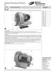
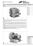
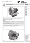
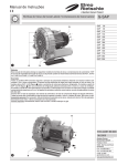
a built-in motor. A high efficiency two stage impellor is fitted on to the motorshaft. Models up to SAH / 4.8 kW (picture
)
use the motor fan for cooling. Models SAH / 5.5 kW and larger (picture ) have an additional cooling fan situated between
the motor and blower housing.
Air inlet and outlets have built-in silencers with the addition of a mesh disc on the suction silencer to protect the unit from
particles larger than 5 mm. Both the inlet and outlet have an inside connection thread corresponding to DIN ISO 228.
Versions of the SAH have on the suction side a solenoid valve and on the pressure side different connection flanges.
All the parts are made from a special aluminium alloy except for the motor rotor, stator and shaft.
Optional extras: As required, vacuum or pressure limiting valve, non-return valve, suction filter, motor starter, vacuum/
pressure change over valve.
Special versions: anti corrosive internal coating, gas tight version.
O
F
E
610.44498.40.000
F
E
08.2009
Gardner Denver
Deutschand GmbH
Postfach 1510
97605 Bad Neustadt/Saale
GERMANY
B
A
N
Fon +49 722 392 0
Fax +49 722 392 300
e-mail: er.de@
gardnerdenver.com
www.gd-elmorietschle.com
SAH (01)
SAH (02)
B
A
A
B
Q
Q
Suitability
The units SAH are suitable for use in the industrial field i.e. the protection equipments corresponds to EN DIN 294 table 4, for people
aged 14 and above.
SAH models can be operated as vacuum pumps or compressors. They are suitable for use with air of a relative humidity up to 90 % but not aggressive
gases. Gas tight versions are available. The tightness of each unit depends on the shaft seal. The shaft seal lifetime relates directly to the operating
conditions.
Dangerous mixtures (i.e. inflammable or explosive gases or vapours), water vapour or aggressive gases must not be handled.
Handling of inflammable or aggressive gases and vapours is only possible with special versions, if the safety instructions XE 1 are noted.
Operation in potentially explosive areas is not permissible.
The ambient and suction temperatures must be between 5 and 40° C. For temperatures outside this range please contact your
supplier.
For less aggressive media an internal protection coating can be utilised.
The maximum permissible pressure difference for vacuum or pressure depends upon the motor rating. This is indicated on the data plate (N) and
is shown in the data sheet for standard voltages and frequency:
SAH 25, SAH 45, SAH 55, SAH 75, SAH 95 see data sheet D 556/ 1 or D 656/ 1
SAH 155, SAH 215, SAH 235 see data sheet D 556/ 2 or D 656/ 2
SAH 275, SAH 355, SAH 505 see data sheet D 556/ 3 or D 656/ 3
Operating above these pressure differences the motor would be overloaded. As well as considering the maximum allowable pressure difference,
the amperage should also be checked against the data plate (N).
The loading of each unit depends on the specific gravity of the gas handled. Therefore when handling gases other than air, there are other pressure
difference limits to be considered. Please contact the supplier for further advice.
If it is possible for the flow to be throttled more than the allowed limits, then the use of vacuum or pressure limitation valves (optional extras) should
be considered.
The maximum permissible internal pressure is 3.5 bar(abs). With this pressure the performance is reduced.
For all applications where an unplanned shut down of the blower could possibly cause harm to persons or installations, the
corresponding safety backup system must be installed.
Handling and Setting up (pictures , and )
Pumps that have reached operating temperature may have a surface temperature at position (Q) of more than 70° C. WARNING! Do
Not Touch.
The blower, especially when the units are built-in, the cooling air entries (E) and the cooling air exits (F) must have a minimum distance of 10 cm
from any obstruction. The discharged cooling air must not be re-circulated.
SAH units can be operated in different positions.
SAH (01) models can be installed on a solid floor without bolting down. When installing SAH (02) models, i.e. motor vertically upwards, you must
secure against torque reaction on start-up. When fitting onto framework we recommend using anti-vibration mounts.
For installations that are higher than 1000 m above sea level there will be a loss in capacity. For further advice please contact your
supplier.
Installation (pictures , and )
For operating and installation follow any relevant national standards that are in operation.
1. Please remove transportation lock at (A) and (B).
2. When on vacuum operation connect the suction pipe at (A) and when on pressure operation connect the pressure pipe at (B).
Long and/or small bore pipework should be avoided as this tends to reduce the capacity of the blower.
If alternate vacuum or pressure is required, a changeover valve (ZWS) can be fitted (optional extra). In this case there is only one connection
for vacuum or pressure operation.
3. The electrical data can be found on the data plate (N) or the motor data plate. The motors correspond to DIN/VDE 0530 and have IP 55
protection and insulation class F. The connection diagram can be found in the motor terminal box (unless a special plug connection is fitted).
Check the electrical data of the motor for compatibility with your available supply (voltage, frequency, permissible current etc.).
4. Connect the motor via a motor starter. It is advisable to use thermal overload motor starters to protect the motor and wiring. All cabling used
on starters should be secured with good quality cable clamps.
We recommend that motor starters should be used that are fitted with a time delayed trip resulting from running beyond the amperage setting.
When the unit is started cold overamperage may occur for a short time.
When using a changeover valve (ZWS) the solenoid must also be connected. The voltage information on the solenoid should also be checked.
The electrical installation may only be made by a qualified electrician under the observance of EN 60204. The main switch must be
provided by the operator.
Initial Operation (pictures and )
Maximum number of starts per hour: 10
1. Initially switch the pump on and off for a few seconds to check the direction of rotation against the direction arrow (O).
2. When installed on the application and under the highest possible load conditions, the pressure differences of the unit may not be higher than the
max. allowable pressure differences shown on the data plate (N).
Note: If these values are exceeded when the unit is running on normal operating temperature an unloading of the unit is required by
utilising limitation valves ZBS, ZUV or ZBD (optional extra).
3. A comparison of the measured current amperage with the max. current amperage on the data plate (N) is not advisable, because the current
amperage depends on the voltage.
Potential risks for operating personnel
Noise Emission: The worst noise levels considering direction and intensity (sound power), measured according to DIN 45635 part 13 (as per 3.
GSGV), are shown in the table at the back. When working permanently in the vicinity of an operating unit we recommend wearing ear protection
to avoid any damage to hearing.
Maintenance and Servicing
When maintaining these units and where a situation exists where personnel could be hurt by moving parts or by live electrical parts
the blower must be isolated by totally disconnecting the electrical supply. It is imperative that the unit cannot be re-started during
the maintenance operation.
Do not maintain a blower that is at its normal operating temperature as there is a danger from hot parts.
In case of capacitor failure (1 ~ drive) replace the capacitor only with one that has identical rated value.
The pressure leading pipes must be ventilated before dismantling.
These side channel vacuum pumps and compressors need no maintenance apart from filtration.
The capacity of the blower can be reduced if the air inlet filters are not maintained correctly.
1. Mesh disc on the silencing housing:
Cleaning of this is possible through the opening (A) and (B).
2. Additional filter (optional extra):
The suction filter (ZAF) should be cleaned every 250 operating hours and changed every 3000 operating hours. Changing the filter: unscrew wing
nut (m1). Remove filter cover (h) and filter cartridge (f1). The filter cartridge can be cleaned by knocking out by hand or by using compressed air.
Replace the filter cartridge if necessary. Re-assemble in reverse order (see picture ).
The filter cartridge (f2) of the vacuum tight suction filter (ZVF) must be cleaned regularly, again depending upon the amount of contamination.
Cleaning can be achieved by washing or by blowing out with compressed air. Replace the filter cartridge if necessary. The cartridge (f2) can be
removed completely by undoing the relevant retaining clips (m2) (see picture ).
3. Bearings:
The units have bearings that are greased for life and require no maintenance.
Handling of inflammable or aggressive gases and vapours is only possible with special versions, if the safety instructions XE 1 are
noted.
ZAF
f1
h
m1
f2
ZVF
m2
Trouble Shooting:
1. Blower does not reach operating speed when starting:
1.1 Check that the incoming voltage and frequency corresponds with the motor data plate.
1.2 Check the connections on the motor terminal block.
2. Motor starter cuts out blower:
2.1 Problem as per 1.1 and 1.2.
2.2 Incorrect setting on the motor starter.
2.3 Motor starter trips too fast.
Solution: Use a motor starter with a time delay trip (version as per IEC 947-4).
2.4 Blower is overloaded, i.e. pressure difference is too high.
Solution: Increase the inlet or outlet diameter of the application, on pipework increase the diameter of the pipework, avoid restrictions in the
line. Limit the pressure difference by limitation valves (optional extra).
2.5 Motor rating selected was too small.
Solution: If available use a blower with the next motor size (exchange of the motor only is not possible).
3. Required pressure difference cannot be achieved:
3.1 Blower or motor rating selected, was too small.
3.2 Filters are contaminated.
3.3 Pressure loss into pipework too high.
Solution: Use bigger pipe diameter, avoid restrictions.
3.4 Leaks on the system.
4. Blower operates at an abnormally high temperature:
4.1 Ambient or suction temperature is too hot.
4.2 Pressure difference is higher than permitted.
4.3 Cooling air flow is restricted.
5. Exhaust noise (vacuum pump) or suction noise (compressor) are unacceptable:
Solution: Use an additional silencer ZGD (optional extra).
6. Change over valve ZWS (accessory) does not work:
6.1 Check that the incoming voltage and frequency correspond with the information on the solenoid.
6.2 Change over valve is contaminated.
Solution: Dismantle and clean.
Appendix:
Repair on Site: For all repairs on site an electrician must disconnect the motor so that an accidental start of the unit cannot happen.
All engineers are recommended to consult the original manufacturer or one of the subsidiaries, agents or service agents. The address of the nearest
repair workshop can be obtained from the manufacturer on application.
After a repair or before re-installation follow the instructions as shown under the headings ”Installation and Initial Operation”.
Lifting and Transport: To lift and transport units SAH 95 to SAH 505 the eye bolt on the pump must be used.
The weight of the blowers are shown in the accompanying table.
Storage: SAH units must be stored in dry ambient conditions with normal humidity. We recommend for a relative humidity of over 80% that the pump
units should be stored in a closed container with the appropriate drying agents.
Disposal: The wearing parts (as listed in the spare parts lists) should be disposed of with due regard to health and safety regulations.
Spare parts lists:
E 556/ 1 • SAH 25 —> SAH 155; SAH 215, 235, 275 (4 kW + 4,8 kW)
E 556/ 2 • SAH 215, 235, 275 (5,5 kW –> 9 kW); SAH 355; SAH 505
SAH
Noise level (max.)
Sound power
dB(A)
dB(A)
25
45
55
75
95
155
215
235
50 Hz
74
82
82,5
85
84
77
83,5
60 Hz
74
82
82,5
85
84
77
84
50 Hz
-
-
-
89
-
-
-
60 Hz
275
355
505
89
88
85
89
89
89,5
86
92
99
96
95
100
-
-
-
89
-
-
-
99
97
97
102
Weight (max.)
kg
16,5
20
24,5
26,5
34
52
65
88
110
136
213,5
Length (max.)
mm
337
348
390
390
417
449
552
620
647
734
777
Width
mm
246
255
286
286
336
392
438
458
471
540
540
Height
mm
269
298
324
324
410
447
489
545
567
620
620
8.08 / PM7
EC Declaration of Conformity 98/37/EC or 2006/42/EC*)
Hereby the manufacturer
confirms:
Gardner Denver Deutschland GmbH
P.O. Box 1510
D-97605 Bad Neustadt / Saale
that the machine:
of the:
Side channel blower
G-Series
G-SAH
Models
SAH 25, SAH 45, SAH 55, SAH 75, SAH 95, SAH 155,
SAH 215, SAH 235, SAH 275, SAH 355, SAH 505
is conform to the regulations of the guideline indicated above.
Furthermore, the designated product is conform to the regulations of the following guidelines:
2006/95/EC**)
Directive 2006/95/EC of the European Parliament and of the Council of 12 December 2006 on the
harmonisation of the laws of Member States relating to electrical equipment designed for use within
certain voltage limits (codified version)
The following harmonised standards have been applied:
EN 1012-1:1996
Compressors and vacuum pumps — Safety requirements — Part 1: Compressors
EN 1012-2:1996
Compressors and vacuum pumps — Safety requirements — Part 2: Vacuum pumps
Holger Krause
Name and address of the
EC person in charge for documentation***) P.O. Box 1510
D-97605 Bad Neustadt / Saale
Gardner Denver Deutschland GmbH
Bad Neustadt / Saale, 20.08.2009
ppa. Fred Bornschlegl
*)
**)
***)
The machine fulfils the material requirements of both guidelines
applies only to the guideline 98/37/EC
applies only to the guideline 2006/42/EC
664.44498.40.000