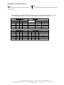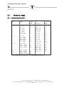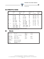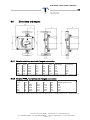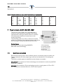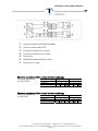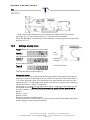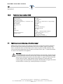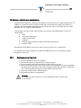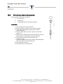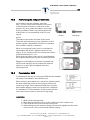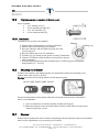
1
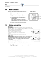
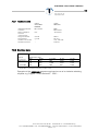
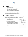
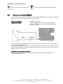
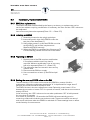
Variable area flow meters SGM Installation and Operating Instructions Variable area flow meters SGM A. Kirchner & Tochter GmbH Dieselstraße 17 · D-47228 Duisburg Fon: +49 2065 9609-0 · Fax: +49 2065 9609-22 Internet: www.kt-web.de · e-mail: [email protected] Version 1.7 Variable area flow meters SGM 1 Contents Foreword.................................................................................................................................................................. 4 2 Safety......................................................................................................................................................................... 4 2.1 Symbol and meaning................................................................................................................................ 4 2.2 General safty directions.......................................................................................................................... 4 2.3 Intended use ................................................................................................................................................ 4 2.4 Information for Operator and operating personnel .................................................................. 5 2.5 Regulations and directives .................................................................................................................... 5 2.6 Notice as required by the hazardous materials directive ...................................................... 5 3 Transport and storage...................................................................................................................................... 5 4 General ..................................................................................................................................................................... 6 4.1 Declarations of conformity with EC Directives ............................................................................ 6 4.2 Type series.................................................................................................................................................... 7 4.3 Description ................................................................................................................................................... 8 5 Installation ............................................................................................................................................................... 9 5.1 Preparation of the pipeline.................................................................................................................... 9 5.2 Installation in the pipeline....................................................................................................................... 9 6 Start-up..................................................................................................................................................................11 6.1 Measuring ranges..................................................................................................................................12 6.1.1 Version: stainless steel..............................................................................................................12 6.1.2 Version: PTFE / ceramics........................................................................................................13 6.2 Materials ....................................................................................................................................................13 6.3 Technical data SGM ..............................................................................................................................14 6.4 Dimensions and weights .....................................................................................................................15 6.4.1 Version: stainless steel with flanged connection...........................................................15 6.4.2 Version PTFE / ceramics with flanged connection .....................................................15 6.4.3 Version: stainless steel with female thread connection ............................................16 7 Plug-in contact unit IK1, IK2, IKS1, IKS2 ...............................................................................................16 7.1 Electrical connection.............................................................................................................................16 7.2 Setting the limit value ...........................................................................................................................18 7.3 Switching contact definition...............................................................................................................18 7.3.1 Technical data................................................................................................................................19 7.3.2 Electrical data ................................................................................................................................19 7.4 Installation..................................................................................................................................................20 7.5 Retrofitting a second contact...........................................................................................................20 A. Kirchner & Tochter GmbH Dieselstraße 17 · D-47228 Duisburg Fon: +49 2065 9609-0 · Fax: +49 2065 9609-22 Internet: www.kt-web.de · e-mail: [email protected] Version 1.7 Variable area flow meters 3 SGM 8 Electrical signal output SGM-EM ...............................................................................................................21 8.1 Compliance with IP degree of protection....................................................................................21 8.2 Electrical connection SGM-EM .........................................................................................................22 8.3 Technical data ESK2A..........................................................................................................................23 8.3.1 Self monitoring - diagnostics...................................................................................................23 8.4 Installation/replacement ESK2A....................................................................................................24 8.4.1 ESK2A as replacement: ............................................................................................................24 8.4.2 Installing an ESK2A .....................................................................................................................24 8.4.3 Replacing an ESK2A ...................................................................................................................24 8.4.4 Setting the zero and 100% value on the EM..................................................................24 8.4.5 Retrofitting an ESK2A, and its calibration........................................................................25 8.4.6 Changes and conversion ESK2A ..........................................................................................25 8.5 Hart™ communication with the ESK2A.......................................................................................26 9 Electrical signal output EM-PA Profibus.................................................................................................27 9.1 Bus cable....................................................................................................................................................27 9.2 Shielding and earthing..........................................................................................................................27 9.3 PROFIBUS-PA connection...................................................................................................................27 9.4 Technical data EM-PA ..........................................................................................................................28 9.4.1 Hardware .........................................................................................................................................28 9.4.2 Software ...........................................................................................................................................28 10 Flow totalizer EMZ.......................................................................................................................................29 10.1 Electrical connection........................................................................................................................29 10.2 Settings, display mode ....................................................................................................................30 10.3 Technical data, totalizer EMZ ......................................................................................................32 11 Maintenance and cleaning of the flow meter.................................................................................32 12 Service, retrofits and conversions.......................................................................................................33 12.1 Replacement of the float................................................................................................................33 12.2 Retrofitting a float damping system.........................................................................................34 12.3 Retrofitting the eddy-current brake..........................................................................................35 12.4 Flow totalizer EMZ ............................................................................................................................35 12.5 High-temperature version, indicator part..............................................................................36 12.5.1Installation..............................................................................................................................................36 12.6 Mounting the indicator ...................................................................................................................36 12.7 Disposal..................................................................................................................................................36 A. Kirchner & Tochter GmbH Dieselstraße 17 · D-47228 Duisburg Fon: +49 2065 9609-0 · Fax: +49 2065 9609-22 Internet: www.kt-web.de · e-mail: [email protected] Version 1.7 Variable area flow meters 4 SGM 1 Foreword These Installation and Operating Instructions are applicable to devices of Series SGM. Please follow all instructions and information given for installation, operation, inspection and maintenance. The Instructions form a component part of the device, and should be kept in an appropriate place accessible to the personnel in the vicinity of the location. Where various plant components are operated together, the operating instructions pertaining to the other devices should also be observed. Kirchner und Tochter accepts no liability for any damage or interruptions of operation resulting from human error, failure to comply with these Installation and Operating instructions, improper performance of installation and repair work, use of spare parts other than those from the original manufacturers or use of the SGM devices other than for the intended purpose 2 Safety 2.1 Symbol and meaning Safety notice This safety notice can be found at all hints on work safety in these assembly and operating instructions pointing out hazards for life and limb of persons. Further, this safety notice highlights safety hints in these operating instructions that point to regulations, guidelines or operating sequences that must be observed without fail. Non-observance may result in damages to or a destruction of the variable area flow meters and / or other parts of the installation. 2.2 General safty directions These Installation and Operating Instructions contain basic instructions for the installation, operation, inspection and maintenance of the flow meter. Failure to comply with these Instructions or improperly executed installation, wiring and repair work can lead to serious faults in the plant, giving rise to hazardous situations for "man and beast“ as well as damage to property. The operator is required to rule out potentially hazardous situations through voltage and released media energy. 2.3 Intended use The SGM devices are designed and intended for measuring the flow of compressible and incompressible fluids. They may only be installed between flanges in the pipeline. Select the SGM device model on the basis of the nominal diameter and nominal pressure at the site and also the kind of fluid product concerned; limit values are specified in the Section "Technical data" and should not be exceeded. Only devices that bear the "EEx" marking may be operated in hazardous areas. A. Kirchner & Tochter GmbH Dieselstraße 17 · D-47228 Duisburg Fon: +49 2065 9609-0 · Fax: +49 2065 9609-22 Internet: www.kt-web.de · e-mail: [email protected] Version 1.7 Variable area flow meters 5 SGM 2.4 Information for Operator and operating personnel Authorized installation, operating, inspection and maintenance personnel should be suitably qualified for the jobs assigned to them, and should receive appropriate training and instruction. All persons charged with assembly, mounting, operation, inspection and maintenance duties must have read and understood the operating instructions. Gaskets in contact with the fluid product must be replaced after all maintenance and repair work. 2.5 Regulations and directives In addition to the regulations mentioned below, pay attention without fail to the notices given in Section or operation in hazardous areas! All relevant regulations should be observed in respect of flow meter operation. These include in particular: Regulation concerning explosion protection (ExVO National, ATEX 95) Regulation concerning safe working conditions (Directive 1999/92/EC, ATEX 137) If appropriate, regulation concerning hazardous materials Accident prevention regulations Pressure Equipment Directive PED 97/23 EC 2.6 Notice as required by the hazardous materials directive In accordance with the law concerning handling of waste (critical waste) and the hazardous materials directive (general duty to protect), we would point out that all flow meters returned to Kirchner und Tochter for repair are required to be free from any and all hazardous substances (alkaline solutions, acids, solvents, etc.). Make sure that devices are thoroughly rinsed out to neutralize hazardous substances. 3 Transport and storage The SGM device is packed by the factory in packaging appropriate for transportation and storage. Transport and storage should be carried out solely in the original packaging. Protect the device against rough handling, impact, jolts, etc. A. Kirchner & Tochter GmbH Dieselstraße 17 · D-47228 Duisburg Fon: +49 2065 9609-0 · Fax: +49 2065 9609-22 Internet: www.kt-web.de · e-mail: [email protected] Version 1.7 Variable area flow meters 6 SGM 4 General 4.1 Declarations of conformity with EC Directives The variable area flow meter SGM meets all requirements of the EC Directives applicable to the product: EMC Directive (89/336/EEC) EN 61326 : 03/1997 +A1 : 04/1998 +A2 : 03/2001 ATEX (94/9/EC) EN 50014:1997 +A1 +A2 EN 50020:1994 DGRL (97/23/EC) A. Kirchner & Tochter GmbH Dieselstraße 17 · D-47228 Duisburg Fon: +49 2065 9609-0 · Fax: +49 2065 9609-22 Internet: www.kt-web.de · e-mail: [email protected] Version 1.7 Variable area flow meters 7 SGM 4.2 Type series SGM SGM-EM SGM-EMZ SGM-IK1 SGM-IK2 SGM-IKS1 SGM-IKS2 SGM-IK1-EM SGM-IK1-EMZ SGM-IK2-EM SGM-IK2-EMZ SGM-IKS1-EM SGM-IKS1-EMZ SGM-IKS2-EM SGM-IKS2-EMZ SGM EEx SGM-EM EEx SGM-IK1 EEx SGM-IK2 EEx SGM-IK1-EM EEx SGM-IK2-EM EEx All-metal device with electrical signal output with electrical signal output and totalizer with one inductive contact (SC3,5-N0-Y) with two inductive contacts (SC3,5-N0-Y) with one electronic contact (SB3,5-E2) with two electronic contacts (SB3,5-E2) with one inductive contact and with electrical signal output with one inductive contact and with electrical signal output and totalizer with two inductive contacts and with electrical signal output with two inductive contacts and with electrical signal output and totalizer with one electronic contact and with electrical signal output with one electronic contact and with electrical signal output and totalizer with two electronic contacts and with electrical signal output with two electronic contacts and with electrical signal output and totalizer all-metal device, explosion-proof design with electrical signal output, explosion-proof design with one inductive contact, explosion-proof design with two inductive contacts, explosion-proof design with one inductive contact and with electrical signal output, explosion-proof design with two inductive contacts and with electrical signal output, explosion-proof design A. Kirchner & Tochter GmbH Dieselstraße 17 · D-47228 Duisburg Fon: +49 2065 9609-0 · Fax: +49 2065 9609-22 Internet: www.kt-web.de · e-mail: [email protected] Version 1.7 Variable area flow meters 8 SGM 4.3 Description Indicator of modular design A module rack in the indicator accommodates all electrical options and the scale plate. The modules pertaining to the electrical options (see Figure) and the scale plate are inserted in the rack using the plug-in technique. The modules can be replaced or retrofitted without interrupting the process and without having to remove the pointer. If actual temperatures are higher than the max. allowable process temperatures for the standard version, the indicator can be (subsequently) adapted to suit the new operating conditions by using an adapter (HT version). Measuring parts made of various materials and fitted with different liners are available for the process media. The flow meter can be ordered with magnetic filter and/or float damper, and these can also be retrofitted. In the case of variable or pulsating flows, an eddy-current brake can additionally be installed to dampen the pointer. An indicator part of stainless steel is available on request. In Indicator optionally as hightemperature version Measuring part optionally with heating system Scale plate Electrical signal output EM Contacts IK1, IK2, IKS1, IKS2 Flow totalizer EMZ Module rack Indicator part optionally stainless steel A. Kirchner & Tochter GmbH Dieselstraße 17 · D-47228 Duisburg Fon: +49 2065 9609-0 · Fax: +49 2065 9609-22 Internet: www.kt-web.de · e-mail: [email protected] Version 1.7 Variable area flow meters 9 SGM 5 Installation 5.1 Preparation of the pipeline 5.2 Check the direction of flow in the pipe at the installation point of the flow meter. VA flow meters are as a rule only suitable for vertical installation, with the direction of flow being from bottom to top. For all other installation situations appropriate pipe bends need to be fitted in the existing pipeline to ensure vertical flow through the device from below. Straight unimpeded pipe runs should have a length equal to 5x DN upstream and 3x DN downstream of the installation location. Any control equipment, particularly in the case of gaseous media, should always be installed downstream of the flow meter. Refer also to Guideline VDE/VDI 3513 Sheet 3. The SGM type series can as a special version optionally be constructed for horizontal installation. If necessary, support the ends of the pipeline to prevent vibration from being transmitted to the flow meter. Clean by blowing or flushing out the pipes leading to the device before connecting up. Prepare the installation point before starting to mount the flow meter. Make sure the sealing faces are correctly spaced apart and in true alignment. On no account should the VA flow meter be used to pull the ends of the pipeline together (stress-free installation!). Installation in the pipeline 1. Check that the device is free from solid foreign bodies. 2. Use bolts and gaskets (to be provided by customer) in keeping with the pressure rating of the connection flanges and the operating pressure. 3. The inside diameter of the flanges differs from standard dimensions. Flange gaskets standard DIN 2690 can be applied without restriction. 4. Align gaskets, tighten nuts with the torques relevant to the appropriate pressure rating. A. Kirchner & Tochter GmbH Dieselstraße 17 · D-47228 Duisburg Fon: +49 2065 9609-0 · Fax: +49 2065 9609-22 Internet: www.kt-web.de · e-mail: [email protected] Version 1.7 Variable area flow meters 10 SGM For measuring parts with PTFE liner and for measuring parts with ceramic liner and PTFE sealing face, tighten the flange bolts with the following max. torques: DIN 2501 DN 15 25 50 80 100 Nominal size to ... ANSI B 16.5 PN in. lbs 40 ½” 150/300 40 1” 150/300 40 2” 150/300 16 3” 150/300 16 4” 150/300 Stud bolts 4 x M 12 4 x M 12 4 x M 16 8 x M 16 8 x M 16 DIN 2501 DN 15 25 50 80 100 Nominal size to ... ANSI B 16.5 PN in. lbs 40 ½” 150/300 40 1” 150/300 40 2” 150/300 16 3” 150/300 16 4” 150/300 Max. torque DIN ANSI 150 lbs Nm Nm ft·lbf 9.8 7.1 5.2 21 15 10 57 41 41 47 34 70 67 36 50 DIN ANSI 150 lbs 4 x ½” 4 x ½” 4 x 5/8” 4 x 5/8” 8 x 5/8” 300 lbs 4 x ½” 4 x 5/8” 8 x 5/8” 8 x ¾” 8 x ¾” ft·lbf 3.8 7.2 30 51 36 A. Kirchner & Tochter GmbH Dieselstraße 17 · D-47228 Duisburg Fon: +49 2065 9609-0 · Fax: +49 2065 9609-22 Internet: www.kt-web.de · e-mail: [email protected] Version 1.7 Variable area flow meters 11 SGM 6 Start-up A minimum operating pressure (inlet pressure) is necessary for operation of the device. Process medium Liquids Gases (without damper) Gases (with damper) pressure drop : operating pressure 1:2 1:5 1:2 Pressure drop: see Flow Tables The device must be properly installed before it is started up. 1. Test the device connections. 2. To set the flow: pressurize the pipes by slowly opening the shutoff valves. On liquid service, carefully evacuate the pipeline. 3. Check that all components are leak-tight and, if necessary, retighten threaded joints or screw connections. Applies to gases in particular: avoid pulsation of the medium. Basically, vary the flow with the aid of adjusting valves so that the float is not subjected to pressure surges (e.g. from solenoid valves), otherwise the measuring part could sustain damage. Devices for flowmetering of gases can be equipped with a gas damping system to avoid possible float oscillation due to compression. Should the float nevertheless tend to oscillate, this can be remedied by installing a throttle valve or suitable aperture plate downstream of the device, see Guideline VDE/VDI 3513 Sheet 3. A float damping system is recommended for gas measurements. A. Kirchner & Tochter GmbH Dieselstraße 17 · D-47228 Duisburg Fon: +49 2065 9609-0 · Fax: +49 2065 9609-22 Internet: www.kt-web.de · e-mail: [email protected] Version 1.7 Variable area flow meters 12 SGM 6.1 Measuring ranges 6.1.1 Version: stainless steel Size 15 / 1/2“ Stainless steel float Water Pressur e drop l/h mbar 2.5 – 25 26 4.0 – 40 26 6.3 – 63 26 10 – 100 26 16 – 160 26 25 – 250 26 40 – 400 28 63 – 630 32 100 – 1000 50 25 / 1“ 63 – 630 100 – 1000 160 – 1600 250 – 2500 400 – 4000 630 – 6300 32 33 34 38 45 103 2) 50 / 2“ 630 – 6300 1000 – 10000 1600 – 16000 2500 – 25000 74 77 84 104 80 / 3“ 2500 – 25000 4000 – 40000 6300 – 63000 10000– 100000 68 89 120 220 100 / 4“ Air m3/h i.N.1) 0.065 – 0.65 0.1 – 1 0.15 – 1.5 0.22 – 2.2 0.36 – 3.6 0.55 – 5.5 1.0 – 10 1.4 – 14 1.8 – 18 2.8 – 28 1,4 – 14 2.2 – 22 3.5 – 35 5.0 – 50 8.0 – 80 11.0 – 110 17.0 – 170 8.0 – 80 11.0 – 110 15.0 – 150 23.0 – 230 35.0 – 350 60.0 – 600 35.0 – 350 40.0 – 400 Pressure drop mbar 21 21 21 21 21 21 21 22 38 50 24 24 25 26 30 78 103 2) 13 13 13 60 69 104 16 16 Devices used for gas measurement: float damping system recommended! 1) i.N.: = at STP (0°C and 1.013 bar abs.) 2) 300mbar with damping system A. Kirchner & Tochter GmbH Dieselstraße 17 · D-47228 Duisburg Fon: +49 2065 9609-0 · Fax: +49 2065 9609-22 Internet: www.kt-web.de · e-mail: [email protected] Version 1.7 Variable area flow meters 13 SGM 6.1.2 Version: PTFE / ceramics Size 15 / 1/2“ 25 / 1“ 50 / 2“ 80 / 3“ 100 / 4“ PTFE float Water l/h 2.5 – 25 4.0 – 40 6.3 – 63 10 – 100 16 – 160 25 – 250 40 – 400 63 – 630 100 – 1000 160 – 1600 250 – 2500 Pressure drop mbar 65 66 66 68 72 86 111 70 80 108 158 400 – 4000 630 – 6300 1000 – 10000 1600 – 16000 2500 – 25000 4000 – 40000 81 110 170 81 95 100 Ceramic float Water l/h 3 – 30 5 – 50 7 – 70 13 – 130 20 – 200 25 – 250 Pressure drop mbar 62 64 66 68 70 72 50 – 500 70 – 700 110 – 1100 160 – 1600 250 – 2500 450 – 4500 630 – 6300 1100 – 11000 1600 – 16000 2500 – 25000 55 60 70 82 100 70 80 110 70 85 Air m³/h i.N.1) Pressure drop mbar 0.18 – 1.8 0.24 – 2.4 0.40 – 4.0 0.65 – 6.5 0.90 – 9.0 64 66 68 70 72 1.8 – 18 2.2 – 22 3.0 – 30 5.0 – 50 7.5 – 75 14 – 140 20 – 200 35 – 350 55 60 70 82 100 70 80 110 Devices for gas measurement: float damping system recommended! 1) i.N. = at STP (0°C and 1.013 bar abs.) 6.2 Materials Version Measuring tube/float SGM / VA SS / SS SGM / C4 Hastelloy C4/Hastelloy C4 SGM / PTFE SGM / PTFE / K SGM / TFM / K Indicator: Scale casing Pointer Scale Window PTFE1)/PTFE Temperatur -80°C ... + 300°C - 80°C ... + 300°C 70°C PTFE /ceramics 150°C TFM /ceramics 250°C 1) 1) Ambiente ≤120°C ≤120°C ≤70°C ≤70°C ≤120°C Aluminium, enamelled Aluminium, enamelled Aluminium, coated Float glass 1) Measuring tube of stainless steel (1.4404) with liner A. Kirchner & Tochter GmbH Dieselstraße 17 · D-47228 Duisburg Fon: +49 2065 9609-0 · Fax: +49 2065 9609-22 Internet: www.kt-web.de · e-mail: [email protected] Version 1.7 Variable area flow meters 14 SGM 6.3 Technical data SGM Accuracy class Standard (VA/C4) alt. (PTFE/ceramics) Indicator part Scale Scale length Turndown ratio Type of protection, indicator part Version: SS Allowable working pressure DN 15, DN 25, DN 50 DN 80, DN 100 Version: PTFE Allowable working pressure Connections 1.6 to VDE/VDI 3513 2.5 to VDE/VDI 3513 in physical units, e.g.: l/h, m3/h 90 mm 1:10 IP 67, NEMA 4X PN 40 PN 16 same as SS version Flanges to DIN 2501 (EN 1092-1), On request: ANSI B 16.5, JIS, DIN 11851, threaded pipe joint to ISO 228 A. Kirchner & Tochter GmbH Dieselstraße 17 · D-47228 Duisburg Fon: +49 2065 9609-0 · Fax: +49 2065 9609-22 Internet: www.kt-web.de · e-mail: [email protected] Version 1.7 Variable area flow meters 15 SGM 6.4 Dimensions and weights 6.4.1 Version: stainless steel with flanged connection DN 15 25 50 80 100 PN 40 40 40 16 16 Dim. L 250 250 250 250 250 A 70.5 70.5 57.5 57.5 57.5 B 107 119 132 148 158 Ød 20 32 65 89 114 Weight kg DIN flanges 3.5 5.0 8.2 12.2 14.0 with heating 4.8 6.7 10.4 14.0 16.6 Overall length for devices with female thread to ISO 228: 300 mm; to ANSI B 16.5 (from 3“ / 300lbs): 300 mm 6.4.2 Version PTFE / ceramics with flanged connection DN 15 25 50 80 1001) PN 40 40 40 16 16 Dim. L 250 250 250 250 250 A 70.5 70.5 57.5 57.5 57.5 B 107 119 132 148 158 Ød 20 32 65 89 114 Weight kg DIN flanges 3.5 5.0 10.0 13.0 15.0 1) PTFE only Overall length for devices with female thread to ISO 228: 300 mm; to ANSI B 16.5 (from 3“ / 300lbs): 300 mm A. Kirchner & Tochter GmbH Dieselstraße 17 · D-47228 Duisburg Fon: +49 2065 9609-0 · Fax: +49 2065 9609-22 Internet: www.kt-web.de · e-mail: [email protected] Version 1.7 Variable area flow meters 16 SGM 6.4.3 Version: stainless steel with female thread connection DN 15 15 15 15 25 25 G G½ ½“ NPT ¾“ NPT G1 G1 1“ NPT Dim. L 300 300 300 300 300 300 A 70.5 70.5 70.5 70.5 70.5 70.5 B 107 107 107 107 119 119 Ød 20 20 20 20 32 32 Weight kg 3.5 3.5 3.5 3.5 5.0 5.0 7 Plug-in contact unit IK1, IK2, IKS1, IKS2 The VA flow meter SGM can be equipped with a maximum of two electronic contacts. The contact operates with a slot type initiator which is actuated inductively by the half-round metal vane on the measuring pointer. The switching points are set by means of a contact pointer, the position of the contact pointer at the same time serving to visually indicate the set limit value. Contact types: SC3,5-N0-Y 2-wire technology (NAMUR) SB3.5-E2 3-wire technology 7.1 1 limit contact 2 contact pointer 3 plug connector 4 terminal 5 terminal socket Electrical connection Remove the housing cover of the indicator part to connect the plug-in contact unit. The terminals (4) are of the plug-in type and can be detached for connecting the cables. The built-in contact types are specified on the indicator nameplate. SC3,5-N0-Y limit contacts in 2-wire technology are connected in conformity with DIN EN 50227 (NAMUR). SB3.5-E2 limit contacts in 3-wire technology require a supply power of 10 to 30 V DC. They can be connected direct to a PLC control system. A. Kirchner & Tochter GmbH Dieselstraße 17 · D-47228 Duisburg Fon: +49 2065 9609-0 · Fax: +49 2065 9609-22 Internet: www.kt-web.de · e-mail: [email protected] Version 1.7 Variable area flow meters 17 SGM ➀ ➁ ➂ ➃ ➄ ➅ ➆ 2-wire limit switch SC3,5-NO-Y NAMUR 3-wire limit switch SB3,5-E2 Terminal connection min contact Terminal connection max contact 3-wire load NAMUR isolated switching amplifier 3-wire power supply Electrical connection of limit contact in 2-wire technology Terminal assignment Contact MIN for SC3,5-N0-Y Plug colour black Labelling 2-wire technology 1 – 2 + 3 Electrical connection of limit contact in 3-wire technology Terminal assignment Contact MIN for SB3,5-E2 Plug colour black Labelling 3-wire technology 1 + 2 3 – MAX grey 4 5 – + MAX grey 4 5 + 6 6 – A. Kirchner & Tochter GmbH Dieselstraße 17 · D-47228 Duisburg Fon: +49 2065 9609-0 · Fax: +49 2065 9609-22 Internet: www.kt-web.de · e-mail: [email protected] Version 1.7 Variable area flow meters 18 SGM 7.2 Setting the limit value Setting is made directly via the contact pointer (2): Scale opening 1. 2. 3. 4. Unscrew housing cover Move scale to the side Slightly loosen locking screw (1) Slide scale back up to point where it snaps into place 5. Set contact pointer (2) to the desired switching point. After setting, the pointer (2) should be tightened down again with locking screw (1). 6. Replace housing cover and screw down. 7.3 Switching contact definition MIN contact An alarm is generated when the pointer vane (1) dips into the slot. When the pointer vane is outside the slot type initiator, a wire break will also cause an alarm to be initiated. No wire break identified by SB3,5-E2! Option: version as Maximum contact In the alarm status the vane is located outside the slot. Wire break identification not available in this case. MAX contact An alarm is generated when the pointer vane (1) dips into the slot (and dampens this initiator). When the pointer vane is outside the slot type initiator, a wire break will also cause an alarm to be initiated. No wire break identified by SB3,5-E2! Option: version as Minimum contact In the alarm status the vane is located outside the slot. Wire break identification not available in this case. In the IK2 / IKS2 version, both contact systems are equipped. A. Kirchner & Tochter GmbH Dieselstraße 17 · D-47228 Duisburg Fon: +49 2065 9609-0 · Fax: +49 2065 9609-22 Internet: www.kt-web.de · e-mail: [email protected] Version 1.7 Variable area flow meters 19 SGM 7.3.1 Technical data Switching element function Nom. voltage U0 Current consumption: Flag not sensed Flag sensed Continuous current No-load current I0 2-wire SC3,5-N0-Y NAMUR NC contact 3-wire SB3,5-E2 8V PNP NO contact 10 to 30 V ≥3 mA ≤1 mA – – ≤0.3 V Ub - 3 V max. 100 mA ≤15 mA 7.3.2 Electrical data Built-in equipment SC3,5-N0-Y SJ3,5-SN Identification data Ui[V] Ii[mA] ≤16 ≤25 ≤16 ≤52 ≤16 ≤25 Pi [mW]* ≤64 ≤169 ≤64 Ci [nF] ≤150 ≤150 ≤30 Li [uH] ≤150 ≤150 ≤100 * dependent on the isolation switching amplifier used Operation of the SC3,5-N0-Y contact requires the use of an isolation switching amplifier, e.g. Pepperl + Fuchs Series KF .. -SR2 ... . A. Kirchner & Tochter GmbH Dieselstraße 17 · D-47228 Duisburg Fon: +49 2065 9609-0 · Fax: +49 2065 9609-22 Internet: www.kt-web.de · e-mail: [email protected] Version 1.7 Variable area flow meters 20 SGM 7.4 Installation 1. Unscrew housing cover, (if necessary, remove flow totalizer EMZ) 2. Bring contact pointers (1) together in the middle. 3. Undo locking screw (2) of contact pointers 4. Slide the plug-in contact unit into the third rail up to the point where the half-round (3) encloses the pointer spindle. The terminals of the plug-in contact unit are of the plug-in type and can be detached for connection of the cables. To comply with the IP degree of protection, please consult the directions given in Section 8.1. 7.5 Retrofitting a second contact The retrofit kit consists of the required contact pointer and integrated contact. The connecting cable is fitted with the integrally moulded plug. To install, it may be necessary to unplug the flow totalizer first. 1. Unplug the contact unit from the module rack. 2. Remove locking screw (1). Caution: Spring (2) is under pressure 5. Assemble contact pointers (4), slide rings (3), spring (2) and locking screw as shown in the drawing. 6. The second ring (Item 3) is already provided in the version with one contact. 7. Insert plug connector of the contact (blue) into the socket on the circuit board. 8. Plug in and connect up the contact unit. A. Kirchner & Tochter GmbH Dieselstraße 17 · D-47228 Duisburg Fon: +49 2065 9609-0 · Fax: +49 2065 9609-22 Internet: www.kt-web.de · e-mail: [email protected] Version 1.7 Variable area flow meters 21 SGM 8 Electrical signal output SGM-EM The indicator part of the SGM-EM with the ESK2A module supplies a current of 4 to 20 mA in two-wire connection that is proportional to the instantaneous flow rate. Transmission is force-free and hysteresis-free. The ESK2A has been factory-calibrated on the basis of the flow measuring range. The calibration values, used for linearization of the indicator, are stored in a memory module (EEPROM). The required power supply is a functional extra-low voltage with protective separation (galvanic) in accordance with VDE 0100 Part 410. All instruments (indicators, recorders) connected to the measuring circuit are connected in series and together may not exceed the maximum external resistance (see 8.3). The ESK2A features polarity reversal protection. 8.1 Compliance with IP degree of protection To comply with the IP degree of protection for built-in electrical equipment, please pay attention to the following points: 1. After inserting the connection cable, tighten the cap nut on the cable gland. 2. Close off all unused cable glands with blanking plugs. 3. Do not kink cables directly at the cable gland. 4. Provide a water drip point. 5. Ensure incoming cables are not subjected to mechanical loads. Cable glands / screwed cable glands: Thread M 16x1.5 M 20x1.5 M 16x1.5 M 20x1.5 Material PA PA nickel-plated brass nickel-plated brass Wire diameter 5 - 10 mm 8 - 13 mm 5 - 9 mm 10 - 14 mm Protection* IP 68 - 5 bar IP 68 - 5 bar IP 68 - 5 bar IP 68 - 10 bar Comment Standard * Degree of protection restricted to screwed cable gland only A. Kirchner & Tochter GmbH Dieselstraße 17 · D-47228 Duisburg Fon: +49 2065 9609-0 · Fax: +49 2065 9609-22 Internet: www.kt-web.de · e-mail: [email protected] Version 1.7 Variable area flow meters 22 SGM 8.2 Electrical connection SGM-EM The connection terminals of the ESK2A module in the SGM-EM indicator part are of plug-in design and can be removed to connect up the cables. Terminal connection Type of connection pluggable; < 2,5 mm2 2 wire current sink - polarity reversal protection only for connection to extra-low voltage according to SELV or PELV ESK2A Be careful by conceptual design in connection with other instruments (e.g. supply units or process control engineering). It is possible that internal connection of ground, earth-connections or equipotential bonding will generate voltage drops, which leads to malfunction of the instrument. For this case a signal processor is required. Connections at hazardous locations Before installation at hazardous location read the Supplementary Installation and Operating Instruction. A. Kirchner & Tochter GmbH Dieselstraße 17 · D-47228 Duisburg Fon: +49 2065 9609-0 · Fax: +49 2065 9609-22 Internet: www.kt-web.de · e-mail: [email protected] Version 1.7 Variable area flow meters 23 SGM 8.3 Technical data ESK2A Power supply Measuring signal 24 V Dc 4 to 20 mA for 0 to 100% flow value > 20.8 mA for alarm status Power effect Ext. resistance dependence Temperature effect Max. ext. resistance/load Ambient temperature < 0,1% <0,1% <5μA/K 250*... to 800 ohms -25° C...+60° C * These values are to be conformed to as minimum values in the case of HARTTMcommunication. 8.3.1 Self monitoring - diagnostics Setting-up operation as well as operation there are several cyclic diagnostic functions to get operational reliability. An error detection generates an output signal (high) of > 21 mA. Additional information are given via HART™ command #48. Information and warnings will not generate an error output current. Diagnostic functions (control): Plausibility of FRAM data Plausibility of ROM data Working range of internal reference voltages Signal detection of the measuring range of the magnet sensors Temperature compensation of the magnet sensors Calibration corresponding the application Plausibility of counting value Plausibility of physical unit and selected unit A. Kirchner & Tochter GmbH Dieselstraße 17 · D-47228 Duisburg Fon: +49 2065 9609-0 · Fax: +49 2065 9609-22 Internet: www.kt-web.de · e-mail: [email protected] Version 1.7 Variable area flow meters 24 SGM 8.4 Installation/replacement ESK2A 8.4.1 ESK2A as replacement: The ESK2A has been standardized by the factory, so that e.g. a replacement can be carried out without requiring recalibration. If necessary, the zero and the 100% value can be readjusted. Loss of accuracy has to be expected (Class 1.6 → Class 2.5). 8.4.2 Installing an ESK2A 1. Assembly is based on the plug-in technique. 2. Insert the push-in lugs of the ESK2A under the two pins of the baseplate (1). 3. Using slight pressure, press the ESK2A on to the spring bolt (2) until it locks into place and fastens the ESK2A securely. 4. When the ESK2A is retrofitted, the fixing strap (3) is automatically pushed out and can be removed. 8.4.3 Replacing an ESK2A 1. Replacement of the EM requires recalibration if compliance with the accuracy class is required. Without recalibration, loss of accuracy has to be expected (Class 1.6 →Class 2.5). 2. The calibration data are stored in the memory module used. 3. Disconnect the EM from supply. 4. Use a screwdriver to lever up the EM and pull it out. 8.4.4 Setting the zero and 100% value on the EM The zero and the 100% value can be set on the ESK2A by means of built-in pushbuttons. When the pushbutton behind the "4“ is depressed for longer than 5 seconds, the measured value will skip to 4mA. The ESK2A is then in the zero adjustment mode. Optionally, press button "4" for downward correction or button "20" for upward correction, until the zero amounts to exactly 4.00mA . In the same way, the 100% value can be set when pushbutton "20“ is held pressed for more than 5 seconds. If no button is pressed for 10 seconds, the ESK2A will automatically go to its measuring mode and include the corrections made. These corrections are stored and remain valid even when the ESK2A is switched off. These settings have no effect on the linearity of measurement. A. Kirchner & Tochter GmbH Dieselstraße 17 · D-47228 Duisburg Fon: +49 2065 9609-0 · Fax: +49 2065 9609-22 Internet: www.kt-web.de · e-mail: [email protected] Version 1.7 Variable area flow meters 25 SGM 8.4.5 Retrofitting an ESK2A, and its calibration Retrofitting is only possible if the indicator had been supplied "with EM preparation". The required calibration data are specified on the indicator cover. To carry out linearization requires the conversion program KroVaCal and a HART™ modem that is connected to the serial interface of the PC. Linearization of the ESK2A is carried out in 3 steps: Recording of the measuring points Linearization of the characteristic by means of the PC Storage of the linearization data in the EEPROM via the serial interface Recording of measuring points: Recording of the measuring points should be carried out at the main scale marks in order to obtain the best possible linearization result. These points can be approached in three different ways: dynamic setting: setting the flow value (original medium or a reference medium established by conversion) static setting: lifting up the float (not the pointer!) until the pointer indicates the main scale value. For all approached measuring points, both the respective flow value and also the associated current value of the ESK2A should be noted down. 8.4.6 Changes and conversion ESK2A If any change is required to the measuring range, the process temperature, the process medium, the density, the viscosity, or the pressure, this can be carried out by Kirchner und Tochter. A. Kirchner & Tochter GmbH Dieselstraße 17 · D-47228 Duisburg Fon: +49 2065 9609-0 · Fax: +49 2065 9609-22 Internet: www.kt-web.de · e-mail: [email protected] Version 1.7 Variable area flow meters 26 SGM 8.5 Hart™ communication with the ESK2A HART™ communication is not obligatory in order to operate the ESK2A. If HART™ communication is carried out with the EM, it will in no way affect the analog transmission of measured values (4...20mA)…. HARTTM Protocol revision 5.9 Exception: in multidrop operation. In multidrop operation a maximum of 15 devices with HART™ function can be operated in parallel, their current outputs being switched to the inactive state (I approx. 4mA). ESK2A Where a HART™ communicator (Type Fisher Rosemount, Model 275) or a PC with HART™ modem is used, the series-connected resistance (Rext.) must be greater than 250 ohms. In this mode, the supply power should be a minimum of 18 V. The communicator or PC, whichever is applicable, is connected up as shown in the drawing above. It can optionally be operated via the power terminals of the ESK2A (2) or via a seriesconnected external resistor (1). When the ESK2A is operated together with the totalizer, HART™ communication is possible in accordance with the following wiring diagram: The totalizer itself cannot be read or operated by means of the HART™ communication ! ESK2A A. Kirchner & Tochter GmbH Dieselstraße 17 · D-47228 Duisburg Fon: +49 2065 9609-0 · Fax: +49 2065 9609-22 Internet: www.kt-web.de · e-mail: [email protected] Version 1.7 Variable area flow meters 27 SGM 9 Electrical signal output EM-PA Profibus 9.1 Bus cable The definitions of the FISCO Model apply only provided the bus cable used conforms to the following specifications: R´ = 15...150 Ohm/km L´ = 0,4...1 mH/km C´ = 80...200 nF/km. 9.2 Shielding and earthing For optimum electromagnetic compatibility of systems it is extremely important for the system components, and particularly the bus cables connecting up the components, to be shielded and that, electrically speaking and if at all possible, these shields form a continuous envelope. 9.3 PROFIBUS-PA connection For connection of the bus cable, see Figure on the right. Connect the cable cores to D and D┴ (polarity reversal has no effect). The cable shield should be connected with minimal length to the functional earth FE. The equipotential bonding conductor should be connected to the device (if necessary, via the outer earth U-clamp terminal of the indicator part). Bus connection A. Kirchner & Tochter GmbH Dieselstraße 17 · D-47228 Duisburg Fon: +49 2065 9609-0 · Fax: +49 2065 9609-22 Internet: www.kt-web.de · e-mail: [email protected] Version 1.7 Variable area flow meters 28 SGM 9.4 Technical data EM-PA 9.4.1 Hardware Physics Supply voltage via 2-wire Bus connection: Base current Starting current FDE Accuracy to VDI / VDE 3513 Measured value resolution Temperature effect to IEC 1158-2 and the FISCO Model 9 to 32 V DC 12 mA < base current < 18 mA 1.6 < 0.1% of upper range value < 0.05% / K of upper range value 9.4.2 Software GSD (device master file) supplied on diskette Device profile Function blocks Flow (AI0) complete realization of Profile B, V3.0 Totalizer (TOT0) Totalizer (TOT1) Address range SAP`s DD Operator control optionally for volume or mass flow rate Default units: Qv [m3/h]; Qm [kg/h] Volumetric meter - default unit: [m3] Mass flow - default unit: [kg] 0-126, default 126 (set slave address is supported) Service_Access_Points 1 Device-Description DD for PDM via Profibus-PA (no local operator control) A. Kirchner & Tochter GmbH Dieselstraße 17 · D-47228 Duisburg Fon: +49 2065 9609-0 · Fax: +49 2065 9609-22 Internet: www.kt-web.de · e-mail: [email protected] Version 1.7 Variable area flow meters 29 SGM 10 Flow totalizer EMZ The flow totalizer EMZ in 3-wire technology can be built into the indicator part in combination with the electrical current output EM. The flow totalizer EMZ is not suitable for hazardous environments. A 6-digit display indicates the total flow value, and can be switched over to the instantaneous flow value in 0 ... 100% . Supply 11/12 and current loop 12/13 are not galvanically separated! If the current loop is not needed, a shorting jumper has to be connected to terminals 12/13. A galvanically separated pulse output P+ and P- supplies one pulse for every counter advance indicated. If the pulse output is not needed, its terminals may remain unused. Data are saved automatically in the event of a power failure. The flow totalizer has been factory-set according to data specified in the order and requires no adjustment! The conversion factor for the totalizer, unless otherwise ordered, is set relative to the measuring range so that the summated value (in Liter, m³ etc.) can be read directly. Button 1 Button 2 Button 3 Reset R 10.1 Display Flow in % Summated value Conversion factor The stored total value is deleted Comment Totalizing continues in the background. e.g. Litres or m³ Standard: 10% of Q100 Electrical connection The supply power required is a protective extra-low voltage (PELV) to VDE 0100 Part 410. All instruments (recorders, indicators, etc.) connected to the measuring circuit are connected in series and may not exceed the max. external resistance of 720 ohms. The supply voltage US of max. 30 VDC is connected to terminals 11+ and 12at the totalizer module. A. Kirchner & Tochter GmbH Dieselstraße 17 · D-47228 Duisburg Fon: +49 2065 9609-0 · Fax: +49 2065 9609-22 Internet: www.kt-web.de · e-mail: [email protected] Version 1.7 Variable area flow meters 30 SGM ESK2A * When galvanically separated current evaluation modules (PLC) are used at terminals 12/13, the supply power (11/12) should not be earthed. When the EM signal is needed only for the totalizer, a shorting jumper is required at terminal 12/13. 10.2 Settings, display mode Reset Deletes the stored summated value Button 1 Example with decimal point and one decimal place Button 2 Example without decimal points Taste 3 Example flow in [%] totalizing counter conversion factor The first two decimal points light up Conversion factor The conversion factor is factory-set and always based on the measuring range so that the current summated value can be read out at any time. Conversion factor = 10% of the full-scale range. This allows the summated value to be read from the display directly 1:1. If the measuring range is not known, e.g. spare parts delivery, a conversion factor of 1000 is factory-set. If a change or correction to the conversion factor is necessary, this factor can be changed by pressing Button 2 at the moment the supply voltage is switched on. A factor between 1 and 1099 can be set using Buttons 1 to 3. Factor 0 is not defined. Button 1: ones Button 2: tens Button 3: hundreds and thousands The Reset button is used to confirm and terminate entries. The totalizer then goes into the display mode previously selected. A. Kirchner & Tochter GmbH Dieselstraße 17 · D-47228 Duisburg Fon: +49 2065 9609-0 · Fax: +49 2065 9609-22 Internet: www.kt-web.de · e-mail: [email protected] Version 1.7 Variable area flow meters 31 SGM Totalizer content The totalizer content is saved in the case of a power failure and can be set to zero with the RESET button during operation. Totalizer overflow is signalled by all decimal points lighting up. Zero reset is carried out by pressing the RESET button. Adjustment Adjustment is not required since the totalizer has been factory-adjusted to the current measuring range. Should nevertheless readjustment be required, this can be done as follows: 1. at the moment of switching on, keep the RESET button depressed until three decimal points light up. 2. Set 4.00 mA and then press Button 1 until digit 0 appears 3. Set 20.00 mA and then press Button 3 until digits 100 appear 4. Exit the adjustment mode by pressing Button 2. A. Kirchner & Tochter GmbH Dieselstraße 17 · D-47228 Duisburg Fon: +49 2065 9609-0 · Fax: +49 2065 9609-22 Internet: www.kt-web.de · e-mail: [email protected] Version 1.7 Variable area flow meters 32 SGM 10.3 Technical data, totalizer EMZ Auxiliary power Rext. current loop Power consumption Max. external resistance / load Pulse output Auxiliary power Max. current Max. power loss T on T off U on U off Pulse value Ambient temperature Indication error 11 24 V DC 0 ... 600 ohms max. 2 W 0 to 720 ohms, dependent on supply voltage terminal P+, P24 V DC 50 mA 250 mW fixed pulse width 80 ms dependent on flow Ub – 3 V 0V 1 pulse = 1 display totalizer advance = 1 flow unit (1 Litre , 1 m³ ....) - 25°C to + 65°C < 1% of value indicated, one display unit at maximum Maintenance and cleaning of the flow meter Within the scope of routine operational maintenance of the plant and the pipelines, the flow meter should also be inspected for dirt accumulation, signs of corrosive wear, mechanical wear and damage to the measuring tube and the indicator. We recommend that inspections be carried out at least once a year. To clean the device it must be removed from the pipeline. Attention! Pressurized pipes to be depressurized before removing the measuring part. In connection with devices used for flow measurement of aggressive media, appropriate safety precautions should be taken in regard to residual liquids in the measuring part. New gaskets should always be used when the measuring part is reinstalled in the pipeline. Electrostatic charges should be avoided when surfaces (e.g. viewing window) are cleaned! A. Kirchner & Tochter GmbH Dieselstraße 17 · D-47228 Duisburg Fon: +49 2065 9609-0 · Fax: +49 2065 9609-22 Internet: www.kt-web.de · e-mail: [email protected] Version 1.7 Variable area flow meters 33 SGM 12 Service, retrofits and conversions All devices with defects or deficiencies should be sent direct to our repair department. To enable our customer service facility to deal with complaints and repairs as quickly as possible, we would kindly request you to coordinate the return of devices with our sales department, Tel. +49 (0) 2065-96090. The variable area flow meter with indicator part can be retrofitted with a number of components: float float damping system eddy-current brake contacts ESK2A, when indicator ordered "with EM preparation" totalizer EMZ Retrofitting of the EM-PA can only be carried out by means of a recalibration. An assembly kit is also available to enable the SGM device to be converted to a hightemperature version. 12.1 Replacement of the float 1. 2. 3. 4. Remove the device from the pipeline. Remove the upper circlip from the measuring part. Remove upper float stop and float from the measuring part. Insert new float into the centre hole in the lower float stop and place it together with the upper float stop in the measuring part. Note that the upper float guide rod must be guided through the centre hole of the float stop. 5. Insert the circlip in the measuring part. 6. Re-install the device in the pipeline. Caution! An additional measuring error is to be expected unless recalibration is carried out. A. Kirchner & Tochter GmbH Dieselstraße 17 · D-47228 Duisburg Fon: +49 2065 9609-0 · Fax: +49 2065 9609-22 Internet: www.kt-web.de · e-mail: [email protected] Version 1.7 Variable area flow meters 34 SGM 12.2 Retrofitting a float damping system The complete retrofit kit consists of: 2 circlips (3) 1 collet (4) 1 damping cylinder with float stop (2) Installation: 1. Remove device from the pipeline. 2. Remove upper circlip (1) from measuring part. 3. Take upper float stop and float (5) out of the measuring part. 4. Fasten circlip (3) in the lower groove on the float guide rod. 5. Slide ceramic collet (4) on to the float guide rod and fasten with the circlip (3) in the upper groove. 6. Insert float in the lower float guide in the measuring part. 7. Install the supplied damping cylinder with integrated float stop (2) in the measuring part. 8. Insert upper circlip (1). 9. Re-install device in the pipeline. A. Kirchner & Tochter GmbH Dieselstraße 17 · D-47228 Duisburg Fon: +49 2065 9609-0 · Fax: +49 2065 9609-22 Internet: www.kt-web.de · e-mail: [email protected] Version 1.7 Variable area flow meters 35 SGM 12.3 Retrofitting the eddy-current brake In connection with the indicator part with EM / current output and contactors, be aware of the fact that short-time movements of the pointer may occur when the eddy-current brake is being installed. These may possibly generate a false alarm or cause peaking of the current output. Brake Clamping screw The eddy-current brake consists of two parts: The brake with retaining ring can clipped on to the pointer cylinder independent of built-in components such as EM, contacts or totalizers. When mounting the brake, bear in mind that the slot between the brake magnets measures only approx. 3 mm und the aluminium pointer vane has a material thickness of 1 mm. Check that the pointer vane can be moved between the magnets without coming into contact with them. Slightly turn the eddy-current brake clockwise and screw in the clamping screw. Adjust the brake as shown on on the right and tighten down the clamping screw. 12.4 Flow totalizer EMZ In combination with the current output EM, the flow totalizer can also be retrofitted in the indicator part When ordering the totalizer as a retrofit kit, please specify the device data (as shown on the right) as well as the measuring range. These data will enable the new scale with totalizer display cutout to be prepared in readiness for installation! The flow totalizer is then preset with the conversion factor based on the measuring range. Installation: 1. 2. 3. 4. Slide out the existing scale. Slide the flow totalizer unit on to the middle rail of the module rack. Then slide the new scale into the module rack. While sliding over the totalizer display, lift the scale slightly until the scale cutout forms a frame around the totalizer display. A. Kirchner & Tochter GmbH Dieselstraße 17 · D-47228 Duisburg Fon: +49 2065 9609-0 · Fax: +49 2065 9609-22 Internet: www.kt-web.de · e-mail: [email protected] Version 1.7 Variable area flow meters 36 SGM 12.5 High-temperature version, indicator part Items supplied: 1 no. sealing ring (1) 3 nos. fastening screws (2) 1 no. HT extension (3) 2 nos. distance bolts (4) 12.5.1 Installation The device can remain in the pipeline. Magnet Sealing ring 1. Note pointer position before removing indicator! 2. Detach both nuts fastening the indicator. 3. Remove indicator with its fastening clips from the measuring part. 4. Remove plastic cap from HT extension. 5. Position ring (1) exactly in the groove on the HT extension. 6. Fasten HT extension with the three screws (2) to reverse side of indicator. 7. Screw distance bolts (4) to the threaded pin on measuring part and tighten down (width A/F: 14 mm). 12.6 Mounting the indicator Position the indicator with fastening clips on the distance bolts (4), fit washers and tighten down with nut (max. 8 Nm). Caution: be aware of mounting position of the fastening clips: DN15, DN25 DN50, DN80, DN100 Compare the position of the pointer with the previously recorded value indicated. If there is any deviation: 1. Use a screwdriver to hold the pointer spindle (see Figure). 2. Move the pointer to the recorded value counter to the friction forces of the measuring pointer mount. 12.7 Disposal Please help to protect the environment by disposing of the workpieces used in accordance with current regulations or by continuing to use them. A. Kirchner & Tochter GmbH Dieselstraße 17 · D-47228 Duisburg Fon: +49 2065 9609-0 · Fax: +49 2065 9609-22 Internet: www.kt-web.de · e-mail: [email protected] Version 1.7 Variable area flow meters SGM The variable-area flow meter SGM meets all requirements of the EC Directives applicable to the product. EMC Directive (89/336/EEC) EN 61326 : 03/1997 +A1 : 04/1998 +A2 : 03/2001 ATEX (94/9/EC) EN 50014:1997 +A1 +A2 EN 50020:1994 DGRL (97/23/EC) The Kirchner equipment has been tested in compliance with the applicable CE-regulations of European Community. The respective declaration of conformity is available on request. The KIRCHNER QM-System is certified in accord with DIN-EN-ISO 9001:2000. The quality is systematically adapted to the continuously increasing demands. A. Kirchner & Tochter GmbH Dieselstraße 17 · D-47228 Duisburg Fon: +49 2065 9609-0 · Fax: +49 2065 9609-22 Internet: www.kt-web.de · e-mail: [email protected] Version 1.7