Download Mounting and Operating Instructions TV gateway -

Transcript
Mounting and
Operating Instructions
TV gateway
2610 ..
Table of contents
Device description ............................................... 3
Connection to a television ................................... 4
Connection to a BK system (cable connection)... 5
Connection to the world of IP ............................. 6
Switching the TV gateway on externally ............. 7
Mounting ........................................................... 8
Operating elements ............................................. 9
Changing display time ....................................... 10
Start-up menu Structure of the menu interface ........................ 11
Start-up menu ................................................... 12
Start-up.............................................................. 17
Examples
TV gateway and TC-gateway ............................. 18
TV gateway and audio home station ................. 20
TV gateway and video home station ................. 22
Multi-flat house with satellite system................ 24
Technical data................................................... 27
Warranty........................................................... 27
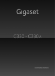
Device description
The TV gateway transmits the video picture of the Gira
door communication system to a television.
By using the appropriate converter, the video picture of
the colour camera can be fed to an antenna system or the
HomeServer.
1
8
2
7
3
6
4
5
The TV gateway is comprised of the following components:
1 TV gateway bus coupler
2 Audio connection cable (6-pole)
3 TV gateway connection cable (2-pole)
4 TV gateway insert
5 SCART adapter
6 TV gateway top unit
7 Blind cover plate
8 Cover frame (not included in the scope of delivery)
SELV rating at the interfaces
Only components with a SELV rating may be connected
to the interfaces of the TV gateway (ET terminals and
switch output). The SELV rating is to be ensured when
feeding the cable and during connection.
3
Connection to a television
In this case, the television is connected to the TV gateway directly via the SCART connection.
The SCART connection of the TV gateway features a
switch output to support automatic switching to the AV
channel.
As soon as an incoming door call is made, the picture of
the colour camera automatically switches to the television (the television must be switched on).
Audio HS
Phone
Resistance=no
TV-Gateway
TV
VV
Power supply
i
TC-Gateway
Video control
device
Video door
station
Function of the TV gateway
The TV gateway only transmits the picture of the video
door station. The door conversation is held via a home
station or a telephone connected to the TC-gateway.
Topologically, the TV gateway then functions as a video
home station. For this reason, the same rules apply for
setting the terminating resistance and the use of video
distributors as for a video home station.
4
Connection to a BK system (cable connection)
In a multi-flat house, the video signal can be patched in
to an antenna system via the TV gateway.
The FBAS signal of the TV gateway must be converted to
a UHF signal before it can be fed into the antenna
system. A conventional AV modulator is required for this
purpose.
A specific channel is assigned in this case. When an
incoming door call is made, this channel must be
selected manually to view the video picture.
Audio HS
TC-Gateway
Phone
TV
Power
supply
Audio HS
TC-Gateway
Phone
TV
Power
supply
Audio HS
TC-Gateway
VV
TV
Power supply
BK-Amplifier
Cable
connection
AV-Modulator
TV-Gateway
Resistance=no
Video control
device
Video door
station
5
Connection to the world of IP
In conjunction with conventional video servers, the video
picture of the colour camera can also be displayed via the
Gira HomeServer, for example.
In addition to the HomeServer, the picture can also be
displayed on a computer, PDA, mobile telephone (UMTS,
MMS and GPRS services) and IP picture phones. Image
memory can also be implemented in conjunction with
the HomeServer.
HomeServer
Audio HS
Phone
Resistance=no
TV-Gateway
LAN
IP-Modulator
VV
Power
supply
TC-Gateway
Video control Video door
station
device
Switch output
The switch output of the TV gateway can be used by EIB
components (e.g. EIB push button interface) if necessary.
It is closed if the TV gateway has been activated (e.g.
after a call button is pressed).
The top and side break-out sections of the TV gateway
top unit must be removed (e.g. with a screwdriver)
before the switch output can be used.
ZV
BUS
ET
EIB push
button
interface
EIB-actuator
Switch input
6
Switch output
Switching the TV gateway on externally
SELV rating at the interfaces
Only components with a SELV rating may be connected
to the ET terminals of the TV gateway and the add-on
module. The SELV rating is to be ensured when feeding
the cable and during connection.
ZV
BUS
ET
Push button
Push buttons at the switch input (ET terminals)
The TV gateway can be switched on manually via the ET
terminals without prior initiation by door call. Thus the
picture of the colour camera can be displayed on the television at any time. Switching to several other cameras
is also possible. Connect a push button (NO contact) to
the ET terminals of the bus coupler.
To switch on or change camera views, press the push
button briefly; to switch off, press and hold the push
button (for contact closing times, see "Technical data",
Page 27).
Add-on module
Specific individual colour cameras can be selected and
switched on with an add-on module.
For this purpose, the add-on module is connected to the
bus coupler of the TV gateway with the 6-pole connection cable.
To switch on/change views, the corresponding push button must be pressed; to switch off, the push button must
be pressed and held (for contact closing times, see
"Technical data", Page 27).
Choke
ZV
BUS
7
Mounting
Attention
Installation and mounting of electrical devices may only
be carried out by a qualified electrician.
The TV gateway is installed in two conventional flushmounted panel boxes:
Choke
1. Insert the 6-pole connection cable into a system slot
of the TV gateway insert.
2. Insert the 2-pole connection cable into the video slot
of the TV gateway insert.
The choke of the 2-pole connection cable must be
located near the TV gateway insert.
3. Guide both connection cables into the panel box of
the TV gateway bus coupler.
ZV 4. Install the TV gateway insert.
BUS
5. Insert both connection cables into the TV gateway
bus coupler.
6. Connect the 2-wire bus to the BUS terminals of the
TV gateway bus coupler.
i
Bus coupler jumpers
On the TV gateway, the accompanying wire jumpers
must be attached between BUS and ZV.
7. Install the TV gateway bus coupler.
8. Set the cover frame in place and attach the TV gateway top unit and the blind cover plate to the flushmounted inserts.
i
Colour identification on the inserts and
top units
To prevent mix-ups, the TV gateway inserts and top units
are marked with a white dot and the bus coupler and
blind cover plate are marked with a yellow dot.
8
Operating elements
On/Off button
With the On/Off button, you can switch the TV gateway
and the corresponding colour camera on and off, and
switch between several colour cameras.
To switch on, briefly press the On/Off button. If several
colour cameras are present, the last active camera is
switched on.
To switch off, press and hold the On/Off button for
approx. 3 seconds.
If several colour cameras are connected, the On/Off button is also used to switch to the next camera;
after a door call, the picture from the camera at the door
station that initiated the door call is displayed first.
By briefly pressing the On/Off button, the display
switches to the next camera and then the next. When the
last camera is reached, the next press of the button
returns you to the first camera.
The number of the active camera (e.g. Cam 1) is displayed in the video picture for five seconds.
In menu mode, the On/Off button functions as a "back
button", i.e. pressing this button moves you one step
back in the menu or the menu is exited.
Menu
Control button (menu)
Control button with 5-way navigation for the directions
up, down, left, right (if installed properly) and centre.
When the TV gateway is switched on, you activate the
setting menu by pressing the centre of the control button.
You can navigate in the menu with the control button.
The arrows in the display and the action features in the
lower area of the video picture indicate the available navigation directions of the control button.
9
Changing the display time
The display time specifies the amount of time after which
the TV gateway automatically switches off after manual
switch-on.
The display time of the TV gateway is set in the
"Display time" menu.
You access the menu by pressing the centre of the control button with the TV gateway switched on.
DISPLAY TIME
30 S
,,OK
10
Display time
Default setting: 30 s
Select the display time of the TV gateway in the range of
20 to 120 s with the control button . Confirm the disBACK
play time you have selected by pressing the centre of the
control button (OK).
Start-up menu - Structure of the menu interface
Menu title
Selection
symbol
Scroll symbols
MENU

FREQUENCY
RESISTOR
 ILLUMINATION 
,,OK
Action feature
control button
BACK
Action feature
On/Off button
Menu title
The menu title indicates the current menu item (main
menu in this case).


Scroll symbols
The scroll symbols indicate the direction in which you
can navigate with the control button.

Selection symbol
The selection symbol indicates the menu item that you
have just selected with the control button. In this example, pressing the control button in the centre calls up the
"Illumination" menu item.
Action feature On/Off button
The presently available On/Off-button actions are displayed here.
In this example, you can exit the main menu with the
On/Off button.
Menu
Action feature control button
The presently available control-button actions are displayed here.
In this example, you can navigate up/down () and call
up the selected menu item (Resistance) by pressing the
centre of the control button (OK).
11
Start-up menu
You access the Start-up menu by pressing the control
button with the TV gateway switched on and while the
Gira door communication system is in programming
mode.
To start programming mode, press the "Systemprog."
button at the control device for 3 seconds until the yellow
LED next to the "Systemprog." button flashes.
The following setting options are available in the Start-up
menu:
PRIORITY
MAIN DISPLAY
SUB DISPLAY
,,OK
●
If several TV gateways or TFT displays are operated in a
home, a maximum of one TV gateway or TFT display may
BACK
be set as the main display. The rest are designated sub
displays.
The main display is automatically switched on with an
incoming door call.
The sub displays are only switched on with a call acceptance at the home station after a door call or via the
On/Off button.
Frequency
FREQUENCY

::::::::■::::
,,OK
Priority
Default setting: Main display

BACK
i
Only active with assigned camera
The "Frequency" menu item is only active if a colour
camera has already been assigned to the TV gateway.
The optimum video signal frequency of the currently
active transfer path is set with the control button   for
fine tuning of the video signal between the camera and
the TV gateway.
If the "Frequency" menu item is exited via "Back", altered
settings are not accepted.
i
Setting for several TV gateways
and colour cameras
The frequency setting applies only for the connection
from the active TV gateway to the active colour camera.
This means that the frequency for the transfer path
between the TV gateway and colour camera must be set
individually at each TV gateway if several TV gateways
and/or colour cameras are present.
12
RESISTOR
 YES
NO
,,OK
●
BACK
Resistor
Default setting: Yes
The terminating resistance of the TV gateway is activated/deactivated here.
This setting is dependent on the topology.
More detailed information on this is available in the system description included with the video control device.
i
Terminating resistance and video distributor
Topologically, the TV gateway functions as a video home
station. For this reason, the same rules apply for setting
the terminating resistance and the use of video distributors as for a video home station.
ILLUMINATION
 AUTO
OFF
,,OK
Illumination
●
BACK
i
Only active with assigned camera
The "Illumination" menu item is only active if a colour
camera has already been assigned to the TV gateway.
Default setting: Auto
The behaviour of the field of view illumination of the camera is set here. The corresponding colour camera must be
selected before setting.
Auto: The field of view illumination of the colour camera
is switched on for a door call or with manual switching
on of the TV gateway if the ambient brightness is less
than 1 lux.
Off: The field of view illumination always remains
switched off.
i
Setting for several TV gateways
and colour cameras
The illumination setting only applies for the active TV
gateway and colour camera.
This means that if several TV gateways and/or colour
cameras are present, the illumination must be set individually for each colour camera at every TV gateway.
13
DISPLAY
 ON
OFF
,,OK
●
Display
Default setting: On
Here you set whether the TV gateway can be switched on
via the
BACK
On/Off button.
On: The TV gateway is switched on after the call button
is pressed or via the On/Off button.
Off: The TV gateway is only switched on after a door call.
Manual switch-on via the On/Off button is not possible
with this setting.
i
Setting with several TV gateways
If several TV gateways are present, this setting must be
made at all TV gateways.
LANGUAGE
 DEUTSCH
ENGLISH
,,OK
14
●
BACK
Language
Default setting: Deutsch (German)
The menu language German or English can be selected
here.
TEACH IN
 GET CALL..... +
SET STATIONS. ●
Teach In
Door stations, home stations and TC-gateways are
assigned to the TV gateway here.
R:2.20 S:1.48
Get call: A call button is assigned to the TV gateway.
,,OK
BACK
R: 2.20 specifies how many call buttons are already
taught in and how many can be assigned in total.
In this example, the two call buttons have been assigned
to the TV gateway; a total of 20 call buttons can be
assigned.
"+" indicates that a call button has been successfully
assigned (the R:2.20 counter is incremented by 1 here as
well).
"-" indicates that the call button has not been successfully assigned.
Set stations: An entire door or home station or a TCgateway is assigned to the TV gateway.
S: 1.48 specifies how many stations are already assigned
and how many can be assigned in total.
In this example, one station has been assigned to the TV
gateway; a total of 48 stations can be assigned.
The dot "●" indicates the activated function. As soon as a
station has been successfully assigned, the dot "●"
changes to "+" (the S:1.48 counter is incremented by 1
as well).
i
Function activation time
The "Set stations" function remains active until programming mode is exited or deactivated by pressing the control button.
15
DEFAULT SET.
 TV GATEWAY...
DELETE CAMS.. ●
CLR CALLS... ●
CLR STATIONS. ●
,,OK
BACK
Default set.
The settings are restored to the default settings here.
A differentiation is made between:
TV gateway: All menu items except for "Illumination" are
reset to the default setting.
The assignments to colour cameras, call buttons and stations are retained.
Delete cams: All camera assignments are deleted here.
The settings for frequency and illumination are reset.
"Delete cams" is then required, for example, if a defective
camera is to be removed from the system.
Once this function has been executed, the cameras must
be reregistered: For this purpose, start programming
mode at the control device and press any call button at
all door stations with a colour camera for 3 seconds.
Important: Go through the door stations in the order to
be displayed later in the video picture (e.g. Main door
cam 1, Side door cam 2 etc.).
Clr calls: All assignments to the call buttons are deleted
here.
Clr stations: The assignments to entire door stations,
home stations or TC-gateways are deleted here.
The dot "●" next to the menu entries indicates that the
respective memory is still empty, i.e. no call buttons have
been taught in yet, for example.
Version
The current software version of the processor is displayed here.
VERSION
02.00

DISPLAY TIME
30 S
,,OK
16
BACK
Display time
Default setting: 30 s
The display time specifies the amount of time the
TV gateway stays on after a manual switch-on.
BACK
Using the  control button, select the switch-on time
of the TV gateway in the range of 20 to 120 s. Confirm
the display time you have selected by pressing the centre
of the control button (OK).
Start-up
i
TFT display
If a television is not available for set-up, a TFT display
can be attached to the TV gateway insert and used as a
display.
The TV gateway can be used as a display for several
home stations or TC-gateways. For this reason, four
basic programming steps (each greyed out in the following start-up examples) are required when setting up the
TV gateway:
I.
Assignment of the call buttons of the video door station
to the home station/TC-gateway.
II. Assignment of the video door station to the TV gateway.
III. Assignment of the home station/TC-gateway to the TV
gateway.
IV. Setting of the TV gateway: frequency, illumination,
resistance.
Behaviour of the TV gateway during start-up
If the TV gateway has not yet been assigned a video door
station, it remains switched off during normal operation.
For testing purposes, the main menu of the TV gateway
can be switched on manually in programming mode. This
is helpful when searching for a channel when feeding in
the video signal to an antenna system, for example.
1. Start programming mode at the control device by
pressing the "Systemprog." button for 3 seconds until
the LED next to the button starts flashing.
2. Briefly press the On/Off button on the TV gateway.
✓ The main menu of the TV gateway is displayed for the
duration of programming mode.
i
Switching the TV gateway menu on
If the TV gateway has already been assigned a colour
camera, the menu interface is started by pressing the
control button in the centre while the TV gateway is
switched on.
17
Example: TV gateway and TC-gateway
Intercom communication to the door station is handled
by the TC-gateway, whereas the TV gateway displays the
video picture of the colour camera before and during the
door conversation.
Phone
Resistance=yes
TV-Gateway
TV
Power
supply
18
TC-Gateway
Video control
device
Video door
station
Start-up
1. Start programming mode at the control device by
pressing the "Systemprog." button for 3 seconds until
the LED next to the button starts flashing.
2. Press the call button on the door station for
3 seconds. Release the call button after the brief
acknowledgement tone.
I.
✓ You will hear a long acknowledgement tone.
3. Assign the door call buttons to the TC-gateway
(see TC-gateway operating instructions).
4. Press the call button on the door station again for
3 seconds. Release the call button after the brief
acknowledgement tone.
II.
✓ You will hear a long acknowledgement tone.
5. Select the "Teach in" menu in the Start-up menu of
the TV gateway and confirm the item "Get call"
there.
R:1.20
✓ In the "Teach in" menu of the TV gateway, the counter
of taught-in call buttons is incremented by 1.
6. Select the "Teach in" menu in the Start-up menu of
the TV gateway and confirm the item "Set stations"
there.
III.
7. Start command mode at the TC-gateway (see TCgateway operating instructions).
8. Execute a switching function at the TC-gateway by
pressing the hash key on the connected telephone
and pressing a number not assigned to a door station.
✓ You will hear the long acknowledgement tone of the
TC-gateway.
S:1.48
✓ In the "Teach in" menu of the TV gateway, the counter
of taught-in stations is incremented by 1.
9. Exit the menu item "Set stations" on the TV gateway.
IV.
10.Make the settings (e.g. frequency, illumination) in the
Start-up menu of the TV gateway.
19
Example: TV gateway and audio home station
Intercom communication to the door station is handled
by the audio home station, whereas the TV gateway displays the video picture of the colour camera before and
during the door conversation.
Audio HS
20
VV
TV-Gateway
Resistance=no
TV
Video control
device
Video door
station
Start-up
1. Start programming mode at the control device by
pressing the "Systemprog." button for 3 seconds until
the LED next to the button starts flashing.
2. Press the call button on the door station for
3 seconds. Release the button after the brief
acknowledgement tone.
I.
✓ You will hear a long acknowledgement tone.
3. Assign the door call button to the audio home station by pressing the button
for 3 seconds.
Release the button after the brief acknowledgement
tone (see system manual).
✓ You will hear a long acknowledgement tone.
4. Press the call button on the door station again for
3 seconds. Release the button after the brief
acknowledgement tone.
II.
✓ You will hear a long acknowledgement tone.
5. Select the "Teach in" menu in the Start-up menu of
the TV gateway and confirm the item "Get call"
there.
R:1.20
✓ In the "Teach in" menu of the TV gateway, the counter
of taught-in call buttons is incremented by 1.
6. Select the "Teach in" menu in the Start-up menu of
the TV gateway and confirm the item "Set stations"
there.
III.
7. Press the
button on the home station for
3 seconds. Release the button after the brief
acknowledgement tone.
✓ You will hear a long acknowledgement tone.
S:1.48
✓ In the "Teach in" menu of the TV gateway, the counter
of taught-in stations is incremented by 1.
8. Exit the menu item "Set stations" on the TV gateway.
IV.
9. Make the settings (e.g. frequency, illumination) in the
Start-up menu of the TV gateway.
21
Example: TV gateway and video home station
If the TV gateway is operated alongside the video home
station, two different applications are possible:
TV gateway as the main display
The TV gateway is switched on with a door call and displays the video picture on the television. If the door conversation is accepted at the video home station, the TV
gateway is switched off and the video picture is displayed on the TFT display (sub display) of the video home
station.
TV gateway as an sub display
During a door call, the video picture is displayed on the
TFT display (main display) of the video home station. If
the TV gateway is switched on manually, the TFT display
of the video home station is switched off.
i
Only one main display per flat
Only one device may be operated as the main display
when video home stations or TV gateways are called up
in parallel. All other displays are sub displays.
Video HS
Resistance=yes
i
TV-Gateway
Resistance=no
TV
Video control
device
Video door
station
Do not assign the video home station
to the TV gateway
A video home station may never be assigned to the TV
gateway.
22
Start-up
1. Start programming mode at the control device by
pressing the "Systemprog." button for 3 seconds until
the LED next to the button starts flashing.
2. Press the call button on the door station for
3 seconds. Release the button after the brief
acknowledgement tone.
I.
✓ You will hear a long acknowledgement tone.
3. Assign the door call button to the video home station by pressing the button
for 3 seconds.
Release the button after the brief acknowledgement
tone (see system manual).
✓ You will hear a long acknowledgement tone.
4. Press the call button on the door station again for
3 seconds. Release the button after the brief
acknowledgement tone.
II.
✓ You will hear a long acknowledgement tone.
5. Select the "Teach in" menu in the Start-up menu of
the TV gateway and confirm the item "Get call"
there.
R:1.20
IV.
✓ In the "Teach in" menu of the TV gateway, the counter
of taught-in call buttons is incremented by 1.
6. Select the "Main display"/"Sub display" setting for the
TFT display and at the TV gateway in the "Priority"
menu, depending on the application (see Page 22).
7. Make the settings (e.g. frequency, illumination) in the
Start-up menu of the TV gateway.
i
Only one main display per flat
Only one device may be operated as the main display
when video home stations or TV gateways are called up
in parallel. All other displays are sub displays.
23
Example: Multi-flat house with satellite system
In a multi-flat house, the video signal is fed to the
antenna system via a modulator. The flats feature audio
home stations or video home stations.
i
Note
When feeding the video signal into an antenna system,
the video picture can be displayed on all televisions that
are switched on when a door call is made.
To see the video picture, the corresponding channel
must be selected on the television.
Satellite receiver
Audio HS
TV
Satellite receiver
Audio HS
TV
Satellite receiver
TV
LNB
Multi-Switch
AV-Modulator
i
Audio HS
VV
TV-Gateway
Resistance=no
Video control
device
Video door
station
Applications in a multi-flat house
Two different applications are possible in a multi-flat
house:
• All call buttons of the door station are to activate the
TV gateway (see Page 25).
• Selected call buttons of the door station are to activate the TV gateway (see Page 26).
24
Start-up - All call buttons of the door station are to
activate the TV gateway
i
Assigning door station to the TV gateway
In a multi-flat house, all call buttons of the door station
can be assigned via the "Set stations" menu item so that
each call button does not need to be assigned individually.
1. Start programming mode at the control device by
pressing the "Systemprog." button for 3 seconds until
the LED next to the button starts flashing.
I.
2. Assign the corresponding call buttons to all home
stations as described in the system manual.
II.
3. Select the "Teach in" menu in the Start-up menu of
the TV gateway and confirm the item "Set stations"
there.
4. Press any call button on the door station for 3 seconds. Release the button after the brief acknowledgement tone.
✓ You will hear a long acknowledgement tone.
S:1.48
✓ In the "Teach in" menu of the TV gateway, the counter
of taught-in stations is incremented by 1.
5. Press the
button of each audio home station
one after another for 3 seconds each. Release the
button after the brief acknowledgement tone.
III.
✓ You will hear a long acknowledgement tone.
S:2.48
✓ In the "Teach in" menu of the TV gateway, the counter
of taught-in stations is incremented by 1.
6. Repeat Step 5 until all home stations are assigned to
the TV gateway.
7. Exit the menu item "Set stations" on the TV gateway.
IV.
8. Make the settings (e.g. frequency, illumination) in the
Start-up menu of the TV gateway.
25
Start-up - Selected call buttons of the door station are
to activate the TV gateway
1. Start programming mode at the control device by
pressing the "Systemprog." button for 3 seconds until
the LED next to the button starts flashing.
I.
2. Assign the corresponding call buttons to all home
stations as described in the system manual.
II.
3. Press each of the call buttons on the door station
that are to be assigned to the TV gateway for 3 seconds each (up to 20 call buttons can be temporarily
stored with each step). Release each call button after
the brief acknowledgement tone.
✓ You will hear a long acknowledgement tone.
4. Select the "Teach in" menu in the Start-up menu of
the TV gateway and confirm the item "Get call"
there.
R:1.20
✓ In the "Teach in" menu of the TV gateway, the counter
of taught-in call buttons is incremented by 1.
5. Repeat Step 4 until all call buttons are assigned to
the TV gateway.
6. Select the "Teach in" menu in the Start-up menu of
the TV gateway and confirm the item "Set stations"
there.
III.
7. Press the
button on all audio home stations for
3 seconds each. Release the button after the brief
acknowledgement tone.
✓ You will hear a long acknowledgement tone.
S:1.48
✓ In the "Teach in" menu of the TV gateway, the counter
of taught-in stations is incremented by 1.
8. Exit the menu item "Set stations" on the TV gateway.
IV.
26
9. Make the settings (e.g. frequency, illumination) in the
Start-up menu of the TV gateway.
Technical data
Power supply:
via system bus
Connections:
2 two-wire bus screw terminals
2 auxiliary power screw terminals
4 system bus connector strips
2 video connector strips
2 switch input screw terminals
SELV rating (ET terminals)
2 switch output screw terminals
1 SCART jack
Colour system:
PAL
Temperature range: -5 °C to + 50 °C
Contact closing times:
short:
< 1.5 sec.
long:
> 2.0 sec.
Number of devices that can be taught in:
Stations:
max. 48 (home station,
door station, TC-gateway)
Call buttons:
max. 20
Protection type:
IP 20
Switch output:
50 μA to 1.6 A, 24 V AC/DC
SELV rating at the interfaces
Only components with a SELV rating may be connected
to the interfaces of the TV gateway (ET terminals and
switch output). The SELV rating is to be ensured when
feeding the cable and during connection.
Warranty
The warranty is provided in accordance with statutory
requirements via the specialist trade.
Please submit or send faulty devices postage paid
together with an error description to your responsible
salesperson (specialist trade/installation company/electrical specialist trade).
They will forward the devices to the Gira Service Center.
27
Postfach 1220
42461 Radevormwald
Deutschland
Tel +49 (0) 21 95 / 602 - 0
Fax +49 (0) 21 95 / 602 - 191
www.gira.de
[email protected]
41 09 02 31/11
Gira
Giersiepen GmbH & Co. KG
Elektro-InstallationsSysteme