1
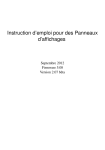
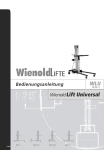
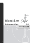
OPERATING INSTRUCTIONS zentralsolist 300 CONTENTS 1 | Information on this instruction manual………………………………………………………………………….…….….3 1.1 Signs and symbols used..………………………………………………….....…..3 1.1 General signs and symbols..……………………………………………..…...….3 1.1.2 Warning signs…………....………………………………………………………3 2 | General safety instructions ................................................................................... 4 1.1 Authorised use..…………………………………………………….…….……….4 2.1.1 Proper use ................................................................................................... 4 2.1.2 Hazards due to improper handling .............................................................. 4 2.1.3 Residual hazards ......................................................................................... 5 2.2 General safety indications.............................................................................. 5 3 | Description .......................................................................................................... 6 3.1 System components......................................................................................... 6 3.2 Functioning and operation ............................................................................... 7 4 | Commissioning .................................................................................................... 7 4.1 Transport .......................................................................................................... 7 4.2 Assembly ........................................................................................................... 8-11 4.3 Initial operation ................................................................................................. 11 4.4 Connecting users ............................................................................................... 12 4.5 During operation .............................................................................................. 12-13 5 | Storage.................................................................................................................... 14 6 | Maintenance ........................................................................................................... 14 7 | Troubleshooting ................. ................................................................................... 15 8 | Technical data ........................................................................................................ 15 2 1 | INFORMATION ON THIS INSTRUCTION MANUAL 1.1 Signs and symbols used Read these operating instructions before using the device for the first time. 1.1.1 General signs and symbols This symbol indicates general information provided for your better overall understanding. 1.1.2 Warning signs Warning signs identify obstacles and hazards. Danger of electric shock This symbol identifies activities which present the risk of electric shock, with possible fatal consequences. Hazardous areas This symbol identifies activities which may have various dangerous consequences. 3 2 | GENERAL SAFETY INSTRUCTIONS 2.1 Authorised use The photovoltaic island system is based on state-of-the-art science and technology. It satisfies the safety regulations applicable at the time of going to market, subject to its application according to authorised use. The system is delivered with an EC Declaration of Conformity and bears the EC conformity mark. 2.1.1 Proper use The photovoltaic island system zentralsolist 300, hereafter "PV system", supplies electrical energy by producing and storing this energy in a portable distribution system. The PV system does not need to be connected to any other energy distribution source (e.g. public power grid) or energy generator (e.g. other electric generators). Do not place the Technikbox in direct sunlight. The PV system should only be used outdoors or indoors at the indicated voltage, capacity, temperature and humidity limits (see specifications plate). The PV system must not be installed or operated in potentially explosive environments. The PV system must not be installed or operated in areas presenting a fire hazard. Any improper use or any applications of the PV system not described in the present instructions constitute unauthorised use beyond the legal liability of the manufacturer. 2.1.2 Hazards due to improper handling Demonstrated misuse or improper handling of the PV system results in the annulment of the manufacturer's EC Declaration of Conformity and the automatic withdrawal of the operating permit. Demonstrated misuse or improper handling includes the following actions: - Installing and operating the system in explosive environments - Installing and operating the system in areas presenting fire hazards 4 Operation of the system in closed areas Operating without the required safety redundancies Operating the system from the existing mains electricity supply Changing cabling during operation Spraying with high pressure cleaner Operating without the installation of protection devices Failing to observe maintenance intervals Failing to measure and inspect for early detection of damage Performing maintenance or repairs incorrectly Improper use 2.1.3 Residual hazards Unavoidable structural residual hazards arising throughout the lifespan of the system may include: Material damage to the PV system Material damage to other objects Limited performance or functioning Avoid existing residual hazards by implementing and observing the following: The general safety indications in the present instructions The specific warnings provided in these instructions 2.2 General safety indications The device must be opened only by a technical expert. Batteries must be replaced only by technically qualified personnel in accordance with the instructions for battery replacement contained in this manual. Structural modifications may not be performed on this device. Protective equipment must be complete and fully functioning. The Technikbox must be protected from driving rain and direct sunlight. 5 3 | DESCRIPTION This section describes the system components and their function. 3.1 System components The system consists of the following components: (1) Technikbox (2) Module supports (3) Photovoltaic module 6 3.2 Functioning and operation The photovoltaic module (3) charges the battery in the Technikbox (1) during the day and supplies connected users with electricity. The stored energy can be supplied to users at night. An integrated compass is used to optimally align the module in relation to the sun. 4 | COMMISSIONING 4.1 Transport Supporting brackets (4) can be used to suspend the Technikbox and facili tate transport. This way the Technikbox can be easily carried by two people. The remaining module support components (2) can be stowed in the PV module . (3) during transport. 7 4.2 Assembly 1 2 3 8 4 5 6 9 7 8 10 8 4.3 Initial operation The Technikbox must be charged by the panel for one day prior to initial operation. Install the jumper to the screw terminals and fasten the screws. (Not for zentralsolist´s with serial number XXXX12101X) 11 4.4 Connecting users Ensure that the power supply to users is enabled on the display. This is indicated by the arrow symbol (10). If no arrow can be seen, press the button on the display. The arrow symbol will light up and the 12 VDC power socket (5) will be supplied with electricity. In order to supply 230 V users via the 230 V power socket (6), position the switch (9) to "1". Caution! Dangerous voltage levels are present when the power socket (6) is activated. 4.5 During operation Various settings can be established and current output data called up via the display. Explanation of the symbols: Use button Battery charging stopped All users disconnected Base charging of the battery Float charging of the battery Photovoltaic module Timer display User supply enabled Users connected User Battery to navigate through individual menus and store settings. The current menu item is shown at the top left of the display. 12 Battery information (Main screen) Total charge quantity and current charge rate of PV module Discharge quantity and current discharge rate of DC user End-of-charge voltage Night mode timer Use button The User load cut-off voltage in the event of a discharged battery User reset voltage after undervoltage cut-off to decrease a value, activate and deactivate users on the main screen. button is used to save changes to the settings. Recommended settings for the load cut-off voltage at different consumption levels: Consumption levels 0 W - 100 W 100 W - 200 W 200 W - 300W Cut-off voltage 11.8 V (factory setting) 11.6 V 11.4 V Night mode timer: Use this menu item to set how and how long users remain connected. The time is set by the hour. Setting Result 24 Users are constantly connected when the battery capacity is sufficient. 1 - 23 At nightfall users are automatically connected for the predetermined time. By daybreak at the latest, users are disconnected. 0 Users are connected at nightfall and are disconnected the next day. 13 5| STORAGE When not using the device, store it in a cool and dry place. In the event of long-term storage, the battery should be charged and the jumper in the base part have to put out of the crew terminals. The Technikbox can be stored under these conditions for up to 6 months. Thereafter the battery should be recharged. 6 | MAINTENANCE If the photovoltaic module is dirty, clean it with water and a soft cloth. Clean the filter pads in the ventilation openings (7) and (8) on an annual basis. The following applies if the battery requires replacement: 1. The battery should be replaced by a specialised technician. Disconnect all users from the power points and turn off supply to users via the display. 2. Remove all 8 screws holding the Technikbox together and open out to the side the upper part and the intermediate plate located below so that you can see the battery. 3. Use a size 10 spanner to unscrew and remove the cable on the positive pole (red cable). Caution! Do not touch the positive and negative poles simultaneously an do not place any metallic objects on the battery. This may cause a short circuit and the battery may explode, resulting in life-threatening injuries or death. 4. Unscrew and remove the cable (black cable) from the negative pole of the battery. 5. Install the new battery and connect the cables to the battery following the inverse order. 6. Tighten the screws on the battery to 5 Nm. Use only AGM or gel lead batteries with the same capacity and size. Proper functioning cannot be guaranteed and damage to the battery or control system may occur if other batteries are used. 7. Return the intermediate plate to its position on the lower part. Before po sitioning the upper part, ensure that there are no loose cable ends. 14 7 | TROUBLESHOOTING Fault Fault description Solution E01 appears on the display One of the outputs is overloaded. Disconnect all users and press the ( ) button on the display. E02 appears on the display A short-circuit has occurred in one of the connected devices and the control system has turned off. Disconnect all users and press the ( ) button on the display. E04 appears on the display The load has been turned off because the battery capacity is exhausted. Recharge the battery via the PV module. 8 | TECHNICAL DATA Power output AC 300 W Output voltage AC 230 V / 50 Hz Power output DC 60 W Output voltage DC 12 V Weight 28 kg Maximum input current 30 A Maximum input voltage 45 V Operating temperature -5 °C to 45 °C Protection class IP54 15 ZSD GmbH - zentralsolar deutschland Pliniusstraße 8 48488 Emsbüren Germany phone: +49 5903 932 02-0 fax: +49 5903 932 02-99 [email protected] www.zsd-solar.de www.zentralsolist.de Stand: 05/2013 16