1
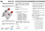
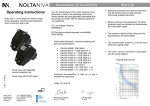
Declaration of conformity Operating instructions Nolta motor starter for electric-motor driven apparatuses, machines and equipment that can be moved from site to site. We, the manufacturer which is described instructions, hereby complies with the guidelines. of the motor protection plug, in detail in the operating declare that this product following standards and EC Low Voltage Directive 2006/95/EG EC Directive on Electromagnetic Compatibility 2004/108/EG Start up Electrical connection and fault repairs must be only carried out by a qualified electrician. Before working on the equipment, the motor protection plug must always be disconnected from the power supply. The motor must be connected in accordance with the wiring diagram. Harmonised standards, national standards and technical specifications: 11 8012 / 10.2013 Power plugs with integrated motor protection switch and temperaturecompensated thermal trips. CEE plugs 16A and 32A, optionally with or without phase-sequence indication and phase inverter. Nolta GmbH Industriestrasse 8 35091 Coelbe Germany Tel. +49(0)6421/98590 Fax +49(0)6421/985928 www.nolta.de [email protected] DIN EN 60999 / VDE 0609-1 DIN EN 55014-1 / VDE 0875-14-1 DIN EN 60947-4-1 / VDE 0660-102 DIN EN 60947-3 / VDE 0660-107 DIN EN 61000-6-1 / VDE 0839-6-1 DIN EN 61000-6-2 / VDE 0839-6-2 DIN EN 61000-6-3 / VDE 0839-6-3 DIN EN 61000-6-4 / VDE 0839-6-4 DIN EN 60529 / VDE 0470-1 DIN EN 60695-1-10 / VDE 0471-1-10 DIN EN 60695-1-11 / VDE 0471-1-11 Technical documentation is held by us and is available for inspection. Old equipment can be returned for disposal to NOLTA in Coelbe, Germany. Other NOLTA- Motor Starters: NOLTA-rotary toggle starter with thermal- electromagnetic release and phase inverter + phase sequence indicator. NOLTA- Motor Starter with contactor and motor protective relay that has a thermal release and phase inverter + a phase sequence indicator as well as an operation indicator. 28.10.2013 NOLTA-push button starter with thermal- electromagnetic release and phase inverter + phase sequence indicator. Managing Director Dr.-Ing. J. Knake QA Manager W. Seip Operation Wiring diagram rotary toggle right (0) rotary toggle left () The data in brackets is for a power reversing switch. Power plug with On/Off switch Rotary toggle for switching On/Off: Off On Technical data Phase inverter and Phase sequence indicator (optional) L1 L2 L3 N PE Rotary toggle for reverse switching (see picture below) Off On On rotary toggle middle (0) rotary toggle right () Motor turns right rotary toggle left () Motor turns left 2 1 For the integrated phase sequence indicator and phase inverter: Red light = wrong phase sequence 4 3 6 5 1 3 5 U V W 3-Phase-Motor W The direction of rotation is changed by lightly pressing and turning the pole pins in the socket. N PE Power reversing Plug Phase inverter and Phase sequence indicator (optional) L1 10 L2 6 L3 N PE Rotary toggle right: Motor turns right 9 7 9 7 Nominal operating voltage: see type print * Nominal operating current: 32 A max. (20 A) Perm. power frequency: 50…60 Hz Temperature range: - 25...+ 50 °C Max. back-up fuse rating: 32A (25 A) Housing: Polycarbonate Degree of protection: IP44 Cabel entry: PG21 Clamping range: 11…21 mm Number x Cross-sectional area: single core 4,0 mm² (2,5mm²) fine stranded 2,5 mm² * nominal voltage is established by the plug attachment and the phasesequence unit. 5 Switch left T1: 9 T2: 7 T3: 5 Switch right T1: 9 T2: 5 T3: 7 1x10 switching cycles 2 1-0-1 Rotary toggle left: Motor turns left 5 Mechanical service life: 5 3-Phase-Motor N PE