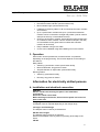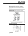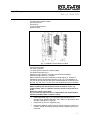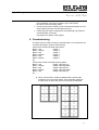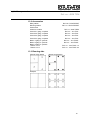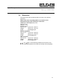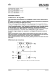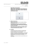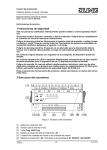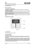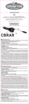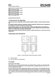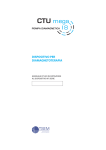
1
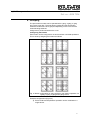
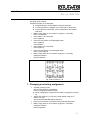
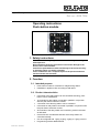
Light Management Push-button module Ref.-no.: 4008 TSM Operating instructions Push-button module 1. Safety instructions Electrical devices may only be installed and fitted by electrically skilled persons. Non-compliance with the instructions could cause damage to the device, fire or other hazards. Connect the push-button module exclusively to the universal relayor dimming station (no mains potential!). These instructions are a component part of the product and must remain with the end customer. 2. Function 2.1. Intended purpose Push-button module for connetion to relay/dimming station. Installation in appliance box according to DIN 49073 2.2. Product characteristics Stand: Okt-12 325 270 03 8 channels of the relay station can be controlled: switching, pushbutton control, blind/shutter 16 channels for relay station connected in parallel in conjunction with the push-button extension module 4 channels of the dimming station can be controlled 8 channels for relay station connected in parallel in conjunction with the push-button extension module All channels of the relay station are in switching mode in the state as delivered. Central function: all selected channels of the relay station are controlled centrally. Can be configured with 1-gang, 2-gang, 3-gang or 4-gang cover kit Programming without additional aids. Light Management Push-button module Ref.-no.: 4008 TSM Free assignment of the groups to the channels. Red LED as status indicator (can be switched off). Blue orientation light (can be switched off). Feedback of switching states on all connected push-button modules and modules. Up to 4 push-button modules with up to 4 push-button extension modules can be connected to a single relay station (can be used for example in two-way or intermediate circuits). Cloning of push-button modules: transmitting the button assignment of a module to other modules. Can be used for example in two-way or intermediate circuits (push-button modules with extension module can be cloned) Easy installation using 2-wire cable Covers can be labelled using laser labelling tool on the Internet 3. Operation Each button can be operated over its entire surface or top/bottom, depending on the programming. The function depends on the setting of the stations. Relay station: Switching / push-button control: press button briefly. Move blind/shutter: long press on button. Stop blind/shutter or adjust slats: press button briefly. Dimming station: Switching: press button briefly. Dimming: long press on button. Information for electrically skilled persons 4. Installation and electrical connection DANGER! Electric shock from touching live parts in the installation environment. An electric shock can be fatal. Before working on the device, disconnect the power and cover live parts in the area. Snapping on the adapter frame An adapter frame is required depending on the design range LS ranges and Flat Design The adapter frame LS4AR is pre-assembled. AS 500 and A ranges The adapter frame LS4AR is not required. Dismount the adapter frame by means of pressing at the edge of the frame. CD 500 2 Light Management Push-button module Ref.-no.: 4008 TSM The adapter frame LS4AR is not required. Dismount the adapter frame by means of pressing at the edge of the frame. Assemble the adapter frame CD4AR. Snap adapter frame CD4AR in the right orientation from the front onto the module (4) (Figure 2).Observe the label “TOP”. Connection Caution! Connect the push-button module exclusively to the universal relay/dimming station. Fig. 1: Connection of push-button module (TSM) and push-button extension module (TSEM) to the universal relay station Installing and connecting the device Fig. 2: Installation (1) Supporting ring (2) Frame 3 Light Management Push-button module Ref.-no.: 4008 TSM (3) Adapter frame (4) Push-button module (TSM) (5) Locking screw (6) Cover kit (7) Connecting terminal (8) Box screws Fig. 3: Installation with extension module (9) Connecting cable (10) Plug-in position (11) Push-button extension module (TSEM) (13) Double supporting ring Supporting ring A side for: A ranges, CD 500 and Flat Design. Supporting ring B side for: LS ranges. When using the push-button extension module (Figure 3): Preferred installation vertical. Use double supporting ring (13). For installation on only one flush-mounted box the lower screws should be countersunk into the wall, e.g. with a ø 6 x 10 mm hole. Use supporting ring as a template. DANGER! When installing with 230 V devices under a common cover, e.g. socket outlets, there is a danger of electric shock in the event of an error! An electric shock can be fatal. Do not install any 230 V devices in combination with a push-button extension module under a common cover! Install supporting ring (1) or (13) in the right orientation on an appliance box. Observe the label "TOP"; label A or B forwards. Use only the supplied box screws (8). Plug frame (2) onto the supporting ring. Preferred installation position of push-button extension module (11) is below. Guide connecting cable (9) between supporting ring and frame bar. 4 Light Management Push-button module Ref.-no.: 4008 TSM Push-button extension module: insert connecting cable (9) in the right orientation in the plug-in position (10) in the module. Do not pinch the connecting cable. Connect push-button module (4) with connecting terminal (7) to the relay station and insert onto the supporting ring. Fasten the push-button module(s) to the supporting ring using the enclosed plastic screws (5). Only tighten the plastic screws lightly. 5. Commissioning The push-button module is ready for operation after it is connected to the universal relay station (initial commissioning). Push-button module Universal relay station Button 1 top Output 1 Button 1 bottom Output 2 Button 2 top Output 3 Button 2 bottom Output 4 Button 3 top Output 5 Button 3 bottom Output 6 etc... Push-button module Universal dimming station Button 1 top Output 1 dimming up Button 1 bottom Output 2 dimming down Button 2 top Output 3 dimming up Button 2 bottom Output 4 dimming down Button 3 top Output 5 dimming up etc... When a push-button module is operated with a push-button extension on a single relay station, the push-button extension module does not have any function in the state as delivered. 5 Light Management Push-button module Ref.-no.: 4008 TSM Fig. 4: Button assignment in state as delivered without and with pushbutton extension module. 6 Light Management Push-button module Ref.-no.: 4008 TSM 6. Grouping The push-button module can be operated with 1-gang, 2-gang, 3-gang and 4-gang cover kits. The push-button module and the push-button extension module have to be grouped depending on the cover and the channels being switched. Assignment is performed without the cover. Configuring the buttons Each button can be configured for its entire surface or divided top/bottom. This is done by assigning the buttons as follows. Fig. 5: Button configuration for entire surface or top/ bottom operation, for 1-gang, 2-gang, 3-gang and 4-gang covers. Example configurations (Figure 5). Entire-surface and top/bottom operation can be combined on a single device. 7 Light Management Push-button module Ref.-no.: 4008 TSM 1-gang button Configure for entire surface: Press micro button 1 and then 16. Configure top/bottom: Upper half: press micro button 1 and then 4 Lower half: press micro button 13 and then 16 2-gang button Configure left-hand button for entire surface: Press micro button 1 and then 14. Configure right-hand button for entire surface: Press micro button 3 and then 16. Configure top/bottom: Left-hand button Upper half: press micro button 1 and then 2 Lower half: press micro button 13 and then 14 etc. Activating the grouping mode The grouping mode is activated on the push-button module. No switching commands are executed in the grouping mode. Cover is not installed. Press micro buttons 6 – 3 – 5 – 5 in sequence. All LEDs flash 2 x Press micro buttons 6 – 3 – 5 – 5 in sequence once again. All LEDs flash 2 x LEDs 1 to 8 (16) flash, the grouping mode is active. Normal operation after 2 minutes without any button being pressed. Assignment of the buttons to the outputs of the relay station Grouping mode is active. LEDs of free channels flash. LEDs of assigned channels light up continuously A unit comprising a TSM and a TSEM is commissioned via the TSM. Assigned buttons are overwritten if they are assigned again. Select channels 1-8 (16) of the relay station using micro buttons 1-8 (16). The LED of the selected channel lights up. All other LEDs are OFF. Press 2 micro buttons of the assigned button (Figure 5). LEDs of free channels flash. LEDs of assigned channels are ON Repeat the assignment until all desired channels have been assigned. Continue with central function or end assignment. Make a long press on micro button 16 (approx. 3 seconds). Assignment ended. Normal operation 8 Light Management Push-button module Ref.-no.: 4008 TSM Central function Grouping mode is active. At least one button is not assigned. Assigned buttons are overwritten if they are assigned. It is also possible to configure only central ON or central OFF. Central ON and central OFF can be configured in any desired sequence. Make a long press on micro button 15 (approx. 3 seconds) LEDs 1 and 2 flash Press button 1 for central On LED 1 lights up Press 2 micro buttons of the assigned button LED 1 lights up LED 2 flashes Press button 2 for central Off LED 2 lights up Press 2 micro buttons of the assigned button LEDs 1 and 2 light up Make a long press on micro button 16 (approx. 3 seconds) Assignment ended Normal operation Fig. 6: Micro buttons 1-16 7. Changing an existing assignment Activate grouping mode LEDs of free channels are flashing. LEDs of assigned channels are ON When changing the central function make a long press on button 15. Select new channels 1-8 (16) of the relay station using micro buttons 1-8 (16). The LED of the selected channel lights up Press 2 micro buttons of the button being changed (Figure 5) Make a long press on micro button 16 (approx. 3 seconds) Assignment ended. Normal operation 9 Light Management Push-button module Ref.-no.: 4008 TSM 8. Status LED switching on or off The push-button module is in normal operation Cover kit is configured. Make a long press on button at top or button in a line with the LED for approx 10 seconds Red status LED next to the button is switched on or off. 9. Operation LED switching on or off The push-button module is in normal operation (i.e. not in programming mode). The cover kit is not assembled. 10. Press push-button module at the 4 corners for approx. 10 seconds (4 micro buttons at the corners, 1-4-13-16, are pressed simultaneously). Blue operation LED is switched on or off. The push-button extension module does not have any operation LED. Reset Reset push-button module to the state as delivered. All settings are overwritten. The push-button module is in normal operation. Press micro buttons 12 – 9 – 7 – 9 in sequence. All LEDs flash 2 x Press micro buttons 12 – 9 – 7 – 9 in sequence once again. All LEDs flash 2 x. The state as delivered has been restored. Push-button module is ready for operation. 11. Installing cover kit The buttons are available as a complete cover kit. Individual buttons or the complete cover kit can be replaced using buttons with symbols. The assembling web is not necessary to install the buttons. Place buttons on the device in the right orientation and push briefl y to snap in. Observe the label "TOP". Laser-print buttons at www.jung-label.de 10 Light Management Push-button module Ref.-no.: 4008 TSM 12. Cloning push-button modules "Cloning" means transmitting the button assignment of a push-button module to other push-button modules. No operation of the relay station is possible during an ongoing cloning operation. Only pushbutton modules can be cloned from each other. Several push-button modules are connected to the relay station. Press MODE and Central Switching Mode buttons simultaneously until the LEDs c, ON/n and OFF/o flash. The relay station and push-button modules are in cloning mode. The red LEDs on the push-button modules are flashing. Press a button on the push-button module being cloned within approx. 2 minutes. The red LEDs on the push-button module are flashing rapidly. The red LEDs of the other the push-button modules continue to flash. Press a button on another push-button module within approx. 2 minutes. All of the red LEDs on both push-button modules flash rapidly. The button assignment has been applied to the push-button module, and cloning mode is terminated. 13. For further push-button modules, repeat the steps described above. Cloning mode cannot be stopped manually. In order to abort a cloning mode process, do not actuate any push-button module for 2 minutes. If cloning mode was activated at the relay station without any connected push-button modules, cloning mode is terminated automatically after 2 minutes. Appendix 13.1.Technical data Power supply via universal relay/dimming station Min. current TSM Max. current TSM Min. current TSM + TSEM Max. current TSM + TSEM Protection level Safety class Ambient temperature Storage temperature Connection type Cable length Cable type DC 24 V approx. 3 mA approx. 12 mA approx. 3 mA approx. 19 mA IP 20 III +5 ... +45 °C -25 ... +70 °C connection terminal max. 100 m J-Y(St)4 2x2x0.8 11 Light Management Push-button module Ref.-no.: 4008 TSM 13.2.Accessories Relay station Dimming station Push-button extension module Cover kit 1-gang, complete Cover kit 2-gang, complete Cover kit 3-gang, complete Cover kit 4-gang, complete Button 1-gang w. symbols Button 2-gang w. symbols Button 4-gang w. symbols f. button 1 or 4 f. button 2 or 3 Ref.-No.: RS 8 REGHE Ref.-no.: UDS 4 REGHE Ref.-no.: 4094 TSEM Ref. no.: ..401 TSA.. Ref. no.: ..402 TSA.. Ref. no.: ..403 TSA.. Ref. no.: ..404 TSA.. Ref. no.: ..401 TSAP.. Ref. no.: ..402 TSAP.. Ref. no.: ..404 TSAP..14 Ref. no.: ..404 TSAP..23 13.3.Planning aids Channel relay station Button programming Example 12 Light Management Push-button module Ref.-no.: 4008 TSM 14. Guarantee Our products are under guarantee within the scope of the statutory provisions. Please return the unit postage paid to our central service department giving a brief description of the fault: ALBRECHT JUNG GMBH & CO. KG Service-Center Kupferstr. 17-19 D-44532 Lünen Service-Line: +(49) 23 55 . 80 65 51 Telefax: +(49) 23 55 . 80 61 65 E-Mail: [email protected] General equipment Service-Line: +(49) 23 55 . 80 65 55 Telefax: +(49) 23 55 . 80 62 55 E-Mail: [email protected] KNX equipment Service-Line: +(49) 23 55 . 80 65 56 Telefax: +(49) 23 55 . 80 62 55 E-Mail: [email protected] The -Sign is a free trade sign addressed exclusively to the authorities and does not include any warranty of any properties. 13