1
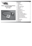
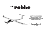
Contents Page
1.
2.
3.
Installation and operating instructions
for
Gyro GY520
No. F 1244
4.
5.
5.1
6.
7.
7.1
7.2
7.3
7.4
7.5
7.6
8.
9.
10.
11.
12.
13.
14.
15.
16.
17.
18.
19.
General
Contents
Technical Data
• Features, Functions
Installation
Connection (Standard, parallel)
Connection (S-BUS, serial)
Setting up
Programming Menu
Servo Mode (selection)
Gyro normal/reverse rotation
Limit Setting (Tail rotor throw)
Flight Mode (F3C / 3D)
Response Selection
Data Reset to factory default
LED-indicator and Gyro Status explanation
Adjust and save the neutral position
Adjust the gyro sensitivity
Tail rotor servo linkage
Check of servo direction
Check of the gyro sense
Operation of the GY520 in AVCS-Mode
Accessories
After life disposal
Declaration of Conformity
Guarantee
Service addresses
2
2
2
3
3
3
4
4
4
4
5
5
5
5
6
6
6
6
7
8
8
9
10
11
11
11
12
2. Contents
You have chosen a precision system with the GY520 gyro.
Although the operation of this gyro is easy, the programming does require a basic knowledge by the user. The instructions are written to
help you become confident in its use.
Therefore, the instructions must be read and understood before installation and use of the Gyro.
1. General
The GY520 gyro is a particularly small and light high performance gyro
suitable for all types and classes of helicopters. It is suitable for both,
electro, as well as internal combustion (IC) powered helicopters.
Due to the use of highly integrated MEMS, (Micro Electric Mechanical
System) –Technology, the sensor element and the digital control electronics can all be housed in a compact case.
Fitted with a novel, wear free MEMS-semiconductor-sensor; the gyro
has a “soft” feel on the tail rotor, and at the same time having a solid
“lock” when needed. The gyro may be operated in normal or in AVCS
modes (Active Angular Velocity Control System), which is similar to a
Heading - Hold (Lock)-System.
•
•
•
•
•
•
•
Note:
In AVCS mode, the pitch to tail mixing (Revo-Mix) is not operable. This
is also not absolutely necessary in Normal Mode either.
3. Technical Data GY520 Gyro:
When the model is disturbed, e.g. side-wind, and in normal mode, the
gyro will only try to give a control signal correction only as long as the
tail rotor servo is trying to move the tail of the helicopter. As soon as
the tail movement has stopped, then the gyro stops trying to correct
any unwanted movement of the helicopter.
In AVCS-mode, the gyro will continue to correct the tail position (with
a control signal to the servo), until the helicopter returns to its original
position.
© robbe Modellsport
1 GY520 gyro
1 350 mm red connecting lead
1 350 mm black connecting lead
2 Double-sided adhesive foam pads 2 mm
2 Double-sided adhesive pads 3 mm
1 Metal plate damper
1 Mini screwdrivers
2
Operating voltage:
Temperature range:
Weight:
Current draw:
Dimensions:
Control frequency:
Sensor rate range:
4,8 - 6 Volt at receiver output
-15 °C to +45 °C
6.9g or 10 g including connectors
40 mA (without servo)
20,7 x 20,7 x 10,4 mm
1520 μs = 280 Hz, 760 μs = 560 Hz
800°/second
E-Heli
Features:
• Particularly fast reaction due to the High-Speed Microprocessor
and the pure digital signal processing and control is faster than the
GY401.
• Soft control feel but still having a “hard-lock“.
• Symmetrical rotational rate for left and right
• Detects the smallest angular speed changes.
• “Antistatic-Case material“ protects against electrostatic discharges and interference.
• Very small and light due to use of SMD-Technology
Foam pad
Damper plate
Foam pad
Monitor-LED
Functions
• Step less gyro gain adjustment from transmitter (Tx)
• Switchable between Normal- and AVCS Modes from Tx
• Adjustable gain
• Adjustable to suit maximum left and right tail rotor servo throw
(Limit).
• Selection of Digital-or Analogue servos
• Selection for Flight style F3C (soft) and 3D (hard)
• Selection of servo neutral position 1520 / 760 μs
• LED Monitor to display the current gyro status.
• Programming with a single button on gyro
• Software to program on PC (USB-Adapter required)
• Integrated S-BUS System
Chassis
Push button
Auxiliary channel = gyro gain
Connection
Tail rotor servo
4. Installation
Attach the supplied foam pads to the gyro case and mount on a vibration-free part of the helicopter chassis. Mount it so that the gyro
base is at right angles (90°) to main rotor shaft.
For helicopters with high levels of vibration and IC powered models,
the metal damper plate should be mounted on the model with a double-sided foam pad and the gyro mounted to this plate with an additional foam pad.
© robbe Modellsport
IC-Heli
Gyro
3
To Receiver output
Auxiliary channel (Red)
Tail rotor
Tail rotor channel
(Black)
5. Connection (Standard - parallel)
A vibration damped mounting is extremely important, because the
MEMS-Sensor will detect the smallest of movement. For electro-helis,
we recommend using just the 2 mm Foam-Pads, for IC helis, use 2 of
the 3 mm pads plus the damper plate. Take care during the assembly
and connection that the gyro case does not touch any other part of the
helicopter. The cables must not be under tension or the damping of the
gyro will be affected. Take care that the cables cannot transfer any vibration from the Helicopter - Chassis to the gyro.
Secure the cables also.
7. Programming Menu
The important programming adjustments can be made directly on the
gyro without having to connect the gyro to a PC. By using the side
mounted “Push“ button and the LED-monitor, the following programming adjustments can be made.
Firstly power up the gyro as described above.
5.1 Connection (S-BUS - serial)
Later and when receivers are available with a serial S-BUS output, it
will possible to connect only the S-BUS lead to the gyro socket “R“.
The lead to the auxiliary channel will no longer be necessary. The tail
rotor servo will continue to be plugged into the “S“ socket on gyro.
Factory standard settings of the gyro*
Servo-Mode:
-> Digital servo, neutral 1520 μs
Gyro-reverse:
-> Normal
Limit-adjustment:
-> 420 μs (100%)
Flight-Mode:
-> F3C
Reaction adjustment:
-> Standard
Activate the programming menu:
Press “Push“ button for 3 seconds
7.1 Servo Mode
The gyro witches to program mode, and the flash sequence 1 begins
to show and allow programming of the Servo Mode.
LED Status
Single blue flash
Single red flash
Single purple flash
6. Operation
The use may begin as soon as a digital servo with neutral point of 1520
μs is available.
Tip: In this mode, do not use an analogue servo, due to the high frequency; it can damage the servo beyond repair. To connect an analogue servo, first change the servo-mode to Analogue and then you can
connect a servo.
•
•
•
•
•
•
Servo recommendations:
Digital servo 1520 μs = S 9254, S 9257, S 9253, BLS 254, BLS 257
Digital servo 760 μs = S 9256, S 9251, BLS 251
Switch on Tx
Switch on Rx
The gyro start sequence begins
Tip: If the LED slowly flashes red, there is no Rx input signal
Warm up -> LED flashes slowly blue
Sensor alignment -> LED flashes blue quickly
During the sensor alignment, do not move the model/gyro for 3-5
seconds!
After alignment: LED flashes red = AVCS-Mode
LED blue = Normal Mode
The tail rotor moved 4 times left and right, to signal that the gyro
function is now active.
© robbe Modellsport
Program
Digital servo Neutral 1520 μs *
Digital servo Neutral 760 μs
Analogue servo
4
When pressing the “Push” button, the LED will flash rapidly, during
this time, the program
Selection can be made with repeated pressing of the “Push“ button.
When programming is completed, the LED will switch to a slow flashing sequence to indicate Display Mode. If the settings are changed,
then the colour of the LED will also change. If you need to make further changes to the settings, then the LED colour will also change, then
activate the fast flashing mode by pressing „Push“ and make any adjustments by using the „Push“ button during the fast flashing stage.
Paging step-by step through the various pre-programmed factory settings will make selection of settings. (Digital 1520-> Digital 760->Analog -> Digital 1520 etc.)
To reverse gyro sense, press “Push“ – button for 3 seconds.
If The LED lights blue, then the settings are above 50%, correct and
will be stored. To make Flight Mode selection, press. “Push“ – button
for a further 3 seconds.
7.2 Gyro normal/reverse rotation
As previously described, activate the short flashing sequence and
switch to programming mode.
LED Status
2 x blue flashes
2 x red flashes
Setting
Normal*
Reverse
7.4 Flight-Mode
Activate the rapid flash sequence by pressing, “Push” and switch to
settings.
LED Status
Setting
4 x blue flashes
F3C - Mode*
4 x red flashes
3D / F3N Mode
In F3C Mode, the gyro has a very precise control of the tail rotor and
in 3D-Mode; the priority is to have a quick reaction to the control input
made by the tail stick signal. To switch to the control response settings, Press “Push“ – button for 3 seconds.
To access the Limit-Setting, press the “Push“ button for a further 3
seconds.
7.3 Limit-Setting
To avoid damage to the servo if it hits its mechanical limit, release the
tail rotor control linkage before programming the servo throw limits.
Limit adjust is a separate adjustment of the maximum right and left
servo travel. The tail rotor travel is increased by the gyro and is 150%
of the “normal“ servo travel.
7.5 Response-Settings
This menu will adjust the gyro Response-settings.
We recommend the use of “Standard” or “Slow” mode settings for 3D
and small electro-helis. For larger and heavy scale models, the “Fast”
mode setting is recommended. Try all settings in flight to see which
one best suits your flying style and the model
Activate the rapid flashing by quickly pressing the “Push“ button, select the left travel by moving the tail stick on the Tx to the left, and
press “Push“. Thereafter, move the stick to the right and press “Push“
again.
The LED switches to a triple flash sequence.
Activate the rapid flash sequence on the LED by pressing, “Push” to
switch to settings.
After setting the approximate servo travel, re-connect the linkage to
make the fine adjustments to servo travel. Press “Push“ again and adjust the exact travels for left and right (or reversed).
LED Status
5 x blue flashes
5 x red flashes
5 x purple flashes
Tip:
The servo travel limit settings must be at least 50% each side, otherwise, settings less than 50% will not be stored, and this is to ensure
that sufficient servo travel is available to effectively maintain control
of the model. If the LED shows red, then the limit value is set lower
than 50% and will not be stored.
© robbe Modellsport
Setting
Standard*
Fast
Slow
To switch to “Data Reset to factory defaults”, press “Push“ – button for
3 seconds.
5
7.6 Data Reset to factory default settings
9. Adjust and store the neutral point
Activate rapid flashing by pressing “Push” and when flashing, press
”Push” 3 x times. The LED flashes “purple” to indicate that the data
has been reset to factory default settings.
The gyro needs to store the tail rotor servo neutral point. Leave the Tx
stick in the neutral position.
Then switch the Tx and Rx on. The servo neutral will be automatically
stored during the switch on sequence. Each time the radio is switched
on, then the Tx stick and trim must be left in the neutral position. The
neutral position of the servo will always be correctly stored according
to the stick and trim positions during switch-on sequence.
The Default Settings are:
Servo-Mode:
-> Digital servo, Neutral 1520 μs
Gyro rotation:
-> Normal
Limit-Setting:
-> 420 μs (100%)
Flight-Mode:
-> F3C
Response-Setting:
-> Standard
10. Setting the Gyro gain
To exit the programming menus, switch the power off to the Rx and
gyro.
The gyro gain may be adjusted proportionally between 0-100% from
the Tx. At 0% gyro gain, the gyro stabilisation is turned off. So that
you are able to use the maximum gain, check that the servo does not
hit the mechanical limits (see Limit Settings).
8. LED-indicator and Gyro Status
Function
Status
LED Monitor
Start
Warm-up
flashes slowly blue
Start
Start
Operation
Operation
Operation
Operation
AVCS Mode
Initialisation
Sensor alignment
Normal mode (dormant)
AVCS-mode (dormant)
Right hand rotation
Left hand rotation
Offset tail neutral point
© robbe Modellsport
flashes slowly red
When using a robbe/Futaba Tx, the gyro gain uses channel 5. This
channel should be a proportional control with a slider or rotary potentiometer. You then have the possibility to adjust the gyro mode and
gain in flight to suit flight and a weather conditions.
flashed quickly blue
The Tx control to gyro gain relationship is illustrated in the following
diagram.
blue light
red light
The control travel is split into two areas. From the middle to the top,
the gyro works in AVCS-Mode, between 0- 100%. In the middle, with
the gain set to o%, the gyro is turned off.
flashes quickly blue
flashes quickly red
flashes slowly purple
6
....Gyro gain
Tx Control
Mode
Off
From the mid point to below, the
gyro works in Normal-Mode, from
0-100%.
Following this method, and using
a linear control, you are able to
switch gyro mode and also adjust
the gain fully proportionally.
Here is an example of the settings required for the tail rotor gain.
The menus vary according to the Tx, so please see the individual radio
instructions to be able to adjust your own Tx.
A pulse value of 500 μs sets the
gain to 100% = ATV/AFR 100%
Recommendations for gyro gain
The correct gyro gain is dependent upon the helicopter model and the
servo used. Basically, the higher the quality and speed of the servo, the
higher the in flight gain can be set.
Naturally, a switch can be used as an alternative to the linear potentiometer, but this will only allow switching between modes. The gain
will have to be set by using percentage values in channel 5 ATV or AFR
- Menus.
Recommended settings:
With rotor diameter larger than 120 cm Hover 70-100 %,
Circuit flying 30-60%, for smaller helis- use lower values. The optimum setting is to use a percentage gain set just before tail-wagging
starts.
The Tx flight phase programs may also be used to switch different settings on and off. The FutabaT14MZ, T12FG, T12Z, FX-40 and FX-30
systems are set as standard without the gyro channel active.
These radio have a special gyro setting menu, which has the mode as
well as gain pre-set and to be switched on or off by a separate switch
or flight phase.
11. Tail rotor servo linkage
If you require the gyro gain to be adjusted by a linear slider, then gyro
1 or 2 must be selected in the function menu. It should be noted that
the settings in the menu and control inputs on the slider could work
against each other.
© robbe Modellsport
7
After turning on the radio, ensure
that the servo arm is at 90°/ right angles to the servo case. Choose a
servo arm around 15 - 18 mm long
and check linkage for no binding,
slop-free and light operation.
Gyro rotation
12. Check servo rotation
When moving the Tx tail rotor stick to the left, then check that the tail
rotor works according to the sketch. If it works in the opposite control
sense, then the direction of the servo must be reversed in the Tx
Servo-Reverse menu.
Clockwise rotor system
anti clockwise rotor system
anti clockwise rotor system
Check the gyro rotation before each take-off
Clockwise rotor system
anti clockwise rotor system
Tip:
Set tail rotor throws to maximum.
Take care that correct base set-up of the tail rotor pushrod is made
first and then set the throws. Move the tail rotor Tx stick to left and
right and set the trim for maximum throw in each direction (Limit - Setting) such that the servo and tail rotor linkages do not reach the mechanical end stops.
anti clockwise rotor system
13. Check gyro rotation
To be able to check the correct “sense” of the GY520, it needs to be
working like a conventional gyro. Therefore, ‘Normal-Mode’ must be
turned on in the Tx.
During flight, this will prevent overloading and damaging the servo during flight.
Lift the helicopter up by hand and rotate it quickly to left, the gyro
should now control the tail rotor blades as in the sketch. If it works in
the opposite direction, then the gyro rotation direction must be re versed in the “Gyro-Rotation” menu
© robbe Modellsport
8
Start the Motor, hover and fly in AVCS-Mode and adjust the gain according to the above-described methods. Check in AVCS-Mode that
the gain is set lower than in Normal-Mode.
14. Operating the GY520 in AVCS-Mode
After setting the Normal-Mode, you may now set-up the gyro for
AVCS-operation. Set the tail rotor trim to the same value as that used
in the Normal-Mode.
Note:
We would like to point out that the automatic that the automatic storage of the neutral point in AVCS-Modus, (3 x movement of the auxiliary channel within one second), can sometimes lead, in unfavourable
interference conditions, can lead to an incorrect setting. The resulting
wrong setting of the tail rotor neutral point can lead to a poor or uncontrollable control of the tail rotor.
To ensure that the Neutral position is identical in Normal and AVCS
Modes, one can automatically set the AVCS neutral to the same setting as that used for the Normal-Mode.
Use the following procedure:
Set the tail rotor stick to the neutral position in Normal Mode, slide the
Tx linear slider control (channel 5, gyro sensitivity) 3 x back and forth
between maximum and minimum throws (Normal- and AVCS-Modes)
within one second to set the gyro to AVCS-Mode.
We therefore recommend that you only use a PCM or 2,4 GHz Rx to
avoid this effect.
Should a PPM (FM) - System nevertheless be used, it is very important to ensure that the system has an excellent range.
This method will store the AVCS-Mode neutral position. The monitor
will make a rhythmic single flash. This position will be stored when
switching on again.
This particularly important when in flight, where some manoevres,
which cause a dramatic change in the aerial position, such as the stall
turn, which will highlight a poorly aligned (particularly when mixers are
in operation) RC – System’s range limit.
A corrupt radio signal can, under these extreme conditions, lead to a
command being interpreted by the gyro to move the servo neutral
point.
Special case:
To be able to lift-off in AVCS-Mode in the neutral position and also to
recall the set value, move the tail rotor stick from left to right 3 x within 1 second. The servo will then move to its programmed neutral position.
Check whether all Tx settings (Idle up, flight phase switch etc.) are correctly programmed and stored by the LED display.
Should the LED flash slowly purple, then the tail rotor trim position
has been moved for this flight phase.
Return the trim lever to its correct position.
© robbe Modellsport
9
For Windows Vista/XP/2000 operating systems.
15. Accessories
Rx connector lead GY520
The Rx connector lead for the GY520 has a double male plug. This
has the advantage that, when using the gyro in different size helicopters, the correct length of lead can be selected for the installation.
Following leads are available as accessories:
No. 4090 Connector lead GY520 red and black 65 mm
No. 4091 Connector lead GY520 red and black 90 mm
No. 4092 Connector lead GY520 red and black 140 mm
No. 4093 Connector lead GY520 red and black 215 mm
Software for GY520 gyro
Software for GY520 gyro may be found in the Download area of the
robbe-Service-Center on the robbe Homepage. The software allows
easy configuration and programming of the gyro to be made.
http://www.robbe.com/rsc/html/downloads.htm
The programming and settings for different models can be stored as
separatedata files on your PC.
USB-Adapter CIU-2 No. F 1405
Adapter to adjust Servo, Speed Control and Gyro parameters with PCSoftware.
© robbe Modellsport
10
For this, then the USB-Adapter No. F 1405 is necessary. Suitable
drivers for Windows Vista/XP/2000 operating systems area also available to download on the robbe website.
18. Guarantee
16. After life disposal
Naturally we guarantee this gyro for the statuary period of 24 months.
If you believe you have a valid claim under guarantee, please contact
your dealer in the first instance, as he is responsible for processing
guarantee claims.
During this period we will correct any operating faults, production defects and material faults which arise, at no charge to you. We will not
entertain any claims beyond these terms, e.g. consequent damage.
Goods must be sent to us carriage-paid; we will pay return carriage.
Goods sent without pre-paid carriage will not be accepted.
This symbol means that you must dispose of electrical and
electronic equipment separately from the general household
waste when it reaches the end of its useful life.
Take your equipment to your local waste collection point or
recycling centre. This applies to all countries of the European Union,
and to other European countries with a separate waste collection system.
We accept no liability for transit damage and the loss of your shipment; we therefore recommend that you take out suitable insurance to
cover these risks. Send the unit to the Service Centre responsible for
your country.
17. Declaration of Conformity
robbe Modellsport GmbH & Co. KG hereby declares that this product
satisfies the fundamental requirements and other relevant regulations
contained in the appropriate CE directives. The original Conformity
Declaration can be viewed on the Internet under www.robbe.com: click
on the logo button marked “Conform” which is included in each device
description.
The following conditions must be fulfilled if we are to process your
guarantee claim:
• Send proof of purchase (till receipt) with your shipment.
• The unit must have been used in accordance with the operating
instructions.
• The unit must have been operated with the recommended power
sources and genuine robbe accessories.
• The unit must not exhibit damage due to damp, unauthorised intervention, excessive voltage, overload conditions or mechanical
stress.
• Please include a concise, accurate description of the fault or defect, as this helps us locate the problem quickly.
robbe Modellsport GmbH & Co. KG
Metzloser Strasse 38
D-36355 Grebenhain
Telefon ++49-6644-870
www.robbe.com
Copyright 2009
© robbe Modellsport
11
19. Service Centre Addresses
Country
Company
Street
Town
Telephone
Fax
E-Mail
00376-862 865
00376-825 476
[email protected]
0045-86-43 77 44
[email protected]
Andorra
Sorteney
Santa Anna, 13
AND-00130 Les escaldesPrincip. D'Andorre
Denmark
Nordic Hobby A/S
Bogensevej 13
DK-8940 Randers SV
0045-86-43 61 00
Germany
robbe-Service
Metzloser Str. 36
D-36355 Grebenhain
0049-6644-87-777 0049-6644-87-779 [email protected]
England
robbe-Schlüter UK
LE10-UB
GB-LE10 3DS Leicestershire
0044-1455-637151 0044-1455-635151 [email protected]
France
S.A.V Messe
6, Rue Usson du Poitou, BP 12 F-57730 Folschviller
Greece
TAG Models Hellas
18,Vriullon Str.
GR-14341 New Philadelfia/Athen 0030-2-102584380 0030-2-102533533 [email protected]
Italy
MC-Electronic
Via del Progresso, 25
I-36010 Cavazzale
di Monticello C.Otto (Vi)
0039 0444 945992 0039 0444 945991 [email protected]
Netherl. / Belgium
Jan van Mouwerik
Slot de Houvelaan 30
NL-3155 Maasland
0031-10-59 13 594 0031-10-59 13 594 [email protected]
Norway
Norwegian Modellers Box 2140
N-3103 Toensberg
0047-333 78 000
0047-333 78 001
[email protected]
Austria
robbe-Service
A-1220 Wien
0043-1259-66-52
0043-1258-11-79
[email protected]
Sweden
Minicars Hobby A.B. Bergsbrunnagatan 18
S-75323 Uppsala
0046-186 06 571
0046-186 06 579
[email protected]
Switzerland
Servicecenter Hässig Baslerstrasse 67 a
CH-4203 Grellingen
0041-61-741 23 22 0041-61 741 23 34 [email protected]
Slovak Rep.
Ivo Marhoun
Horova 9
CZ-35201 AS
00420 351 120 162
Spain
robbe-Service
Metzloser Str. 36
D-36355 Grebenhain
0049-6644-87-777 0049-6644-87-779 [email protected]
Czech Rep.
Ivo Marhoun
Horova 9
CZ-35201 AS
00420 351 120 162
© robbe Modellsport
Puchgasse 1
12
0033 3 87 94 62 58 0033-3-87 94 62 58 [email protected]
[email protected]
[email protected]
robbe Form BBAJ