1
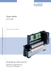
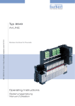
Type 8640
AirLINE
Modular valve terminal
Operating Instructions
Bedienungsanleitung
Manuel d‘utilisation
We reserve the right to make technical changes without notice.
Technische Änderungen vorbehalten.
Sous réserve de modifications techniques.
© Bürkert Werke GmbH, 2000–2014
Operating Instructions 1405/23_EU-en_00800665 / Original DE
Type 8640

Valve terminal type 8640
Table
1.
of
Contents
OPERATING INSTRUCTIONS.........................................................................................................................................................6
1.1. Symbols.......................................................................................................................................................................................6
2.
AUTHORIZED USE..............................................................................................................................................................................7
2.1. Restrictions................................................................................................................................................................................7
3.
BASIC SAFETY INSTRUCTIONS..................................................................................................................................................8
4.
GENERAL INFORMATION..............................................................................................................................................................10
4.1. Contact addresses..............................................................................................................................................................10
4.2. Warranty....................................................................................................................................................................................10
4.3. Information on the Internet.............................................................................................................................................10
5.
PRODUCT DESCRIPTION.............................................................................................................................................................11
5.1. Application area....................................................................................................................................................................11
5.2. General description............................................................................................................................................................11
5.3. Structure of the system....................................................................................................................................................12
6.
TECHNICAL DATA..............................................................................................................................................................................13
6.1. Operating conditions.........................................................................................................................................................13
6.2. Conformity...............................................................................................................................................................................13
6.3. Standards.................................................................................................................................................................................13
6.4. General technical data......................................................................................................................................................14
7.
8.
MODULES FOR CONVENTIONAL ELECTRICAL CONNECTION TECHNOLOGY.............................................15
FIELD BUS MODULE PROFIBUS DP/V1..............................................................................................................................18
8.1. PROFIBUS DP/V1, IP20 - overview............................................................................................................................18
8.2. PROFIBUS DP/V1, IP54 - overview............................................................................................................................20
8.3. DIP switch (PROFIBUS address)................................................................................................................................21
8.4. LED status display...............................................................................................................................................................22
9.
CONFIGURATION AND PARAMETER SETTINGS FOR PROFIBUS DP.................................................................24
9.1. Representation of the PROFIBUS-DP communication process................................................................24
9.2. Start-Up.....................................................................................................................................................................................25
9.3. Mode inputs............................................................................................................................................................................42
9.4. Input filter.................................................................................................................................................................................43
9.5. Special parameterization functions...........................................................................................................................43
9.6. Diagnosis..................................................................................................................................................................................44
9.7. Configuration and parameterization errors...........................................................................................................45
3
english
Type 8640

10.
BUS MODULE RIO SLAVE (RIO/VA).......................................................................................................................................46
10.1. Power supply (Power) RIO slave.................................................................................................................................47
10.2. Field bus connection RIO slave...................................................................................................................................47
10.3. LED Status Display.............................................................................................................................................................48
10.4. DIP switch settings.............................................................................................................................................................49
11.
FELDBUS MODULE DEVICENET..............................................................................................................................................52
11.1. DeviceNet, IP20 - overview.............................................................................................................................................52
11.2. DeviceNet, IP54 - overview.............................................................................................................................................54
11.3. Position of the DIP switches..........................................................................................................................................55
11.4. LED status display...............................................................................................................................................................56
11.5. Applications object.............................................................................................................................................................58
12.
CONFIGURATION AND PARAMETER SETTINGS FOR DEVICENET......................................................................59
12.1. Configuration of process data......................................................................................................................................59
12.2. Configuration of the safety position of solenoid valves if bus error........................................................59
12.3. Mode inputs............................................................................................................................................................................60
12.4. Input filter.................................................................................................................................................................................61
13.
FELDBUS MODULE CANOPEN.................................................................................................................................................62
13.1. CANopen, IP20 - overview..............................................................................................................................................62
13.2. CANopen, IP54 - overview..............................................................................................................................................63
13.3. Position of the DIP switches..........................................................................................................................................65
13.4. LED status display...............................................................................................................................................................66
14.
CONFIGURATION AND PARAMETER SETTINGS FOR CANOPEN..........................................................................68
14.1. Description of the CANopen field bus node.........................................................................................................68
14.2. Object overview....................................................................................................................................................................68
14.3. Detailed description of the supported objects....................................................................................................69
14.4. Input filter.................................................................................................................................................................................72
14.5. Mode inputs............................................................................................................................................................................72
14.6. Outputs......................................................................................................................................................................................74
14.7. Example for start-up..........................................................................................................................................................75
15.
FIELD BUS MODULES PROFINET IO, ETHERNET/IP AND MODBUS TCP.......................................................77
15.1. PROFINET IO, EtherNet/IP and MODBUS TCP, IP20 - overview...............................................................77
15.2. LED status display...............................................................................................................................................................79
15.3. Mode inputs............................................................................................................................................................................81
15.4. Input filter.................................................................................................................................................................................82
15.5. Fault Action and Fault Value..........................................................................................................................................83
15.6. Web server...............................................................................................................................................................................83
16.
CONFIGURATION AND PARAMETER SETTINGS FOR PROFINET IO...................................................................86
16.1. Hardware configuration by GSDML based on the example of Siemens STEP 7..............................86
4
16.2. Parameter settings for the PROFINET IO slave..................................................................................................89
english
Type 8640

17.
CONFIGURATION AND PARAMETER SETTINGS FOR ETHERNET/IP.................................................................91
17.1. Addressing..............................................................................................................................................................................91
17.2. EDS file......................................................................................................................................................................................91
17.3. Object model..........................................................................................................................................................................91
17.4. Configuration of process data......................................................................................................................................93
17.5. Applications object.............................................................................................................................................................94
18.
CONFIGURATION AND PARAMETER SETTINGS FOR MODBUS TCP.................................................................95
18.1. Modbus application protocol.........................................................................................................................................95
18.2. Modbus data model............................................................................................................................................................96
18.3. Mapping to TCP/IP..............................................................................................................................................................96
18.4. Connection-oriented structure.....................................................................................................................................96
18.5. 8640 objects...........................................................................................................................................................................97
19.
ELECTRICAL BASE MODULE OUTPUT.................................................................................................................................99
19.1. Collective socket..................................................................................................................................................................99
19.2. Valve outputs...................................................................................................................................................................... 100
19.3. Valve outputs with manual / automatic switching......................................................................................... 101
19.4. Valve outputs with external switch-off.................................................................................................................. 103
20.
ELECTRICAL BASE MODULE INPUT................................................................................................................................... 104
20.1. Terminal inputs for repeaters (initiators)............................................................................................................. 104
20.2. Plug inputs (M8 circular plugs) for repeaters (initiators)............................................................................ 105
21.
PNEUMATIC BASE MODULE................................................................................................................................................... 106
21.1. General description......................................................................................................................................................... 106
21.2. Pneumatic base module with integrated P shut-off...................................................................................... 107
22.
VALVES................................................................................................................................................................................................. 109
22.1. General description......................................................................................................................................................... 109
23.
INSTALLATION OF AIRLINE QUICK...................................................................................................................................... 112
23.1. Safety instructions........................................................................................................................................................... 112
23.2. Installation on standard rail......................................................................................................................................... 113
23.3. Installation of AirLINE Quick....................................................................................................................................... 113
23.4. Dimensions of the flange images for AirLINE Quick..................................................................................... 115
24.
PACKAGING, TRANSPORT........................................................................................................................................................ 117
25.
STORAGE............................................................................................................................................................................................ 117
26.
DISPOSAL.......................................................................................................................................................................................... 117
5
english
Type 8640
Operating instructions
1.
OPERATING INSTRUCTIONS
The operating instructions describe the entire life cycle of the device. Keep these instructions in a location which is
easily accessible to every user, and make these instructions available to every new owner of the device.
WARNING!
The operating instructions contain important safety information!
Failure to observe these instructions may result in hazardous situations.
• The operating instructions must be read and understood.
1.1.
Symbols
DANGER!
Warns of an immediate danger!
• Failure to observe the warning will result in a fatal or serious injury.
WARNING!
Warns of a potentially dangerous situation!
• Failure to observe the warning may result in serious injuries or death.
CAUTION!
Warns of a possible danger!
• Failure to observe this warning may result in a moderate or minor injury.
NOTE!
Warns of damage to property!
• Failure to observe the warning may result in damage to the device or the equipment.
Indicates important additional information, tips and recommendations.
Refers to information in these operating instructions or in other documentation.
→→designates a procedure which you must carry out.
6
english
Type 8640
Authorized use
2.
AUTHORIZED USE
Use of the valve terminal type 8640 for purposes other than those for which it is intended may represent a hazard to persons, nearby equipment and the environment.
• Do not use the device outdoors unprotected.
• Use according to the authorized data, service and operating conditions specified in the contract documents
and operating instructions. These are described in the chapter on “Technical data”.
• The device may be used only in conjunction with third-party devices and components recommended and
authorized by Bürkert.
• Correct transportation, storage, and installation, as well as careful use and maintenance are essential for reliable and faultless operation.
• Use the device only as intended.
The pneumatic modular valve terminal type 8640 was developed in compliance with accepted safety regulations and is state-of-the-art. Nevertheless, dangerous situations may occur.
2.1.
Restrictions
If exporting the system/device, observe any existing restrictions.
7
english
Type 8640
Basic safety instructions
3.
BASIC SAFETY INSTRUCTIONS
These safety instructions do not make allowance for any:
• Contingencies and events which may arise during the installation, operation and maintenance of the devices.
• Local safety regulations – the operator is responsible for observing these regulations, also with reference to the
installation personnel.
Danger – high pressure!
• Before dismounting pneumatic lines and valves, turn off the pressure and vent the lines.
Risk of electric shock!
• Before reaching into the device or the equipment, switch off the power supply and secure to prevent
reactivation!
• Observe applicable accident prevention and safety regulations for electrical equipment!
Risk of burns/risk of fire if used continuously through hot device surface!
• Keep the device away from highly flammable substances and media and do not touch with bare hands.
General Hazardous Situations.
To prevent injuries:
• Do not supply the medium connectors of the system with aggressive or flammable media.
• Do not physically stress the body (e.g. by placing objects on it or standing on it).
• Note that pipes and valves must not become detached in systems which are under pressure.
• Before any work is done on the system, always switch off the power supply.
• Design the pressure supply with the largest possible volume to prevent a pressure drop when the system is
switched on.
• Ensure that the system cannot be activated unintentionally.
• Installation and maintenance work may be carried out only by authorized technicians with the appropriate tools.
• After an interruption in the power supply or pneumatic supply, ensure that the process is restarted in a defined
or controlled manner.
• The device may be operated only when in perfect condition and in consideration of the operating instructions.
• The general rules of technology must be observed for application planning and operation of the device.
8
english
Type 8640
Basic safety instructions
NOTE!
Prevent a pressure drop!
To prevent a pressure drop, design the system pressure supply with the largest possible volume.
Electrostatic sensitive components/modules!
The device contains electronic components, which react sensitively to electrostatic discharge (ESD). Contact
with electrostatically charged persons or objects is hazardous to these components. In the worst case scenario,
they will be destroyed immediately or will fail after start-up.
• Observe the requirements in accordance with EN 61340-5-1 and 5-2 to minimize/avoid the possibility of
damage caused by a sudden electrostatic discharge!
• Also, ensure that you do not touch electronic components when the power supply voltage is present!
9
english
Type 8640
General information
4.
GENERAL INFORMATION
4.1.
Contact addresses
Germany
Bürkert Fluid Control Systems
Sales Center
Christian-Bürkert-Str. 13-17
D-74653 Ingelfingen
Tel. + 49 (0) 7940 - 10 91 111
Fax + 49 (0) 7940 - 10 91 448
E-mail: [email protected]
International
Contact addresses can be found on the final pages of the printed operating instructions.
And also on the Internet at:
www.burkert.com
4.2.
Warranty
The warranty is only valid if the device is used as intended in accordance with the specified application conditions.
4.3.
Information on the Internet
The operating instructions and data sheets for Type 8640 can be found on the Internet at:
www.buerkert.com
10
english
Type 8640
Product description
5.
PRODUCT DESCRIPTION
5.1.
Application area
The valve terminal type 8640 is intended for use in an industrial environment. The valves can be combined very easily
and efficiently thanks to the modular design.
DANGER!
Risk of electric shock!
• Before reaching into the device or the equipment, switch off the power supply and secure to prevent
reactivation.
• Observe applicable accident prevention and safety regulations for electrical equipment.
5.2.
General description
Thanks to its strictly modular construction in terms of the pneumatic and electrical interfaces the type 8640 valve
terminal is suitable for a wide range of tasks, including complex ones. By aligning pneumatic modules in sequence
with varying numbers of valves it is possible to configure up to 24 valve functions on one valve terminal.
The electrical connection technology can be implemented as required via field bus interfaces, collective sockets
(parallel connection technology) or multi-pole interfaces. The valves are designed for various usage scenarios. The
body and connection modules are manufactured using high quality plastic (polyamide) and can be connected and
released easily thanks to an integrated attachment mechanism.
Figure 1:
Example of usage for pneumatic modular valve terminal type 8640
11
english
Type 8640
Product description
5.3.
Structure of the system
Each valve terminal is configured according to customer requirements. To ensure optimal performance for the task
in question a large range of electrical and fluid-related components is available.
Electric cable termination module
Terminal module for feedback indicator
Extension module for electrical inputs
Multipole feedback indicator inputs (initiators)
Electric cable
termination module
Electric base module
Field bus module
Multipole valve outputs
Pneumatic connection
module
Multiple connection module
Pneumatic base module
Pneumatic
connection module
Valves of type 6525 (5/2-way)
Figure 2:
Example for the configuration of the modular electric valve terminal type 8640
12
english
Type 8640
Technical data
6.
TECHNICAL DATA
6.1.
Operating conditions
Ambient temperature: 0 ... +50 °C
Storage temperature: -20 ... +60 °C
Nominal operating mode: Long-term operation (100% ED)
Operating voltage: 24 V / DC ± 10 %, residual ripple for field bus interface 1 Vss
Protection class: 3 in accordance with VDE 0580
Power consumption:
Power consumption is dependent on the type of electrical connection technology.
1. For the collective socket (parallel connection technology), and multi-pole interfaces power consumption is
determined by the valve type used, but limited to a total current of 3 A maximum. For a multi-pole solution
combined with repeaters there is a further summed current, also limited to a maximum of 3 a.
2. For the field bus interface the total current can be determined according to the equation:
l total = I base + (n x I valve) + (m x l repeater)
I basebase current dep. on field bus system
PROFIBUS-DP V1
200 mA
DeviceNet
200 mA
CANopen
200 mA
n
number of valves
m
number of repeaters
I valve
nominal current of valve type
l repeaterpower consumption of repeater
(m x I repeater) = max. 650 mA
NOTE!
Always use safety low voltage according to protection class 3 VDE 0580!
6.2.
Conformity
Type 8640 conforms with the EC Directives according to the EC Declaration of Conformity.
6.3.
Standards
The applied standards, which verify conformity with the EC Directives, can be found on the EC-Type Examination
Certificate and / or the EC Declaration of Conformity.
13
english
Type 8640
Modules for conventional electrical
connection technology
6.4.
General technical data
6.4.1.
Add-on dimension 11 mm
Add-on dimension
11 mm
Operating principle
Valve
C/D (3/2-way)
Type 6524
Operating principle
Valve
H (5/2-way)
Type 6525
Flow rate [l/min]
2xC (2x3/2-way)
Type 6524
LN (5/3-way)
Type 0460
H (5/2-impulse)
Type 0460
300
300
200
2.5 ... 7
2,5 ... 10
2.5 ... 7
2,5 ... 10
2.5 ... 7
1
2 x 0.25
2 x 0.9
43/28
2 x 43/18
2 x 41/-
Valve locations
max. 24
max. 12
max. 12
Repeater
max. 32
max. 32
max. 32
Electrical modules
6-fold*, 8-fold, 12-fold
6-fold*, 8-fold, 12-fold
6-fold*, 8-fold, 12-fold
Pneumatic modules
2-fold, 8-fold
2-fold, 8-fold
2-fold, 8-fold
IP40
IP20
IP40
IP20
IP40
IP20
Pressure range [bar]
Power rating [W]
Current before/after power
reduction [mA]
Protection class in terminal
design
* Configuration with 6-fold modules on request
6.4.2.
Add-on dimension 16.5 mm and 19 mm
Add-on dimension
16,5 mm
19 mm
Operating principle
Valve
C/D (3/2-way)
Type 6526
C/D (3/2-way)
Type 5470
Operating principle
Valve
H (5/2-way)
Type 6527
G (4/2-way)
Type 5470
700
300
2 ... 10
2 ... 8
Flow rate [l/min]
Pressure range [bar]
Power rating [W]
Current before/after power
reduction [mA]
1
2
1
2
42/33
85/52
42/-
84/-
Valve locations
max. 24
max. 24
Repeater
max. 32
max. 32
Electrical modules
4-fold, 6-fold, 8-fold
2-fold, 5-fold, 6-fold
Pneumatic modules
2-fold, 4-fold
2-fold, 3-fold
IP54
IP20
IP54
IP20
Protection class in terminal
design
14
english
Type 8640
Modules for conventional electrical
connection technology
7.
MODULES FOR CONVENTIONAL
ELECTRICAL CONNECTION TECHNOLOGY
7.4.1.
Collective socket module
The collective socket module serves as a central connecting element for ground and functional earth.
Allocation plan
Ground
Functional earth
Figure 3:
Collective socket module for valve outputs
7.4.2.
Multi-pole connection for valve outputs
13
12
11
10
9
8
7
6
5
4
3
2
1
Figure 4:
25
24
23
22
21
20
19
18
17
16
15
14
Pin 1 Pin 2 Pin 3 Pin 4 Pin 5 Pin 6 Pin 7 Pin 8 Pin 9 Pin 10 Pin 11 Pin 12 Pin 13 Pin 14 Pin 15 Pin 16 Pin 17 Pin 18 Pin 19 Pin 20 Pin 21 Pin 22 Pin 23 Pin 24 Pin 25 Valve 1
Valve 2
Valve 3
Valve 4
Valve 5
Valve 6
Valve 7
Valve 8
Valve 9
Valve 10
Valve 11
Valve 12
Valve 13
Valve 14
Valve 15
Valve 16
Valve 17
Valve 18
Valve 19
Valve 20
Valve 21
Valve 22
Valve 23
Valve 24*
Ground
Multi-pole module for valve outputs D-SUB IP54 and allocation of the D-SUB plug
* Multi-pole for manual automation only 23 bit, as Pin 24 used for permanent 24 V.
15
english
Type 8640
Modules for conventional electrical
connection technology
Accessories
D-SUB plug
25-pin
IP54 5 m cable
Id.-No. 917 494
D-SUB plug
25-pin
IP54 10 m cable
Id.-No. 917 495
Colour code for D-SUB cable
The wires are soldered 1:1 to the D_SUB plug, i.e. wire 1 ws to Pin 1 D-SUB etc.
Pin/Wire
Wire colour
Code
Pin/Wire
Wire colour
Code
1
white
ws
14
brown-green
brgn
2
brown
br
15
white-yellow
wsge
3
green
gn
16
yellow-brown
gebr
4
yellow
ge
17
white-grey
wsgr
5
grey
gr
18
grey-brown
grbr
6
pink
rs
19
white-pink
wsrs
7
blue
bl
20
pink-brown
rsbr
8
red
rt
21
white-blue
wsbl
9
black
sw
22
brown-blue
brbl
10
violet
vi
23
white-red
wsrt
11
grey-pink
grrs
24
brown-red
brrt
12
red-blue
rtbl
25
white-black
wssw
13
white-green
wsgn
7.4.3.
Multi-pole connection with repeater inputs (initiators)
15
14
13
12
11
10
9
8
7
6
5
4
3
2
1
Figure 5:
30
29
28
27
26
25
24
23
22
21
20
19
18
17
16
44
43
42
41
40
39
38
37
36
35
34
33
32
31
Pin 1 Pin 2 Pin 3 Pin 4 Pin 5 Pin 6 Pin 7 Pin 8 Pin 9 Pin 10 Pin 11 Pin 12 Pin 13 Pin 14 Pin 15 Pin 16 Pin 17 Pin 18 Pin 19 Input 1
Input 2
Input 3
Input 4
Input 5
Input 6
Input 7
Input 8
Input 9
Input 10
Input 11
Input 12
Input 13
Input 14
Input 15
Input 16
Input 17
Input 18
Input 19
Pin 20 Pin 21 Pin 22 Pin 23 Pin 24 Pin 25 Pin 26 Pin 27 Pin 28 Pin 29 Pin 30 Pin 31 Pin 32 ...
Pin 43 Pin 44 Multi-pole module for repeater inputs D-SUB IP54 and allocation of the D-SUB plug
16
english
Input 20
Input 21
Input 22
Input 23
Input 24
Input 25
Input 26
Input 27
Input 28
Input 29
Input 30
Input 31
Input 32
24 V
Ground
Type 8640
Modules for conventional electrical
connection technology
Accessories
D-SUB plug
44-pin
IP54 5 m cable
Id.-No. 917 496
D-SUB plug
44-pin
IP54 10 m cable
Id.-No. 917 497
Colour code for D-SUB cable
The wires are soldered 1:1 to the D_SUB plug, i.e. wire 1 ws to Pin 1 D-SUB etc.
Pin/Wire
Wire colour
Code
Pin/Wire
Wire colour
Code
1
white
ws
23
white-red
wsrt
2
brown
br
24
brown-red
brrt
3
green
gn
25
white-black
wssw
4
yellow
ge
26
brown-black
brsw
5
grey
gr
27
grey-green
grgn
6
pink
rs
28
yellow-grey
grgr
7
blue
bl
29
pink-green
rsgn
8
red
rt
30
yellow-pink
gers
9
black
sw
31
green-blue
gnbl
10
violet
vi
32
yellow-blue
gebl
11
grey-pink
grrs
33
green-red
gnrt
12
red-blue
rtbl
34
yellow-red
gert
13
white-green
wsgn
35
green-black
gnsw
14
brown-green
brgn
36
yellow-black
gesw
15
white-yellow
wsge
37
grey-blue
grbl
16
yellow-brown
gebr
38
pink-blue
rsbl
17
white-grey
wsgr
39
grey-red
grrt
18
grey-brown
grbr
40
pink-red
rsrt
19
white-pink
wsrs
41
grey-black
grsw
20
pink-brown
rsbr
42
pink-black
rssw
21
white-blue
wsbl
43
blue-black
blsw
22
brown-blue
brbl
44
red-black
rtsw
17
english
Type 8640
Field bus module PROFIBUS DP/V1
8.
FIELD BUS MODULE PROFIBUS DP/V1
8.1.
PROFIBUS DP/V1, IP20 - overview
Power Supply
LED Status Display
Functional earth
DIP Switches
Field bus connection
Connection for RIO
slave bus module –
see “10. Bus Module
Rio Slave (RIO/VA)”,
page 46
Figure 6:
Overview of field bus module PROFIBUS DP IP20
The DIP switches can be operated through the covering film.
8.1.1.
Power supply IP20
The 4-pole plug-in connector for the power supply is configured as follows:
24 V DC (2)
valves /
outputs
24 V DC (4)
logic
Pin 1
Electronics
Inputs
Pin 4
Valves /
Outputs
GND (3)
logic
GND (1)
valves /
outputs
Pin 1
-
2 3 4
+ -
Valves /
Outputs
Figure 7:
Power supply configuration
Figure 8:
+
Logic
inputs
Cutaway POWER connection
Pin 2 of the power supply must be supplied with a 4 A medium time-lag fuse; Pin 4 with 1 A.
18
english
Type 8640
Field bus module PROFIBUS DP/V1
NOTE!
To ensure electromagnetic compatibility (EMC) connect the screw terminal FE (functional earth) to earth
potential using a short cable (30 cm).
Accessories
Plug-in connector (No. 918 226) for power supply (supplied).
8.1.2.
IP20 field bus connection
A 9-pole D-SUB connection is used for an IP20 protection class field bus connection. The following shows the
wiring layout according to Standard 19245 Part 1.
Pin-No.
Signal name (socket in device,
plug on cable)
Description
1
n.c.
-
2
n.c.
-
3
RxD/TxD-P
Receive / Send data P
4
CNTR-P (RTS)
Request to send (repeater control
signal)
5
DGND
Data reference potential
6
+5 V
Supply voltage - plus
7
n.c.
-
8
RxD/TxD-N
Receive / Send data N
9
n.c.
-
19
english
Type 8640
Field bus module PROFIBUS DP/V1
8.2.
PROFIBUS DP/V1, IP54 - overview
Power Supply
LED Status Display
Functional earth
DIP Switches
Field bus connection
Figure 9:
Overview field bus module PROFIBUS-DP IP54
The DIP switches can be operated through the covering film.
8.2.1.
Power supply IP54
The 4-pole circular plug-in connector for the power supply is configured as follows:
24 V DC (1)
valves /
outputs
24 V DC (2)
logic
Pin 1: +24 V - valves (outputs)
Electronics
GND (3)
logic
Inputs
Valves /
Outputs
Pin 2: +24 V - logic + inputs
Pin 3: GND - logic + inputs
Pin 4: GND - valves (outputs)
GND (4)
valves /
outputs
Figure 10:
Power supply configuration
Pin 1 of the power supply must be supplied with a 4 A medium time-lag fuse; Pin 2 with 1 A.
NOTE!
To ensure electromagnetic compatibility (EMC) connect the screw terminal FE (functional earth) to earth
potential using a short cable (30 cm).
20
english
Type 8640
Field bus module PROFIBUS DP/V1
8.2.2.
IP54 field bus connection
The M12 plug-in system is used for an IP54 protection class field bus connection. To avoid confusion between
the bus and the supply slot the Reserve Key coding is used. Layout for plugs and sockets:
Pin No.
Signal
Description
1
VP
2
RxDx / TxD-N
3
DGND
4
RxDx / TxD-P
5
Shielding
Shielding / protective earth
Thread
Shielding
Shielding / protective earth
Supply voltage - plus (P5V)
Receive / Send data N, A connection
Data transmission potential (reference potential to VP)
Receive / Send data P, B connection
Accessories
PROFIBUS plug-in connector (configurable), socket
(Reserve Key coding)
PROFIBUS plug-in connector (configurable), plug
(Reserve Key coding)
Id.-No. 918 447
Id.-No. 918 198
for connection without T-piece this ID is needed
PROFIBUS T-piece (12 MBaud)
Id.-No. 902 098
M12 power supply, socket
Id.-No. 902 552
M12 terminal resistance, plug
Id.-No. 902 553
8.3.
DIP switch (PROFIBUS address)
→→Set the DIP switch through the film using a screwdriver (the film is very durable).
DIP
Value
Description
Note
1 (above)
1
PROFIBUS address
2
2
PROFIBUS address
The PROFIBUS address equals the sum of all the
DIP switch values from 1 to 7 in 'ON' setting.
...
...
PROFIBUS address
'ON' setting = DIP switch to the right
...
...
6
32
PROFIBUS address
7
64
PROFIBUS address
8 (below)
-
reserved
Switch to 'OFF'
21
english
Type 8640
Field bus module PROFIBUS DP/V1
8.4.
LED status display
BUS_FAULT (BF)
BUS_OK (BO)
FAILURE_NUMBER (FN)
FAILURE_SELECT (FS)
U_LOGIK_OK (Ul)
U_TREIBER_OK (U0)
Figure 11:
LED state display (detail)
Abbreviation
Colour
Description
BO
green
Bus OK
BF
red
Bus Fault
FS
yellow
Failure Select
FN
red
Failure Number
Ul
green
U LOGIC OK
U0
green
U driver OK
Explanation
Bus communication active
Bus fault
Determines the function of the FN LED:
FS lit up: FN displays fault type
FS not lit up: FN displays failure number
The number of flash impulses indicates the fault type or the
failure number depending on whether FS is lit up or not
Voltage for logic supply, inputs and bus interface present
Voltage for outputs present
Normal state
LED
Status
BUS (BO)
ON
BUS (BF)
OFF
FS
OFF
FN
OFF
U0
ON
UL
ON
Description
Error-free operation of the valve
terminal on PROFIBUS DP
bus fault
LED
Status
BUS (BO)
OFF
BUS (BF)
ON
FS
OFF
FN
OFF
U0
ON
UL
ON
22
english
Description
Signal monitoring time on valve
terminal elapsed without receipt
of signal from master
Fault cause / remedial action
During operation:
→→Check master (control) and bus cable
During start-up:
→→Check network configuration on master
and station address on terminal
Type 8640
Field bus module PROFIBUS DP/V1
8.4.1.
Errors and warnings displayed via FN (Failure Number)
and FS (Failure Select) LEDs
The following table contains errors and warning messages displayed via the FN (Failure Number) and FS
(Failure Select) LEDs.
The error type is indicated by the number of times FN flashes when FS is set to ON.
The error number is indicated by FN flashing when FS is set to OFF.
Number FN
when FS ON
error type
Number FN
when FS OFF
error number
Description
Remedial action
Parameterization error (Set_Prm_Telegramm)
1
2
1
3
Too many inputs for one valve terminal
(bitwise composition)
→→Check user parameters and
Too many outputs for one valve terminal
(bitwise composition)
→→Check user parameters and
Parameterization telegram too long
→→Check user parameters and
DIP switch
DIP switch
DIP switch
4
Parameterization telegram too short
→→Check user parameters and
DIP switch
Configuration error (Chk_Cfg_Telegramm)
1
Too many inputs for one valve terminal
→→Check identification bytes and
2
Too many outputs for one valve terminal
→→Check identification bytes and
DIP switch
DIP switch
2
3
4
5
Too few inputs for one valve terminal
(preset in parameterization telegram)
→→Check identification bytes and
Too few outputs for one valve terminal
(preset in parameterization telegram)
→→Check identification bytes and
An identifier has the wrong code
→→Check identification bytes and
DIP switch
DIP switch
DIP switch
Main terminal error
3
1
No supply voltage for main terminal
outputs
→→Check supply voltage
2
Setting for station address is outside
permitted range (0 ... 125)
→→Check PROFIBUS address
Error accessing EEPROM
→→Replacement of electronics
3
on main terminal
may be necessary
Peripheral terminal error
1
No supply voltage for peripheral terminal
outputs
→→Check supply voltage
2
Complete failure of a peripheral terminal
→→Check peripheral terminal
4
RIO bus
After the error has been rectified the valve terminal must be reset by briefly shutting down the supply
voltage.
23
english
Type 8640
Configuration and parameter
settings for PROFIBUS DP
9.
CONFIGURATION AND PARAMETER
SETTINGS FOR PROFIBUS DP
The purpose of the bus system is to enable rapid connection of the decentralized periphery (valve terminal) with
the central master (control). As well as input and output data, parameter, configuration and diagnostic data is also
transmitted.
Many PROFIBUS masters (controls) need a configuration program which lays down the network structure. These
programs require the device base data file (GSD file).
9.1.
Representation of the PROFIBUS-DP
communication process
Start
The diagnostics routine is requested for as long as is necessary until the component responds and is not blocked by
another master.
Read diagnosis
Diagnosis OK ?
No
Yes
Master transmits parameterization data
- bus-specific data (e.g. signal monitoring)
- User-specific parameterization data (as required) errors are
displayed in the diagnosis.
Write parameter
Master transmits required configuration
Required configuration is compared to actual configuration
in slave
Errors are displayed in the diagnosis.
Write configuration
Master reads diagnosis.
Read diagnosis
Yes
Error ?
If there is a parameterisation or configuration error, the communication is restarted from the beginning.
No
Cyclical data exchange
24
Figure 12:
If the slave is in data exchange mode then a cyclical
exchange of data takes place.
Simplified representation of the PROFIBUS-DP communication process
english
Type 8640
Configuration and parameter
settings for PROFIBUS DP
9.2.
Start-Up
Setting the PROFIBUS address
via DIP switch
DP bus
DIP Switches
DP main
terminal
DP bus
Are extension terminals (RIO)
present1)
No
DP main
terminal
No
Should the default
input mode or filter be
modified
bytewise
Yes
RIO extension
Yes
How should inputs /
outputs be put
together2)
bitwise
Parameterization
1)
Configuration
Parameterization
Parameterization
Example
1
2
3
4
Configuration
Configuration
Example
5
Example
6
Extension terminals are connected to the valve terminal via the RIO interface
Advantage of bitwise distribution:
1. If the number of inputs or outputs does not correspond to the byte pattern then bits remain unused with bytewise configuration. For instance, with a valve terminal with 4 valves and a valve terminal with 10 valves that amounts to 10 bits with
bytewise configuration (4+6 bits), because the first valve terminal requires 1 byte and the second one requires 2 bytes.
With bitwise distribution the outputs can be combined. This means that only 2 bytes are needed and 2 bits remain unused.
2. The bitwise composition means that the identifiers / slots (assignation in process image) can be selected at will in the
configuration program.
2) Figure 13:
Start-Up
25
english
Type 8640
Configuration and parameter
settings for PROFIBUS DP
9.2.1.
Parameterization without extension terminal
(hex parameter / User_Prm_Data)
The default value for the parameterization is:
• Extension terminal
none
• Input mode
normal inputs
• Filter
ON
The parameterization can be used to modify the settings selected for the input mode and the filter.
Bit 7
Byte
Bit 6
Bit 5
Bit 4
Bit 3
Bit 2
Bit 1
Bit 0
Bus parameters (normal parameters) 7 bytes
Lock_Rep
Unlock_Re
Sync_Req
Freeze_Req
WD_On
00 min TSDR and slave spec. data
01 release for other masters
10 lock for other masters
11 release for other masters
Slave being
operated in
Sync mode
Slave being
operated in
Freeze mode
Signal monitoring
0: deactivated
1: activated
2
WD_Fact_1
(range 1-255 signal monitoring in [s] = 10 ms x WD_Fact_1 x WD_Fact_2)
3
WD_Fact_2
(range 1-255 signal monitoring in [s] = 10 ms x WD_Fact_1 x WD_Fact_2)
4
TSDR
(time in Tbits in which the slave may respond. At least 11 Tbit; 0 old value remains)
5
Ident_Number high byte
(manufacturer identification 00 Hex)
6
Ident_Number low byte
(manufacturer identification 81 Hex)
7
Group_Ident
(For group generation; each bit represents one group.)
reserved
reserved
reserved
User_Parm_Data (DPV1_Status)
8
DPV1_Status_1
9
DPV1_Status_2
10
DPV1_Status_3
User_Prm_Data (user parameters)
11
See table below:
Byte 11 User_Prm_Data (user parameters)
Input mode
Input filter OFF
Input filter ON
no inputs
04 hex
44 hex
normal inputs
14 hex
54 hex
shifted inputs
24 hex
64 hex
halved inputs
34 hex
74 hex
For a description of the input modes, refer to Section “9.3. Mode inputs”Mode inputs".
Many configuration tools do not allow for direct access to bytes 1 to 7. For Siemens (Step 5 and Step 7)
the parameters (Hex parameters) start at byte 8.
26
english
Type 8640
Configuration and parameter
settings for PROFIBUS DP
9.2.2.
Configuration of the valve terminal without extension
terminals
The settings of the desired configuration, i.e. setting of various identifiers, is generally done with the help of the GSD
file. Up to 7 identifiers (slots) can be assigned.
When the configuration is written, the number of input and output bytes is set in the process image and checked
against permitted limits. By using different identifiers the user can assign the input and output bytes in the
process image at will.
A valve terminal has a maximum of 32 inputs and a maximum of 24 outputs. This corresponds to a maximum of 4
input bytes and a maximum of 3 output bytes. For this reason never more than the above specified number of input /
output bytes may be configured in the process image of a valve terminal- However, taking the limits specified above
into account (32 inputs, 24 outputs; 4 input bytes, 3 output bytes) it is possible to configure both less than, but also
more than the number of input / output bytes that are actually physically present on the valve terminal.
Example:
Physically present
16 valves
Configuration
Consequence
1 bytes
Only valves 1 to 8 can be addressed
2 bytes
Valves 1 to 16 can be addressed
3 bytes
Valves 1 to 16 can be addressed,
1 byte remains unusable in process image
4 bytes
Configuration errors
Manual configuration
If no GSD file is available the configuration must be performed manually. The following specifications apply. One
configuration telegram can contain one or several identifications, whereby the user can make the necessary allocations at will. the identifications have the following structure:
Bit 7
Consistency
0 = byte/word
1 = total length
Bit 6
bytes/words
0 = bytes
1 = words (2 bytes)
Bit 5 - 4
Bit 3 - 0
Input/Output
00 = spec. identifier format
01 = input
10 = output
11 = input/output
Data length (number)
0000 = 1 byte/word
...
0010 = 3 bytes/words
...
1111 = 16 bytes/words
Hex
Decimal
Description
10
016
1 byte input; consistency via byte
11
017
2 bytes input; consistency via byte
12
018
3 bytes input; consistency via byte
13
019
4 bytes input; consistency via byte
20
032
1 byte output; consistency via byte
21
033
2 bytes output; consistency via byte
22
034
3 bytes output; consistency via byte
00
000
Placeholder (empty position)
27
english
Type 8640
Configuration and parameter
settings for PROFIBUS DP
Example 1 - valve terminal with 16 valves (outputs) and 32 repeaters (inputs)
• PROFIBUS-DP address 4
• The valves 1-16 are assigned to outputs (PAA) bytes 11-12 in the process image.
• The repeaters 1-32 are assigned to inputs (PAE) bytes 20-23 in the process image.
• Mode: Normal input mode
• Input filter active
DIP Switches
1
2
3
4
5
6
7
8
OFF
OFF
ON
OFF
OFF
OFF
OFF
OFF
User parameter byte 11 User_Prm_Data 54 hex
Configuration:
Byte No. (slot)
1* (0**)
2 (1)
Identification in Hex (Dec)
13 (019)
21 (033)
Process image output (PAA)
11-12
Process image input (PAE)
20-23
* Standard
** Siemens
Allocation of inputs and outputs to control process image
Process image
28
Figure 14:
Outputs (PAA)
Allocation of inputs and outputs to control process image
english
Valve
Valve
Valve
Valve
Valve
Valve
Valve
Valve
Inputs (PAE)
Valve
Valve
Valve
Valve
Valve
Valve
Valve
Valve
Process image
Type 8640
Configuration and parameter
settings for PROFIBUS DP
Example 2 - valve terminal with 16 valves (outputs) and 32 repeaters (inputs)
• PROFIBUS-DP address 5
• The valves 1-8 are assigned to outputs (PAA) byte 11 in the process image.
• The valves 9-16 are assigned to outputs (PAA) byte 20 in the process image.
• The repeaters 1-8 are assigned to inputs (PAE) byte 10 in the process image.
• The repeaters 9-16 are assigned to inputs (PAE) byte 15 in the process image.
• The repeaters 17-32 are assigned to inputs (PAE) bytes 20-21 in the process image.
• Mode: Normal input mode
• Input filter active
DIP Switches
1
2
3
4
5
6
7
8
ON
OFF
ON
OFF
OFF
OFF
OFF
OFF
User parameter byte 11 User_Prm_Data 54 hex
Configuration:
Byte No. (slot)
1 (0)
2 (1)
3 (2)
4 (3)
5 (4)
Identification in Hex (Dec)
10 (016)
10 (016)
11 (017)
20 (032)
20 (032)
11
20
Process image output (PAA)
Process image input (PAE)
10
15
20-21
Allocation of inputs and outputs to control process image
Valve
Valve
Valve
Valve
Valve
Valve
Valve
Valve
Valve
Valve
Valve
Valve
Valve
Valve
Valve
Valve
Process image Inputs (PAE)
Process image Outputs (PPA)
Figure 15:
Allocation of inputs and outputs to control process image
29
english
Type 8640
Configuration and parameter
settings for PROFIBUS DP
Example 3 - valve terminal with 16 valves (outputs) and 32 repeaters (inputs)
• PROFIBUS-DP address 6
• The valves 1-16 are assigned to outputs (PAA) bytes 11+12 in the process image.
• Repeaters 1, 3, 5, ... 15 are assigned to inputs (PAE) byte 10 in the process image.
• Repeaters 2, 4, 6, ... 16 are assigned to inputs (PAE) byte 16 in the process image.
• Repeaters 1, 17, 19, ... 31 are assigned to inputs (PAE) byte 11 in the process image.
• Repeaters 1, 18, 20, ... 32 are assigned to inputs (PAE) byte 17 in the process image.
• Mode: Shifted inputs
• Input filter active
DIP Switches
1
2
3
4
5
6
7
8
OFF
ON
ON
OFF
OFF
OFF
OFF
OFF
User parameter byte 11 User_Prm_Data 64 hex
Configuration:
Byte No. (slot)
1 (0)
2 (1)
3 (2)
4 (3)
5 (4)
Identification in Hex (Dec)
10 (016)
10 (016)
10 (016)
10 (016)
21 (032)
Process image output (PAA)
11-12
Process image input (PAE)
10
16
11
Allocation of inputs and outputs to control process image
Valve
Valve
Valve
Valve
Valve
Valve
Valve
Valve
Valve
Valve
Valve
Valve
Valve
Valve
Valve
Valve
Process image Inputs (PAE)
Process image Outputs (PPA)
30
Figure 16:
Allocation of inputs and outputs to control process image
english
17
Type 8640
Configuration and parameter
settings for PROFIBUS DP
Example 4 - valve terminal with 16 valves (outputs) and 32 repeaters (inputs), every second repeat signal
not taken into account
• PROFIBUS-DP address 7
• The valves 1-8 are assigned to outputs (PAA) byte 17 in the process image.
• The valves 9-16 are assigned to outputs (PAA) byte 10 in the process image.
• Repeaters 1, 3, 5, ... 15 are assigned to inputs (PAE) byte 18 in the process image.
• Repeaters 1, 17, 19, ... 31 are assigned to inputs (PAE) byte 21 in the process image.
• Mode: Halved inputs
• Input filter active
DIP Switches
1
2
3
4
5
6
7
8
ON
ON
ON
OFF
OFF
OFF
OFF
OFF
User parameter byte 11 User_Prm_Data 74 hex
Configuration:
Byte No. (slot)
1 (0)
2 (1)
3 (2)
4 (3)
Identification in Hex (Dec)
10 (016)
10 (016)
20 (032)
20 (032)
17
10
Process image output (PAA)
Process image input (PAE)
18
21
Allocation of inputs and outputs to control process image
Valve
Valve
Valve
Valve
Valve
Valve
Valve
Valve
Valve
Valve
Valve
Valve
Valve
Valve
Valve
Valve
Process image Inputs (PAE)
Process image Outputs (PPA)
Figure 17:
Allocation of inputs and outputs to control process image
31
english
Type 8640
Configuration and parameter
settings for PROFIBUS DP
9.2.3.
Parameterization of the valve terminal with extension
terminal - bytewise composition of the inputs and outputs
The default value for the parameterization of the main terminal is:
• Extension terminal - none (must be adjusted bytewise on RIO)
• Input mode - normal inputs
• Filter - ON
When extension terminals are used the parameterization option extension terminals RIO bytewise must be
selected.
The parameterization can be used to modify the settings selected for the input mode and the filter.
Further, you may set the length of the device-related diagnosis, whereby the long diagnosis only makes sense
when more than four extension terminals are used. The following settings are permitted in the parameter telegram:
User parameter byte 11 User_Prm_Data
Input mode
Input filter OFF
Input filter ON
Input filter OFF
long diagnosis
Input filter ON long
diagnosis
no inputs
05 hex
45 hex
85 hex
C5 hex
normal inputs
15 hex
55 hex
95 hex
D5 hex
shifted inputs
25 hex
65 hex
A5 hex
E5 hex
halved inputs
35 hex
75 hex
B5 hex
F5 hex
For a description of the input modes and the input filter refer to Section "9.3 Input modes".
9.2.4.
Configuration of the valve terminal with extension terminal bytewise composition of the inputs and outputs
The settings of the desired configuration, i.e. setting of various identifiers, is generally done with the help of the GSD
file. Up to 18 identifiers (slots) can be assigned. Each extension terminal starts with a new byte in the process image.
For the main terminal and for each extension terminal 2 identifications are used, i.e. for bytewise configuration the
identifications for a single valve terminal must be contiguous. Each valve terminal can be configured with 4 input
bytes and 3 output bytes.
If there are no inputs / outputs present for a valve terminal, the identification 0 (space) must be entered
here.
Manual configuration: If no GSD file is available the configuration must be performed manually. The following
specifications apply:
Bit 7
Bit 6
Bit 5-4
Bit 3-0
Consistency
Bytes / Words
Input / Output
Length (amount of data)
0 = byte/word
1 = total length
0 = bytes
1 = words (2 bytes)
00 = spec. identifier format
01 = input
10 = output
11 = input/output
0000 = 1 byte / word
...
0010 = 3 bytes / words
...
1111 = 16 bytes / words
32
english
Type 8640
Configuration and parameter
settings for PROFIBUS DP
Examples:
Hex
Decimal
Description
10
016
1 byte input; consistency via byte
11
017
2 bytes input; consistency via byte
12
018
3 bytes input; consistency via byte
13
019
4 bytes input; consistency via byte
20
032
1 byte input; consistency via byte
21
033
2 bytes input; consistency via byte
22
034
3 bytes input; consistency via byte
00
000
Placeholder (empty position)
Configuration
Slot
Function
1 (0)
Inputs
2 (1)
Outputs
3 (2)
Inputs
4 (3)
Outputs
5 (4)
Inputs
6 (5)
Outputs
7 (6)
Inputs
8 (7)
Outputs
9 (8)
Inputs
10 (9)
Outputs
11 (10)
Inputs
12 (11)
Outputs
13 (12)
Inputs
14 (13)
Outputs
15 (14)
Inputs
16 (15)
Outputs
17 (16)
Inputs
18 (17)
Outputs
Valve terminals
Main terminal
Extension terminal 0
(DIP switch on EI 0 S1=OFF, S2=OFF, S3=OFF)
Extension terminal 1
(DIP switch on EI 1 S1=ON, S2=OFF, S3=OFF)
Extension terminal 2
(DIP switch on EI 2 S1=OFF, S2=ON, S3=OFF)
Extension terminal 3
(DIP switch on EI 3 S1=ON, S2=ON, S3=OFF)
Extension terminal 4
(DIP switch on EI 4 S1=OFF, S2=OFF, S3=ON)
Extension terminal 5
(DIP switch on EI 5 S1=ON, S2=OFF, S3=ON)
Extension terminal 6
(DIP switch on EI 6 S1=OFF, S2=ON, S3=ON)
Extension terminal 7
(DIP switch on EI 7 S1=ON, S2=ON, S3=ON)
33
english
Type 8640
Configuration and parameter
settings for PROFIBUS DP
Example 5 - main terminal and 3 extension terminals Main terminal with 8 valves (outputs) and 16
repeaters (inputs)
• PROFIBUS-DP address 8
• The valves 1-8 are assigned to outputs (PAA) byte 30 in the process image.
• The repeaters 1-16 are assigned to inputs (PAE) bytes 15+16 in the process image.
• Mode: Normal input mode
• Input filter active
• RIO interface
DIP switch main terminal
1
2
3
4
5
6
7
8
OFF
OFF
OFF
ON
OFF
OFF
OFF
OFF
Extension terminal 0 with 8 valves (outputs) and 16 repeaters (inputs)
• Address 0 (extension terminal 0 always has the address 0)
• The valves 1-8 are assigned to outputs (PAA) byte 12 in the process image.
• The repeaters 1-16 are assigned to inputs (PAE) bytes 20+21 in the process image.
• Mode: Normal input mode
• Input filter active
DIP switch extension terminal 0
1
2
3
4
5
6
7
8
9
10
11
12
OFF
OFF
OFF
ON
OFF
OFF
ON
OFF
ON
OFF
ON
OFF
Extension terminal 1 with 8 valves (outputs) and 16 repeaters (inputs)
• Address 1 (extension terminal 1 always has the address 1)
• The valves 1-8 are assigned to outputs (PAA) byte 15 in the process image.
• The repeaters 1-16 are assigned to inputs (PAE) bytes 17+18 in the process image.
• Mode: Normal input mode
• Input filter active
DIP switch extension terminal 1
1
2
3
4
5
6
7
8
9
10
11
12
ON
OFF
OFF
ON
OFF
OFF
ON
OFF
ON
OFF
ON
OFF
34
english
Type 8640
Configuration and parameter
settings for PROFIBUS DP
Extension terminal 2 with 8 valves (outputs) and 16 repeaters (inputs)
• Address 2 (extension terminal 2 always has the address 2)
• The valves 1-8 are assigned to outputs (PAA) byte 16 in the process image.
• The repeaters 1-16 are assigned to inputs (PAE) bytes 22+23 in the process image.
• Mode: Normal input mode
• Input filter active
DIP switch extension terminal 2
1
2
3
4
5
6
7
8
9
10
11
12
OFF
ON
OFF
ON
OFF
OFF
ON
OFF
ON
OFF
ON
OFF
User parameter byte 11 User_Prm_Data 55 hex
Configuration
Byte No. (slot)
Identification in Hex
(Dec)
1* (0)**
3 (2)
4 (3)
5 (4)
6 (5)
7 (6)
8 (7)
11 (017) 20 (032) 11 (017) 20 (032) 11 (017) 20 (032) 11 (017) 20 (032)
Process image output
(PAA)
Process image input
(PAE)
2 (1)
30
15+16
Main terminal
12
20+21
15
17+18
16
22+23
Extension terminal 0 Extension terminal 1 Extension terminal 2
* Standard
** Siemens
35
english
Type 8640
Configuration and parameter
settings for PROFIBUS DP
Allocation of inputs and outputs to control process image
Main terminal
Extension terminal 0
Extension terminal 1
Extension terminal 2
Figure 18:
Allocation of inputs and outputs to control process image
36
english
Type 8640
Configuration and parameter
settings for PROFIBUS DP
9.2.5.
Parameterization (Hex parameter* / User_Prm_Data**)
of the valve terminal with extension terminal - bitwise
composition of the inputs and outputs
With bitwise composition of the inputs and outputs it is necessary to transmit user data (Hex parameters) via the
parameterization. The minimum information required in addition to the settings consists of the number of inputs
present on the main terminal, on the extension terminal 0, etc.
The default value for the parameterization of the main terminal is
• Extension terminal - none (must be adjusted bitwise on RIO)
• Input mode - normal inputs
• Filter - ON
When extension terminals are used the parameterization option extension terminals RIO bitwise must be
selected.
The parameterization can be used to modify the settings selected for the input mode and the filter.
Further, you may set the length of the device-related diagnosis, whereby the long diagnosis only makes sense
when more than four extension terminals are used.
Bit 7
Bit 6
Bit 5
Bit 4
Bit 3
Sync_Req
Freeze_Req
WD_ON
Slave being
00 min TSDR and slave
operated in
spec. data
01 release for other masters Sync mode
10 lock for other masters
11 release for other masters
Slave being
operated in
Freeze mode
Signal monitoring
0: deactivated
1: activated
Bit 2
Bit 1
Bit 0
Byte Bus parameters (normal parameters) 7 bytes
1
Lock_Rep
Unlock_Re
reserved reserved reserved
2
WD_Fact_1
(range 1-255 signal monitoring in [s] = 10 ms x WD_Fact_1 x WD_Fact_2)
3
WD_Fact_2
(range 1-255 signal monitoring in [s] = 10 ms x WD_Fact_1 x WD_Fact_2)
4
TSDR
(time in Tbits in which the slave may respond. At least 11 Tbit; 0 old value
remains)
5
Ident_Number high byte
(manufacturer identification 00 Hex)
6
Ident_Number low byte
(manufacturer identification 81 Hex)
7
Group_Ident
(For group generation; each bit represents one group.)
* Siemens
** Standard
37
english
Type 8640
Configuration and parameter
settings for PROFIBUS DP
The following settings are permitted in the parameter telegram:
Byte No.
Description
8 (0)
DPV1_Status_1
9 (1)
DPV1_Status_2
10 (2)
DPV1_Status_3
11 (3)
Input mode / Input filter / Diagnosis length
12 (4)
Number of bits inputs main terminal
13 (5)
Number of bits outputs main terminal
14 (6)
Number of bits inputs extension terminal 0
15 (7)
Number of bits outputs extension terminal 0
16 (8)
Number of bits inputs extension terminal 1
17 (9)
Number of bits outputs extension terminal 1
18 (10)
Number of bits inputs extension terminal 2
19 (11)
Number of bits outputs extension terminal 2
20 (12)
Number of bits inputs extension terminal 3
21 (13)
Number of bits outputs extension terminal 3
22 (14)
Number of bits inputs extension terminal 4
23 (15)
Number of bits outputs extension terminal 4
24 (16)
Number of bits inputs extension terminal 5
25 (17)
Number of bits outputs extension terminal 5
26 (18)
Number of bits inputs extension terminal 6
27 (19)
Number of bits outputs extension terminal 6
28 (20)
Number of bits inputs extension terminal 7
29 (21)
Number of bits outputs extension terminal 7
See table below
DIP switch on El 0: S1=OFF,
S2=OFF, S3=OFF
DIP switch on El 1: S1=ON,
S2=OFF, S3=OFF
DIP switch on El 2: S1=OFF,
S2=ON, S3=OFF
DIP switch on El 3: S1=ON,
S2=ON, S3=OFF
DIP switch on El 4: S1=OFF,
S2=OFF, S3=ON
DIP switch on El 5: S1=ON,
S2=OFF, S3=ON
DIP switch on El 6: S1=OFF,
S2=ON, S3=ON
DIP switch on El 7: S1=ON,
S2=ON, S3=ON
Byte 11 (3)
Input mode
Input filter OFF
Input filter ON
Input filter OFF long diagnosis
Input filter ON long diagnosis
no inputs
03 hex
43 hex
83 hex
C3 hex
normal inputs
13 hex
53 hex
93 hex
D3 hex
shifted inputs
23 hex
63 hex
A3 hex
E3 hex
halved inputs
33 hex
73 hex
B3 hex
F3 hex
For a description of the input modes and the input filter refer to Section “9.3. Mode inputs”.
38
english
Type 8640
Configuration and parameter
settings for PROFIBUS DP
9.2.6.
Configuration of the valve terminal with extension terminal bitwise composition of the inputs and outputs
The settings of the desired configuration, i.e. setting of various identifiers, is generally done with the help of the
GSD file.
By using different identifiers the user can assign the input and output bytes in the process image at will. The identifiers are independent of the individual valve terminals.
The inputs / outputs are composed to one bitstream each in accordance with the parameterization from the
main terminal and the extension terminals. The bytes can be distributed in the process image on the basis of the
identifiers.
Example with inputs: (Z - Assignment; K - Identifier)
Bit 0
Z
1
2
3
4
5
6
7
Main terminal
8
9
10 11 12 13 14 15 16 17 18 19 20 21 22 23
Extension terminal 0
K
Extension terminal 1
U
U
24DE (12hex)
or
Bit 0
Z
1
2
3
4
5
6
7
Main terminal
K
8
9
10 11 12 13 14 15 16 17 18 19 20 21 22 23
Extension terminal 0
8DE (10 hex)
Extension terminal 1
U
U
16DE (11 hex)
or
Bit 0
Z
1
2
3
4
5
6
7
Main terminal
8
9
10 11 12 13 14 15 16 17 18 19 20 21 22 23
Extension terminal 0
K
Extension terminal 1
16DE (11 hex)
U
U
8DE (10 hex)
or
Bit 0
Z
1
2
3
4
5
6
7
Main terminal
K
8
9
10 11 12 13 14 15 16 17 18 19 20 21 22 23
Extension terminal 0
8DE (10 hex)
Extension terminal 1
8DE (10 hex)
Main terminal
4 bit inputs
Extension terminal 0
12 bit inputs
Extension terminal 1
6 bit inputs
U
unused bit
U
U
8DE (10 hex)
Manual configuration
If no GSD file is available the configuration must be performed manually. The following specifications apply. One
configuration telegram can contain one or several identifications, whereby the user can make the necessary allocations at will. the identifications have the following structure:
Bit 7
Bit 6
Bit 5 - 4
Bit 3 - 0
Consistency
Bytes / Word
Input / Output
Length (amount of data)
0 = byte/word
1 = total length
0 = bytes
1 = words (2 bytes)
00 = spec. identifier
format
01 = input
10 = output
11 = input/output
0000 = 1 byte / word
...
0010 = 3 bytes / words
...
1111 = 16 bytes / words
39
english
Type 8640
Configuration and parameter
settings for PROFIBUS DP
Example 6 - main terminal with 3 extension terminals Main terminal with 3 valves (outputs) and 3
repeaters (inputs), every second repeat signal not taken into account
• PROFIBUS-DP address 9
• Mode: halved inputs
• Input filter active
• RIO interface
DIP switch main terminal
1
2
3
4
5
6
7
8
ON
OFF
OFF
ON
OFF
OFF
OFF
OFF
Extension terminal 0 with 4 valves (outputs) and no repeaters
• Address 0 (extension terminal 0 always has the address 0)
DIP switch extension terminal 0
1
2
3
4
5
6
7
8
9
10
11
12
OFF
OFF
OFF
ON
OFF
OFF
ON
OFF
OFF
OFF
OFF
OFF
Extension terminal 1 with 2 valves (outputs) and 4 repeaters (inputs)
• Address 1 (extension terminal 1 always has the address 1)
• Mode: normal input mode
• Input filter active
DIP switch extension terminal 1
1
2
3
4
5
6
7
8
9
10
11
12
ON
OFF
OFF
ON
OFF
OFF
ON
OFF
ON
OFF
ON
OFF
Extension terminal 2 with 3 valves (outputs) and 6 repeaters (inputs), every second repeat signal remains
unprocessed
• Address 2 (extension terminal 2 always has the address 2)
• Mode: halved inputs
• Input filter active
DIP switch extension terminal 2
1
2
3
4
5
6
7
8
9
10
11
12
OFF
ON
OFF
ON
OFF
OFF
ON
OFF
ON
ON
ON
OFF
Parameter diagram
Here only the user parameters (User_Prm_Data) without the 3 DPV1 status bytes are shown. Counting in
brackets starting at zero (most configuration programs only show user parameters). Value in Hex format.
40
english
Type 8640
Configuration and parameter
settings for PROFIBUS DP
Byte No.
11 (3)
12 (4)
13 (5)
14 (6)
15 (7)
16 (8)
17 (9)
18 (10)
19 (11)
73
03
03
00
04
04
02
03
03
Value
(HEX)
Meaning
Parame- Input
Output
ter type
Main terminal
Input
Output
Extension terminal 0
Input
Output
Extension terminal 1
Input
Output
Extension terminal 2
Configuration
Byte No. (slot)
Identification in Hex (Dec)
1 (0)
2 (1)
3 (2)
4 (3)
10 (016)
10 (016)
20 (032)
20 (032)
11
14
Process image output (PPA)
Process image input (PAE)
15
20
Allocation of inputs and outputs to control process image
Main terminal
Extension terminal 0
Extension terminal 1
Extension terminal 2
Figure 19:
Allocation of inputs and outputs to control process image
41
english
Type 8640
Configuration and parameter
settings for PROFIBUS DP
9.3.
Mode inputs
With the help of the input modes the inputs (repeaters) can be assigned diversely in the process image of
the outputs (PAE). The mode selection takes place in the parameter telegram.
9.3.1.
Normal mode
In normal mode all outputs are read in from right to left.
Input module (e.g. 16-fold)
Input module (e.g. 16-fold)
Power supply earth
Power supply +24 V
Power supply +24 V
Inputs
16
15
8
7
14
6
13
5
12
4
11
3
10
2
9
1
EME 32
Extension module
inputs
Power supply earth
Inputs
8
7
6
5
8
7
6
5
4
3
4
2
3
1
2
16
1
15
8
7
14
6
Byte 2
Byte 3
13
5
12
4
11
3
10
2
9
1
8
7
6
5
8
7
6
5
Byte 1
Figure 20:
Normal mode
9.3.2.
Shifted inputs mode
4
3
4
2
3
1
2
1
Byte 0
In shifted inputs mode the first 16 inputs are placed alternatingly in byte 0 and byte 1 of the transmission log. The
same procedure is carried out for the following 16 inputs with byte 2 and byte 3.
Input module (e.g. 16-fold)
Input module (e.g. 16-fold)
Power supply earth
Power supply +24 V
Power supply +24 V
Inputs
16
15
8
7
14
6
13
5
12
4
11
3
2
10
1
9
Inputs
8
7
6
5
8
7
6
5
4
3
4
Byte 2
Byte 3
Figure 21:
EME 32
Extension module
inputs
Power supply earth
Shifted inputs mode
42
english
2
3
1
2
16
1
15
8
7
14
6
13
5
12
4
Byte 1
11
3
2
10
1
9
8
7
6
5
8
7
6
5
4
3
4
Byte 0
2
3
1
2
1
Type 8640
Configuration and parameter
settings for PROFIBUS DP
9.3.3.
Halved inputs mode
In halved inputs mode every second input is skipped. Only the inputs 1, 3, 5, ... are transmitted, so for 32 physically existing inputs only 2 bytes are needed.
Input module (e.g. 16-fold)
Input module (e.g. 16-fold)
Power supply earth
Power supply +24 V
Power supply +24 V
Inputs
16
15
14
13
12
8
11
7
6
10
9
5
4
EME 32
Inputs
8
7
3
6
2
5
1
4
3
2
1
16
15
14
13
12
8
7
Byte 1
Figure 22:
Halved inputs mode
9.4.
Input filter
11
10
9
6
5
4
8
3
7
6
2
5
4
3
2
1
Extension module
inputs
Power supply earth
1
Byte 0
The input filter suppresses disturbances which affect the input modules. Therefore the activation of this input filter
is always recommended.
When the filter is activated only signals are recognized which have a duration of ≥ 2 ms. The regulations
contained in EMC legislation require that the input filter be activated.
9.5.
Special parameterization functions
Parameter 0x0E : Delete EEPROM
In order to delete a default setting stored in the EEPROM for the configuration the code 0x0E (14 decimal) must
be transmitted as user data (Hex parameter).
Parameter 0x0F: Modification of the default setting for the configuration
If the default values are used in configuring the valve terminal, then the maximum values, i.e. 4 bytes inputs and
3 bytes outputs, are set and added to the process image.
In order to select another default setting the following user data (Hex parameters) must be set.
Byte No.
Description
0
0 x 0F; parameter for the modified default setting
1
Number of identifiers to follow (max. 7)
2
Identifier 1
3
Identifier 2
...
8
Identifier 7
43
english
Type 8640
Configuration and parameter
settings for PROFIBUS DP
The following identifiers are allowed:
9.6.
Hex
Decimal
Description
10
016
1 byte input; consistency via byte
11
017
2 bytes input; consistency via byte
12
018
3 bytes input; consistency via byte
13
019
4 bytes input; consistency via byte
20
032
1 byte output; consistency via byte
21
033
2 bytes output; consistency via byte
22
034
3 bytes output; consistency via byte
00
000
Placeholder
Diagnosis
During system start-up or on error the master reads the diagnosis from the slave. Most controls makes some of the
this data available.
The device-related diagnostics file (Ext_Diag_Data) contains the following data:
• Essential DIP switch positions,
• Error number of the parameterization and configuration errors,
• Output voltage error,
• Information concerning the failure of an extension terminal,
• Details of the configuration of the extension terminal.
Bit 7
Bit 6
Byte
Standard diagnosis 6 bytes
1 (0)
Master-Look
Prm_Fault
Parameterized
from other
master
Parameter
error
Deactivated
Not_Present
2 (1)
3 (2)
Bit 5
Invalid_
Slave_
Response
Bit 4
Bit 2
Ext._Diag
Cfg._Fault
Function is
not supported
Diagnostic
entry
present
Configuration error
Sync_Mode
Freeze_Mode
WD_On
always = 1
Terminal sets 0 Terminal
sets 0
Sync
command
received
(outputs are
issued and
frozen)
Freeze
command
received
(outputs are
read in and
frozen)
Watchdog
on
Ext_Diag_
reserved
reserved
reserved
Terminal
sets 0
reserved
Not_Supported
Bit 3
reserved
Bit 1
Bit 0
Station_Not_
Ready
Station_Non_
Existent
Not ready
for data
exchange
Terminal sets 0
Stat_Diag
Prm_Req
Static
diagnosis
Slave must
be re-parameterized and
configured
reserved
reserved
Overflow,
more diagnostics data
present than
can be sent
4 (3)
Master_ADD
(Address of the master which parameterized the terminal - no master: FF Hex)
5 (4)
Ident_Number high byte
(manufacturer identification 00 Hex)
6 (5)
Ident_Number low byte
(manufacturer identification 81 Hex)
44
english
Type 8640
Configuration and parameter
settings for PROFIBUS DP
Ext_Diag_Data (device-related diagnosis 10 or 14 bytes)
7 (6)
Header byte
(Length of the device-related diagnosis 10 or 14 bytes)
Diagnosis of the main terminal (HI)
8 (7)
0
0
0
0
0
0
0
HI: 24 V out
9 (8)
Configuration error number
10 (9)
EI7: 24V out
EI6: 24V out
EI5: 24V out
EI4: 24V out
EI3: 24V
out
EI2: 24V out
EI1: 24V out
EI0: 24V out
11 (10)
EI7: NOK
EI6: NOK
EI5: NOK
EI4: NOK
EI3: NOK
EI2: NOK
EI1: NOK
EI0: NOK
EI7: Config
EI6: Config
EI5: Config
EI4: Config
EI3: Config
EI2: Config
EI1: Config
EI0: Config
Parameterization and configuration error (see Section “9.7. Configuration and parameterization errors”)
Parameterization error number
Diagnosis of extension terminal (EI)
12 (11)
Switch positions of extension terminal (EI)
13 (12)
EI0: DIP -8
EI0: DIP -7
EI0: DIP -6
EI0: DIP -5
EI0: DIP -4
EI0: DIP -11
EI0: DIP -10
EI0: DIP -9
14 (13)
EI1: DIP -8
EI1: DIP -7
EI1: DIP -6
EI1: DIP -5
EI1: DIP -4
EI1: DIP -11
EI1: DIP -10
EI1: DIP -9
15 (14)
EI2: DIP -8
EI2: DIP -7
EI2: DIP -6
EI2: DIP -5
EI2: DIP -4
EI2: DIP -11
EI2: DIP -10
EI2: DIP -9
16 (15)
EI3: DIP -8
EI3: DIP -7
EI3: DIP -6
EI3: DIP -5
EI3: DIP -4
EI3: DIP -11
EI3: DIP -10
EI3: DIP -9
Only for 14 byte user diagnosis
17 (16)
EI4: DIP -8
EI4: DIP -7
EI4: DIP -6
EI4: DIP -5
EI4: DIP -4
EI4: DIP -11
EI4: DIP -10
EI4: DIP -9
18 (17)
EI5: DIP -8
EI5: DIP -7
EI5: DIP -6
EI5: DIP -5
EI5: DIP -4
EI5: DIP -11
EI5: DIP -10
EI5: DIP -9
19 (18)
EI6: DIP -8
EI6: DIP -7
EI6: DIP -6
EI6: DIP -5
EI6: DIP -4
EI6: DIP -11
EI6: DIP -10
EI6: DIP -9
20 (19)
EI7: DIP -8
EI7: DIP -7
EI7: DIP -6
EI7: DIP -5
EI7: DIP -4
EI7: DIP -11
EI7: DIP -10
EI7: DIP -9
HI main terminal on PROFIBUS-DP
Eln Extension terminal n on RIO bus (n = 0 to 7),
Example: EI0: DIP-4 extension terminal with address 0 switch 4
DIP-n DIP switch number of the corresponding extension terminal (to the right on bus module)
0:= OFF; 1:=ON
24 V Out 24 V output control voltage not present on corresponding valve terminal
0:=no error; 1:=error
NOK No signal from corresponding extension terminal on RIO bus
0:=no error; 1:=error
Config The corresponding extension terminal was configured by the master
0:=not configured; 1:=configured
9.7.
Configuration and parameterization errors
Configuration error number
Parameterization error number
1
Too many inputs (> 32) for one terminal
1
Too many inputs (> 32) for one terminal entered
2
Too many outputs (> 24) for one terminal
2
Too many outputs (> 24) for one terminal entered
3
Too few inputs for all terminals
(preset in parameterization telegram)
3
Parameterization telegram too long
4
Too few outputs for all terminals
(preset in parameterization telegram)
4
Too few outputs for all terminals
5
Wrong configuration byte
5
45
english
Type 8640
Bus Module Rio Slave (RIO/VA)
10.
BUS MODULE RIO SLAVE (RIO/VA)
The bus module RIO slave (internal bus extension via CAN bus) requires a valve terminal 8640 with corresponding RIO connection, e.g. PROFIBUS module DP/V1 or a bus module RIO slave already connected.
NOTE!
The PROFIBUS module DP/V1 with RIO connection and the Profinet IO, Ethernet/IP and Modbus TCP
modules support up to 8 RIO slave modules which are connected in series.
Power Supply
LED Status Display
Functional earth
DIP Switches

RIO slave connection
Remote I/O interface
(connection for
subsequent module)
Figure 23:
Overview of bus module RIO slave
Appropriate connection cables are required for the connection (see Accessories).
The DIP switches can be operated through the covering film!
Accessories
Connection cable remote I/O interface to RIO slave
1 m (1.09 yd)
Order number 917 498
Connection cable remote I/O interface to RIO slave
2 m (2.19 yd)
Order number 917 499
Plug-in connector for power supply (included in delivery).
46
english
Type 8640
Bus Module Rio Slave (RIO/VA)
10.1. Power supply (Power) RIO slave
The 4-pole plug-in connector for the power supply is configured as follows:


24 V DC (2)
valves /
outputs
24 V DC (4)
logic
Pin 1
Electronics
Inputs
Pin 4
Valves /
Outputs
GND (3)
logic
GND (1)
valves /
outputs

Figure 24:
Power supply configuration
Figure 25:
Valves /
Outputs
Logic
inputs
+
+
Pin
1
2
3
4
Cutaway POWER connection
Pin 2 of the power supply must be supplied with a 3 A medium time-lag fuse; Pin 4 with 1 A.
NOTE!
To ensure electromagnetic compatibility (EMC) connect the screw terminal FE (functional earth) to earth
potential using a short cable (30 cm).
10.2. Field bus connection RIO slave
4-pole connections M 8 are used for the internal field bus.
NOTE!
The assignment of both bus connectors is identical. The length of the individual connection cables must be less
than 3 m for EMC reasons.
Pin No.
Signal name
Incoming interface (BUS IN)
(Socket in the device, plug on the cable)
Signal name
Outgoing interface (BUS OUT)
(Socket in the device, plug on the cable)
1
CAN HIGH
CAN HIGH
2
CAN LOW
CAN LOW
3
not used
not used
4
not used
not used
4
Pin assignment

3
2
1
47
english
Type 8640
Bus Module Rio Slave (RIO/VA)
10.3. LED Status Display
BUS_FAULT (BF)
BUS_OK (BO)
FAILURE_NUMBER (FN)
FAILURE_SELECT (FS)
U_LOGIK_OK (Ul)
U_TREIBER_OK (U0)

Figure 26:
LED status display (detail)
Abbreviation
Color
Description
BO
green
Bus OK
BF
red
Bus Fault
FS
yellow
Failure Select
FN
red
Failure Number
Ul
green
U LOGIC OK
U0
green
U driver OK
Explanation
Internal bus communication active
Internal bus fault
Determines the function of the FN LED:
FS lit up: FN displays fault type
FS not lit up: FN displays failure number
The number of flash impulses indicates the fault type or the
failure number depending on whether FS is lit up or not
Power supply for logic supply, inputs and bus interface
present
Supply voltage for outputs present
10.3.1. Normal state
LED
Status
Description
BUS (BO)
BUS (BF)
FS
FN
U0
UI
ON
OFF
OFF
OFF
ON
ON
Trouble-free operation of the
peripheral terminal
10.3.2. Bus fault
LED
Status
Description
Fault cause / remedial action
BUS (BO)
BUS (BF)
FS
FN
U0
UI
OFF
FLASHES
OFF
OFF
ON
ON
Signal monitoring time on the
valve terminal has elapsed
without it activating the main
terminal
In operation:
Check main terminal (control) and bus cable.
During start up:
Check network configuration on the master and
station address on the terminal
48
english
Type 8640
Bus Module Rio Slave (RIO/VA)
10.3.3. Output voltage not available
LED
Status
Description
U0
FS
FN
OFF
FS and FN indicate fault type 4 and
failure number 1
Check supply voltage
10.4. DIP switch settings
NOTE!
Set the DIP switches through the film using a screwdriver (the film is very durable).
1
2
3
Address on the internal RIO bus
4
5
Mode inputs
6
7
8
Reserve always OFF
Terminating resistors
Changes made to the switch positions only take effect after the field bus module has been reset.
10.4.1. Address on the internal RIO bus: DIP switches 1 to 3
Each peripheral terminal has a unique address. This address is set on the valve terminal via DIP switches 1 to 3.
DIP 1
DIP 2
DIP 3
Address
Peripheral terminal
OFF
OFF
OFF
0
0
ON
OFF
OFF
1
1
OFF
ON
OFF
2
2
ON
ON
OFF
3
3
OFF
OFF
ON
4
4
ON
OFF
ON
5
5
OFF
ON
ON
6
6
ON
ON
ON
7
7
10.4.2. Mode inputs: DIP switches 4 and 5
NOTE!
The input modes allow the entries (feedback indicator) to be assigned in different ways in the process image of
the inputs (PAE).
DIP 4
DIP 5
No entries available
OFF
OFF
Normal mode
ON
OFF
Mode: shifted inputs
OFF
ON
Mode: halved inputs
ON
ON
CAUTION!
If there are no inputs available, both switches must be set to OFF.
49
english
Type 8640
Bus Module Rio Slave (RIO/VA)
Normal mode
In normal mode all outputs are read in from right to left.
Input module (e.g. 16-fold)
Input module (e.g. 16-fold)
Power supply earth
Power supply earth
Power supply +24 V
Power supply +24 V
Inputs
16
15
8
7
14
6
13
5
12
4
11
3
10
2
9
1
Inputs
8
7
6
5
8
7
6
5
4
3
4
2
3
1
2
16
1
15
8
7
14
6
Byte 2
Byte 3
Figure 27:
EME 32
Extension module
inputs

13
5
12
4
11
3
10
2
9
1
8
7
6
5
8
7
6
5
Byte 1
4
3
4
2
3
1
2
1
Byte 0
Normal mode
Shifted inputs mode
In shifted inputs mode the first 16 inputs are placed alternatingly in byte 0 and byte 1 of the transmission log. The
same procedure is carried out for the following 16 inputs with byte 2 and byte 3.
Input module (e.g. 16-fold)
Input module (e.g. 16-fold)
Power supply earth
Power supply earth
Power supply +24 V
Power supply +24 V
Inputs
16
15
8
7
14
6
13
5
12
4
11
3
2
10
1
9
Inputs
8
7
6
5
8
7
6
5
4
3
4
Byte 2
Byte 3
Figure 28:
EME 32
Extension module
inputs

Shifted inputs mode
50
english
2
3
1
2
16
1
15
8
7
14
6
13
5
12
4
Byte 1
11
3
2
10
1
9
8
7
6
5
8
7
6
5
4
3
4
Byte 0
2
3
1
2
1
Type 8640
Bus Module Rio Slave (RIO/VA)
Halved inputs mode
In halved inputs mode every second input is skipped. Only the inputs 1, 3, 5, ... are transmitted, so for 32 physically existing inputs only 2 bytes are needed.
Input module (e.g. 16-fold)
Input module (e.g. 16-fold)
Power supply earth
Power supply earth
Power supply +24 V
Power supply +24 V
Inputs
16
15
14
13
12
8
11
7
6
10
9
5
4
Inputs
8
7
3
6
2
5
4
3
2
1
16
1
15
14
13
12
8
11
10
9
6
5
4
7
Byte 1
Figure 29:
EME 32
8
3
7
6
2
5
4
3
2
1
Extension module
inputs

1
Byte 0
Halved inputs mode
10.4.3. Terminating resistors: DIP switch 8
In the case of the remote I/O interface both ends of the two-wire line of the field bus must be terminated with
resistors. If the last subscriber is a valve terminal, the terminating resistors can be activated by DIP switch 8.
NOTE!
The high data transfer rates used in the field bus technology may cause interfering signal reflections at the
ends of the field bus line. These may result in data errors. Connected terminating resistors will eliminate these
reflections.
DIP 8
Terminating resistors deactivated
OFF
Terminating resistors activated
ON
51
english
Type 8640
FELDBUS module DeviceNet
11.
FELDBUS MODULE DEVICENET
The DeviceNet is a field bus system which is based on the CAN protocol (Controller Area Network). It enables
actuators and sensors (slaves) to be networked with higher-level controllers (master). In the DeviceNet the valve
terminal is a slave device according to the Predefined master/slave Connection Set stipulated in the DeviceNet
specification. Polled I/O, Bit Strobed I/O and Change of State (COS) are supported as an I/O connection variant.
11.1. DeviceNet, IP20 - overview
Power Supply
LED Status Display
Functional earth
Field bus connection
DIP Switches
Figure 30:
Overview FELDBUS module DeviceNet IP20
The DIP switches can be operated through the covering film.
11.1.1. Power supply IP20
The 4-pole plug-in connector for the power supply is configured as follows:
24 V DC (2)
valves /
outputs
24 V DC (4)
logic
Pin 1
Electronics
Inputs
Pin 4
Valves /
Outputs
GND (3)
logic
GND (1)
valves /
outputs
Pin 1
-
2 3 4
+ -
Valves /
Outputs
Figure 31:
Power supply configuration
52
english
Figure 32:
+
Logic
inputs
Cutaway POWER connection
Type 8640
FELDBUS module DeviceNet
Pin 2 of the power supply must be supplied with a 4 A medium time-lag fuse; Pin 4 with 1 A.
NOTE!
To ensure electromagnetic compatibility (EMC) connect the screw terminal FE (functional earth) to earth
potential using a short cable (30 cm).
11.1.2. IP20 field bus connection
For connecting the field bus a 9-pole D-SUB connection is used with the following pin assignment (plug in device,
socket on cable).
Pin No.
Signal name
1
not used
2
CAN LOW
3
GND
4
not used
5
not used
6
not used
7
CAN HIGH
8
not used
9
not used
11.1.3. IP20 terminating circuit
When installing a DeviceNet system, ensure that the terminating circuit of the data lines is correct. The circuit prevents the occurrence of interference caused by signal reflection in the data lines. The trunk line must be terminated
at both ends with resistors of 120 Ω each and 1/4 W power loss.
For the IP20 variant a terminal resistance of 120 Ohm between the two bus connections CAN High and
CAN Low can be added using a bridge in the 9-pole D-SUB field bus connection between pin 4 and pin 8.
53
english
Type 8640
FELDBUS module DeviceNet
11.2. DeviceNet, IP54 - overview
Power Supply
LED Status
Display
Functional earth
DIP Switches
Figure 33:
Field bus connection
Overview field bus module DeviceNet IP54
11.2.1. Power supply IP54
The 4-pole circular plug-in connector for the power supply is configured as follows:
24 V DC (1)
valves /
outputs
24 V DC (2)
logic
Pin 1: +24 V - valves (outputs)
Electronics
GND (3)
logic
Inputs
Valves /
Outputs
Pin 2: +24 V - logic + inputs
Pin 3: GND - logic + inputs
Pin 4: GND - valves (outputs)
GND (4)
valves /
outputs
Figure 34:
Power supply configuration
Pin 2 of the power supply must be supplied with a 4 A medium time-lag fuse; Pin 4 with 1 A.
NOTE!
To ensure electromagnetic compatibility (EMC) connect the screw terminal FE (functional earth) to earth
potential using a short cable (30 cm).
54
english
Type 8640
FELDBUS module DeviceNet
11.2.2. IP54 field bus connection
For the field bus connection the 5-pole M12 Micro-Style plug-in connector (plug) as specified by the DeviceNet
is used with the following pin assignment.
Pin No.
Signal name
1
Drain (shielding)
2
not used
3
GND
4
CAN HIGH
5
CAN LOW
The bus drivers are supplied internally via a voltage source which is galvanically isolated from the supply voltage.
For this reason it is not necessary for separate voltage to be supplied from the bus via pin 2 and pin 3.
Accessories
DeviceNet, configurable M12 plug-in connector,
5-pole, straight coupling
Id.-No. 917 116
DeviceNet, configurable M12 plug-in connector,
5-pole, straight plug
Id.-No. 902 627
Power supply, configurable M12 plug-in connector,
4-pole, straight coupling
Id.-No. 902 552
Terminal resistance, M12 plug, 5-pole
Id.-No. 902 628
Y-piece, M12, 5-pole
Id.-No. 788 643
11.2.3. IP54 terminating circuit
When installing a DeviceNet system, ensure that the terminating circuit of the data lines is correct. The circuit prevents the occurrence of interference caused by signal reflection in the data lines. The trunk line must be terminated
at both ends with resistors of 120 Ω each and 1/4 W power loss.
11.3. Position of the DIP switches
The DIP switches are used to make field bus module settings.
NOTE!
Changes made to the switch settings only take effect after the field bus module has been reset. Set the DIP
switch through the film using a screwdriver (the film is very durable).
'ON' setting = DIP switch to the right
1
(above)
2
3
4
5
6
7
Field bus module address
8
(below)
Baud rate
55
english
Type 8640
FELDBUS module DeviceNet
11.3.1. Field bus module address: DIP switches 1 to 6
The address of the field bus module can be set on DIP switches 1 ... 6 in the range 0 ... 63.
DIP 1
DIP 2
DIP 3
DIP 4
DIP 5
DIP 6
Address
OFF
OFF
OFF
OFF
OFF
OFF
0
ON
OFF
OFF
OFF
OFF
OFF
1
OFF
ON
OFF
OFF
OFF
OFF
2
ON
ON
OFF
OFF
OFF
OFF
3
...
ON
ON
ON
ON
ON
ON
63
The baud rate can be set on DIP switches 7 and 8:
DIP 7
DIP 8
Baud rate
OFF
OFF
125 kbaud
ON
OFF
250 kbaud
OFF
ON
500 kbaud
11.4. LED status display
BUS_STATUS (BO)
FAILURE_SELECT (FS)
U_TREIBER_OK (U0)
Figure 35:
56
BUS_STATUS (BF)
FAILURE_NUMBER (FN)
U_LOGIK_OK (Ul)
LED state display (detail)
Abbreviation
Colour
Description
BO
green
Bus status
See state of bus status LEDs
BF
red
Bus status
See state of bus status LEDs
FS
yellow
Failure Select
FN
red
Failure Number
Ul
green
U LOGIC OK
U0
green
U driver OK
english
Explanation
Determines the function of the FN LED:
FS lit up: FN displays fault type
FS not lit up: FN displays failure number
The number of flash impulses indicates the fault type or the
failure number depending on whether FS is lit up or not
Voltage for logic supply, inputs and bus interface present
Voltage for outputs present
Type 8640
FELDBUS module DeviceNet
State of bus status LEDs
LED
Device state
not lit up
no voltage /
offline
Explanation
Troubleshooting
→→Connect other devices, if the device
Device is not supplied with voltage
Device has still not ended Duplicate
MAN ID Test (test lasts approx. 2 sec)
Device cannot end Duplicate MAC
ID Test.
is the only network participant
→→Replace device
→→Check baud rate
→→Check bus connection
Green
online, communi- Normal operating state with estabcation master
lished connection to the master
Flashes
green
online, not
communication
master
Normal operating state with established connection to the master
Flashes
red
Connection
time-out
One or more I/O connections are in
time-out state.
Red
Critical fault
Another device with the same MAC
ID address is in the circuit.
No bus connection due to communication problems
→→Check baud rate
→→Replace device
After voltage is supplied the following function test of the bus status LEDs is carried out:
• BO LED
lights up briefly (green, approx. 1/4 sec.)
• BF LED
lights up briefly (red, approx. 1/4 sec.)
• LEDs
off
No output voltage present:
LED
Status
Remedial action
U0
FS
FN
OFF
FS and FN display fault type 3 and fault
number 1.
Check supply voltage
LED
Status
Remedial action
FS
FN
FS and FN display fault type 5 and fault
number 1.
Error accessing EEPROM during start-up;
flashing sequence only appears once.
EEPROM access fault
Device operating with default parameters.
Replacement of electronics may be necessary.
57
english
Type 8640
FELDBUS module DeviceNet
11.5. Applications object
Object
Assembly
Class
Instance
Attribute
Access
Length
(byte)
Range
Default
4
1
3
Get
4
0 ... 0 x FF / per byte
-
Set
3
0 ... 0 x FF / per byte
0 x 00
3 byte outputs (valves)
0 x 00
Valve values
Action on fault or offline per
output
0: Fault Value (Def in Fault
Value Attr 6)
Value
Outputs
9
1 ... 3
3
Get / Set
1
0 ... 0 x FF
Fault Action
Fault Value
9
1 ... 3
5
Get / Set
1
0 ... 0 x FF
0 x FF
9
1 ... 3
6
Get / Set
1
0 ... 0 x FF
0 x 00
Brief description
4 byte inputs
1: Hold last state
Factory ID
101
1
1
Get
4
Bürkert ident-number
Factory Serial
101
1
2
Get
4
Bürkert ident-number
Input
mode
150
1
1
Get / Set
1
0 ... 3
0: without
EME
1: with EME
Input filter
150
1
2
Get / Set
1
0 ... 1
1
58
english
0: no inputs
1: normal inputs
2: shifted inputs
3: halved inputs
0: Filter OFF
1: Filter ON
Type 8640
Configuration and parameter
settings for DeviceNet
12.
CONFIGURATION AND PARAMETER
SETTINGS FOR DEVICENET
12.1. Configuration of process data
To transmit process data via an I/O connection, there is one static input and one static output assembly available.
These assemblies contain selected attributes combined into one object so that process data can be transmitted
collectively via an I/O connection.
The process data can be accessed either cyclically in the connection variants 'polled I/O' and 'bitstrobed I/O' with
'change of state' when the input values vary, or acyclically via Explicit Messages. The access path for acyclical
access is:
c
lass 4
instance 1
attribute 3
The output data can be read in acyclically via the Get_Attribute-Single service or written to acyclically via the
Set_Attribute_Single service.
4 data bytes for inputs (sensors or initiators)
3 data bytes for outputs (actuators or valves)
12.2. Configuration of the safety position of solenoid
valves if bus error
If a bus error occurs, the bus status LED may assume the "Green flashing", "Red flashing" or "Red" status.
(For a description see "Status of the Bus Status LED")
The objects Fault Action and Fault Value can be used to configure the solenoid valves in the event of a bus error.
If a bus fault occurs, the configuration data of the solenoid valves can be accessed acyclically via Explicit
Messages.
The service Get_Attribute_Single is available for read access to the configuration data and the service
Set_Attribute_Single is available for write access to the configuration data.
Object Fault Action (class 9 / instance 1-3 / attribute 5):
Determines the reaction of the outputs when a bus error occurs. Here, each output byte has an instance assigned
to it (in groups of 8 in each case).
Description
1 bin
On error the output retains its current state.
0 bin
On error the output is switched to the state laid down in the object Fault Value at the appropriate position.
Object Fault Value (class 9 / instance 1-3 / attribute 6):
Determines the state of the outputs when a bus error occurs. Prerequisite: Appropriate setting in Object Fault
Action. Here, each output byte has an instance assigned to it (in groups of 8 in each case).
59
english
Type 8640
Configuration and parameter
settings for DeviceNet
12.3. Mode inputs
With the help of the input modes the inputs (repeaters) can be assigned diversely in the process image of
the outputs (PAE). The mode selection takes place in the input mode object.
Object Input Mode (class 150 / instance 1 / attribute 1):
Value
Description
Value
Description
0
no inputs present
2
shifted inputs
1
normal inputs
3
halved inputs
12.3.1. Normal mode
In normal mode all outputs are read in from right to left.
Input module (e.g. 16-fold)
Input module (e.g. 16-fold)
Power supply earth
Power supply +24 V
Power supply +24 V
Inputs
16
15
8
7
14
6
13
5
12
4
11
3
10
2
9
1
Inputs
8
7
6
8
7
6
5
5
4
3
4
2
3
1
2
16
1
15
8
7
14
6
Byte 2
Byte 3
Figure 36:
EME 32
Extension module
inputs
Power supply earth
13
5
12
4
11
3
10
2
9
1
8
7
6
5
8
7
6
5
Byte 1
4
3
4
2
3
1
2
1
Byte 0
Normal mode
12.3.2. Shifted inputs mode
In shifted inputs mode the first 16 inputs are placed alternatingly in byte 0 and byte 1 of the transmission log. The
same procedure is carried out for the following 16 inputs with byte 2 and byte 3.
Input module (e.g. 16-fold)
Input module (e.g. 16-fold)
Power supply earth
Power supply +24 V
Power supply +24 V
Inputs
16
15
8
7
14
6
13
5
12
4
11
3
2
10
1
9
Inputs
8
7
6
8
7
6
Figure 37:
5
5
4
3
4
Byte 2
Byte 3
60
EME 32
Extension module
inputs
Power supply earth
Shifted inputs mode
english
2
3
1
2
16
1
15
8
7
14
6
13
5
12
4
Byte 1
11
3
2
10
1
9
8
7
6
5
8
7
6
5
4
3
4
Byte 0
2
3
1
2
1
Type 8640
Configuration and parameter
settings for DeviceNet
12.3.3. Halved inputs mode
In halved inputs mode every second input is skipped. Only the inputs 1, 3, 5, ... are transmitted, so for 32 physically
existing inputs only 2 bytes are needed.
Input module (e.g. 16-fold)
Input module (e.g. 16-fold)
Power supply earth
Power supply +24 V
Power supply +24 V
Inputs
16
15
14
13
12
8
11
7
6
10
9
5
4
Inputs
8
7
3
Byte 1
Figure 38:
EME 32
6
2
5
1
4
3
2
1
16
15
14
13
12
8
7
11
10
9
6
5
4
8
3
7
6
2
5
4
3
2
1
Extension module
inputs
Power supply earth
1
Byte 0
Halved inputs mode
12.4. Input filter
The input filter suppresses disturbances which affect the input modules. Therefore the activation of this input filter
is always recommended.
When the filter is activated only signals are recognized which have a duration of ≥ 2 ms. The regulations
contained in EMC legislation require that the input filter be activated.
61
english
Type 8640
FELDBUS module CANopen
13.
FELDBUS MODULE CANOPEN
13.1. CANopen, IP20 - overview
Power Supply
LED Status
Display
Functional earth
Field bus connection
DIP Switches
Figure 39:
Overview FELDBUS module CANopen, IP20
The DIP switches can be operated through the covering film.
13.1.1. Power supply IP20
The 4-pole plug-in connector for the power supply is configured as follows:
24 V DC (2)
valves /
outputs
24 V DC (4)
logic
Pin 1
Electronics
Inputs
GND (3)
logic
Pin 4
Valves /
Outputs
GND (1)
valves /
outputs
Pin 1
-
2 3 4
+ -
Valves /
Outputs
Figure 40:
Power supply configuration
Figure 41:
+
Logic
inputs
Cutaway POWER connection
Pin 2 of the power supply must be supplied with a 4 A medium time-lag fuse; Pin 4 with 1 A.
NOTE!
62
To ensure electromagnetic compatibility (EMC) connect the screw terminal FE (functional earth) to earth
potential using a short cable (30 cm).
english
Type 8640
FELDBUS module CANopen
13.1.2. IP20 field bus connection
For connecting the field bus a 9-pole D-SUB connection is used with the following pin assignment (plug in
device, socket on cable).
Pin No.
Signal name
Pin No.
Signal name
1
not used
6
not used
2
CAN LOW
7
CAN HIGH
3
GND
8
not used
4
not used
9
not used
5
not used
13.1.3. IP20 terminating circuit
When installing a CANopen system, ensure that the terminating circuit of the data lines is correct. The circuit prevents the occurrence of interference caused by signal reflection in the data lines. The trunk line must be terminated
at both ends with resistors of 120 Ω each and 1/4 W power loss.
For the IP20 variant a terminal resistance of 120 Ohm between the two bus connections CAN High and
CAN Low can be added using a bridge in the 9-pole D-SUB field bus connection between pin 4 and pin 8.
13.2. CANopen, IP54 - overview
LED Status
Display
Power Supply
Functional earth
DIP Switches
Figure 42:
Field bus connection
Overview field bus module CANopen IP54
The DIP switches can be operated through the covering film.
63
english
Type 8640
FELDBUS module CANopen
13.2.1. Power supply IP54
The 4-pole circular plug-in connector for the power supply is configured as follows:
24 V DC (1)
valves /
outputs
24 V DC (2)
logic
Pin 1: +24 V - valves (outputs)
Electronics
Inputs
GND (3)
logic
Valves /
Outputs
Pin 2: +24 V - logic + inputs
Pin 3: GND - logic + inputs
Pin 4: GND - valves (outputs)
GND (4)
valves /
outputs
Figure 43:
Power supply configuration
Pin 1 of the power supply must be supplied with a 4 A medium time-lag fuse; Pin 2 with 1 A.
NOTE!
To ensure electromagnetic compatibility (EMC) connect the screw terminal FE (functional earth) to earth
potential using a short cable (30 cm).
13.2.2. IP54 field bus connection
For the field bus connection the 5-pole M12 Micro-Style plug-in connector (plug) as specified by CANopen is used
with the following pin assignment.
Pin No.
Signal name
1
Drain (shielding)
2
not used
3
GND
4
CAN HIGH
5
CAN LOW
The bus drivers are supplied internally via a voltage source which is galvanically isolated from the supply voltage.
For this reason it is not necessary for separate voltage to be supplied from the bus via pin 2 and pin 3.
Accessories
64
CANopen, configurable M12 plug-in connector,
5-pole, straight coupling
Id.-No. 917 116
CANopen, configurable M12 plug-in connector,
5-pole, straight plug
Id.-No. 902 627
Power supply, configurable M12 plug-in connector,
4-pole, straight coupling
Id.-No. 902 552
Terminal resistance, M12 plug, 5-pole
Id.-No. 902 628
Y-piece, M12, 5-pole
Id.-No. 778 643
english
Type 8640
FELDBUS module CANopen
13.2.3. IP54 terminating circuit
When installing a CANopen system, ensure that the terminating circuit of the data lines is correct. The circuit prevents the occurrence of interference caused by signal reflection in the data lines. The trunk line must be terminated
at both ends with resistors of 120 Ω each and 1/4 W power loss.
13.3. Position of the DIP switches
The DIP switches are used to make field bus module settings.
NOTE!
Changes made to the switch settings only take effect after the field bus module has been reset. Set the DIP
switch through the film using a screwdriver (the film is very durable).
'ON' setting = DIP switch to the right
1
(above)
2
3
4
5
6
7
Field bus module address
8
(below)
Baud rate
13.3.1. Field bus module address: DIP switches 1 to 6
The address of the field bus module can be set on DIP switches 1 ... 6 in the range 0 ... 63.
If an address between 63 and 127 is needed, this can be set via the object Index 3000 / Subindex 0. Then the
address is stored on an EEPROM (non-volatile) and is activated when:
• All DIP switches from 1 to 6 are set to 'ON' (address 63).
• A restart is carried out.
DIP 1
DIP 2
DIP 3
DIP 4
DIP 5
DIP 6
Address
ON
OFF
OFF
OFF
OFF
OFF
1
OFF
ON
OFF
OFF
OFF
OFF
2
ON
ON
OFF
OFF
OFF
OFF
3
...
ON
ON
ON
ON
ON
ON
63
The baud rate can be set on DIP switches 7 and 8:
DIP 7
DIP 8
Baud rate
OFF
OFF
20 kB
ON
OFF
125 kbaud
OFF
ON
250 kbaud
ON
ON
500 kbaud
65
english
Type 8640
FELDBUS module CANopen
13.4. LED status display
BUS_ERROR (BF)
BUS_RUN (BO)
FAILURE_NUMBER (FN)
FAILURE_SELECT (FS)
U_LOGIK_OK (Ul)
U_TREIBER_OK (U0)
Figure 44:
LED state display (detail)
Abbreviation
Colour
Description
Explanation
BO
green
BUS RUN
BF
red
BUS ERROR
FS
yellow
FAILURE SELECT
Determines the function of the FN LED:
FS lit up: FN displays fault type
FS not lit up: FN displays failure number
FN
red
FAILURE NUMBER
The number of flash impulses indicates the fault type or the
failure number depending on whether FS is lit up or not
Ul
green
U LOGIC OK
U0
green
U driver OK
See CANopen RUN LED
See CANopen ERROR LED
Voltage for logic supply, inputs and bus interface present
Voltage for outputs present
CANopen RUN LED
CAN RUN LED
Device state
Single flash
STOPPED
Flashing on and off
PRE-OPERATIONAL
ON
OPERATIONAL
66
english
Description
Field bus module is in STOPPED
state
Field bus module is in
PRE-OPERATIONAL state
Field bus module is in
OPERATIONAL state
Type 8640
FELDBUS module CANopen
CANopen ERROR LED
CAN ERROR LED
Device state
Description
Remedial action
OFF
Not an error
Device operational
Single flash
Warning Limit
Field bus module has
detected a certain number
of transmission errors
(Warning Limit).
Check cable connections
and terminal resistances.
Perhaps reduce baud rate
or bus cable length.
Double flash
Guard Event
triggered.
No Guarding telegram
has been received within
the preset time (time-out).
Check whether master
sends Guarding telegram
within preset time.
ON
Bus OFF
Field bus module has
disconnected from bus on
account of large number
of detected transmission
errors (Bus OFF).
Check cable connections
and terminal resistances.
Perhaps reduce baud
rate or bus cable length.
Restart field bus module.
13.4.1. Errors and warnings displayed via FN (Failure Number)
and FS (Failure Select) LEDs
The following table contains errors and warning messages displayed via the FN (Failure Number) and FS
(Failure Select) LEDs.
The error type is indicated by the number of times FN flashes when FS is set to ON.
The error number is indicated by FN flashing when FS is set to OFF.
Number FN when
FS ON error type
Number FN when
FS OFF error
number
Description
Remedial action
Main terminal error
1
No supply voltage for main terminal outputs
Check supply voltage
2
Setting for station address is
outside permitted range
(1 ... 127)
Check bus address on main
terminal.
Error on accessing EEPROM
during start-up; flashing
sequence is only displayed once.
Device operates with default
parameters (see Object Table)
Replacement of electronics
may be necessary.
3
EEPROM fault
5
1
67
english
Type 8640
Configuration and parameter
settings for CANopen
14.
CONFIGURATION AND PARAMETER
SETTINGS FOR CANOPEN
14.1. Description of the CANopen field bus node
The valve terminal is a 'Pre-defined Device' according to CANopen Standard V4.10. 'Device Profile 401
(I/O – Modules) V1.4' applies to its functions and objects.
The terms 'address' and 'Node ID' are synonymous in this description.
The following IDs are used:
Object
Identifier
NMT
0 hex
SYNC
80 hex
EMERGENCY
80 hex + address
1 st TPDO
180 hex + address
1 st RPDO
200 hex + address
TSDO
580 hex + address
RSDO
600 hex + address
GUARDING
700 hex + address
14.2. Object overview
The valve terminal supports the following objects:
68
Index (hex)
Sub-indices (hex)
Name
Access
1000
0
Device type
x
1001
0
Error register (bits 0 & 2 used)
x
1005
0
COB - ID SYNC
x
1008
0
Manufacturer device name
x
1009
0
Manufacturer hardware version
x
100A
0
Manufacturer software version
x
read
write
x
100B
0
(reserved for compatibility reasons)
100C
0
Guard time
x
x
100D
0
Life time factor
x
x
100E
0
(reserved for compatibility reasons)
1014
0
COB - ID EMCY
x
x
1015
0
Inhibit time emergency
x
x
1018
0-4
Identity object
english
constant
x
Type 8640
Configuration and parameter
settings for CANopen
1200
0-3
1 st Server SDO parameter
x
(x)
1400
0-2
1 st receive PDO parameter
x
(x)
1600
0-3
1 st receive PDO mapping
x
(x)
1800
0-3, 5
1 st transmit PDO parameter
x
(x)
1A00
0-4
1 st transmit PDO mapping
x
(x)
3000
0
Address via EEPROM
x
x
6000
0-4
Read state 8 input lines
x
6003
0
Input filter
x
x
601F
0
Input mode
x
x
6200
0-3
Write state 8 output lines
x
(x)
6206
0-3
Fault mode 8 output lines
x
(x)
6207
0-3
Fault state 8 output lines
x
(x)
x - the characteristic applies
(x) - the characteristic may apply depending on Sub-Index
14.3. Detailed description of the supported objects
Object 1000 hex Device type
Describes the device type and the profile used
Length 32 bits
Value 401D hex
Object 1001 hex Error register
Register for device errors, part of the Emergency Object.
Length 8 bits
Register position
Fault description
Bit 0
General error
Bit 2
No supply voltage for valves
Bit 1; bits 3 -7
not used
Object 1005 hex COB - ID SYNC
Defines the COB - ID of the SYNC object and the generation of SYNC telegrams. Default value 0080 hex.
Object 1008 hex Manufacturer device name
Device name as given by manufacturer
Object 1009 hex Manufacturer hardware version
Manufacturer's device hardware version
69
english
Type 8640
Configuration and parameter
settings for CANopen
Object 100A hex Manufacturer software version
Manufacturer's software version
Object 100C hex Guard time
Guard time value in ms. Yields 'life-time' for the Guarding log when multiplied by the 'life-time factor'. The value '0'
means that the object is not used.
Length 16 bits
Default value 500 ms
Object 100D hex Life-time factor
Life-time factor' value For description, see Object 100Chex 'Guard time'.
Length 8 bits
Default value 3
Object 1014 hex COB - ID Emergency
Defines the COB - ID of the Emergency Object.
Length 32 bits
Default value (80 hex + address)
Object 1015 hex Inhibit Time EMCY
'Inhibit Time EMCY' value in 0.1 ms. This is where the 'Inhibit Time' for Emergency Telegrams can be set. The
value '0' means that the object is not used.
Length 16 bits
Default value 0 hex
Object 1018 hex
Identity Object
Sub-Index
Description
Length
00 hex
Number of object entries
8 bits
01 hex
Vendor ID
32 bits
02 hex
Product Code
32 bits
03 hex
Revision Number
32 bits
04 hex
Serial Number
32 bits
Object 1200 hex
Server SDO parameter
Sub-Index
Table of Contents
Default
Access
read
write
00 hex
Highest supported sub-index
02 hex
x
-
01 hex
COB - ID for this SDO
600 hex + address
x
x
02 hex
Product Code for this SDO
580 hex + address
x
x
Object 1400 hex Receive PDO communication parameter
Parameterizes the first Receive PDO
Sub-Index
00 hex
Table of Contents
Default
Access
read
write
x
-
Highest supported sub-index
02 hex
01 hex
COB - ID used by the PDO
200 hex + address
x
x
02 hex
Transmission Type; values 00 hex - FF hex
FF hex
x
x
70
english
Type 8640
Configuration and parameter
settings for CANopen
Object 1600 hex Receive PDO mapping
Mapping of the first Receive PDO.
Sub-Index
Table of Contents
Default
Access
read
write
00 hex
Number of mapped objects of the PDO
03 hex
x
-
01 hex
PDO - Mapping for the next object
(6200 / 01) hex
x
x
02 hex
(6200 / 02) hex
x
x
03 hex
(6200 / 03) hex
x
x
Meaning of (6200 / 02) hex:
Object 6200 hex
Sub-Index 02 hex
Object 1800 hex
Sub-Index
Transmit PDO communication parameter
Table of Contents
Default
Access
read
write
00 hex
Highest supported sub-index
05 hex
x
-
01 hex
COB - ID used by the PDO
180 hex + address
x
x
02 hex
Transmission Type; values 00 hex - FF hex
FF hex
x
x
03 hex
'Inhibit time' (in 0.1 ms)
00 hex
x
x
05 hex
'Event timer' (in ms)
00 hex
x
x
Object 1A00 hex Transmit PDO mapping
Mapping of the first Receive PDO.
Sub-Index
Table of Contents
Default
Access
read
write
00 hex
Number of mapped objects of the PDO
04 hex
x
-
01 hex
PDO - Mapping for the next object
(6000 / 01) hex
x
x
02 hex
(6000 / 02) hex
x
x
03 hex
(6000 / 03) hex
x
x
04 hex
(6000 / 04) hex
x
x
Meaning of (6000 / 01) hex:
Object 6000 hex
Sub-Index 01 hex
Object 3000 hex Node ID via EEPROM
If an address between 63 and 127 is needed (1 - 62 are possible via DIP switch), then this can be set via the
Object Index 3000 / Sub-Index 0. Then the address is stored on a non-volatile EEPROM.
This address is activated when:
All DIP switches from 1 to 6 are set to ON (address 63).
A restart is carried out.
Length 8 bits
Default value 3F hex
Object 6000 hex Read state 8 Input Lines
The states of the inputs configured on the valve terminal are transmitted.
71
english
Type 8640
Configuration and parameter
settings for CANopen
Sub-Index
Table of Contents
Default
Access
read
write
x
-
00 hex
Number of object entries
(here 4: 01 hex - 04 hex)
01 hex
State of the first group of inputs
00 hex - FF hex
x
02 hex
State of the second group of inputs
00 hex - FF hex
x
03 hex
State of the third group of inputs
00 hex - FF hex
x
04 hex
State of the fourth group of inputs
00 hex - FF hex
x
14.4. Input filter
Object 6003 hex Input filter
The input filter suppresses disturbances which affect the input modules. Therefore the activation of this input filter
is always recommended.
When the filter is activated only signals are recognized which have a duration of ≥ 2 ms. The regulations
contained in EMC legislation require that the input filter be activated.
Length
Default value
8 bits
01 hex
0 = input filter deactivated
1 = input filter activated
14.5. Mode inputs
Object 601F hex Mode inputs
The input modes can be used to achieve different assignments of the inputs (repeaters) to the process image of
the inputs (PAE).
Length 8 bits
Default valuewithout EME 00hex
with EME 01 hex
14.5.1. Normal mode
In normal mode all outputs are read in from right to left.
Input module (e.g. 16-fold)
Input module (e.g. 16-fold)
Power supply earth
Power supply +24 V
Power supply +24 V
Inputs
16
15
8
7
14
6
13
5
12
4
11
3
2
10
1
9
Inputs
8
7
6
8
7
6
Figure 45:
5
5
4
3
4
Byte 2
Byte 3
72
EME 32
Extension module
inputs
Power supply earth
Normal mode
english
2
3
1
2
16
1
15
8
7
14
6
13
5
12
4
Byte 1
11
3
2
10
1
9
8
7
6
5
8
7
6
5
4
3
4
Byte 0
2
3
1
2
1
Type 8640
Configuration and parameter
settings for CANopen
14.5.2. Shifted inputs mode
In shifted inputs mode the first 16 inputs are placed alternatingly in byte 0 and byte 1 of the transmission log. The
same procedure is carried out for the following 16 inputs with byte 2 and byte 3.
Input module (e.g. 16-fold)
Input module (e.g. 16-fold)
Power supply earth
Power supply +24 V
Power supply +24 V
Inputs
16
15
8
7
14
6
13
5
12
4
11
3
10
2
9
1
Inputs
8
7
6
5
8
7
6
5
4
3
4
2
3
1
2
16
1
15
8
7
14
6
Byte 2
Byte 3
Figure 46:
EME 32
Extension module
inputs
Power supply earth
13
5
12
11
4
3
10
2
9
1
8
7
6
5
8
7
6
5
Byte 1
4
3
4
2
3
1
2
1
Byte 0
Shifted inputs mode
14.5.3. Halved inputs mode
In halved inputs mode every second input is skipped. Only the inputs 1,3,5, ... are transmitted, so for 32 physically
existing inputs only 2 bytes are needed.
Input module (e.g. 16-fold)
Input module (e.g. 16-fold)
Power supply earth
Power supply +24 V
Power supply +24 V
Inputs
16
15
14
13
12
8
11
7
6
10
9
5
4
Inputs
8
7
3
Byte 1
Figure 47:
EME 32
6
2
5
1
4
3
2
1
16
15
14
13
12
8
7
11
10
9
6
5
4
8
3
7
6
2
5
4
3
2
1
Extension module
inputs
Power supply earth
1
Byte 0
Halved inputs mode
73
english
Type 8640
Configuration and parameter
settings for CANopen
14.6. Outputs
Object 6200 hex Write state 8 Outputs Lines
Places the outputs in groups of 8 each.
Sub-Index
Table of Contents
Default
Access
read
write
00 hex
Number of object entries (here 3: 01 - 03 hex)
x
-
01 hex
State of the first group of outputs (valves 1-8)
00 hex - FF hex
x
x
02 hex
State of the second group of outputs
(valves 9-16)
00 hex - FF hex
x
x
03 hex
State of the third group of outputs
(valves 17-24)
00 hex - FF hex
x
x
Object 6206 hex Fault mode 8 Output Lines
Determines the reaction of the outputs when an error occurs (in groups of 8 each).
Meaning:
1 bin - On error, the output retains its current state;
0 bin - On error, the output is switched to the state laid down in Object 6207 hex at the appropriate position.
Sub-Index
Table of Contents
00 hex
Number of object entries (here 3: 01 - 03 hex)
01 hex
State of the first group of outputs
02 hex
03 hex
Default
Access
read
write
x
-
00 hex - FF hex
x
x
State of the second group of outputs
00 hex - FF hex
x
x
State of the third group of outputs
00 hex - FF hex
x
x
Object 6207 hex Fault state 8 Output Lines
Determines the reaction of the outputs when an error occurs (in groups of 8 each). Prerequisite: Appropriate
setting in Object 6206 hex.
Sub-Index
Table of Contents
Default
Access
read
write
x
-
00 hex
Number of object entries (here 3: 01 - 03 hex)
01 hex
State of the first group of outputs on error
00 hex - FF hex
x
x
02 hex
State of the second group of outputs on error
00 hex - FF hex
x
x
03 hex
State of the third group of outputs on error
00 hex - FF hex
x
x
74
english
Type 8640
Configuration and parameter
settings for CANopen
14.7. Example for start-up
CANopen command sequence to put the Type 8640 valve terminal into 'Operational State', set outputs and read
in inputs.
• On entering 'Pre-Operational' state (following Power On or Network Reset) the slave sends the boot-up
message once with content 0. In this state the BUS LED flashes green.
SLAVE
Identifier = 700 hex + set address (e.g.: 701 hex for address 1)
Length = 1
Data = 00, xx, xx, xx, xx, xx, xx, xx
• Switch all nodes in network to 'Operational' state
MASTER
Identifier = 0
Length = 2
Data = 01, 00, xx, xx, xx, xx, xx, xx
In 'Operational' state the BUS LED lights up green all the time. On entering 'Operational' state the state of the
inputs is transmitted once.
SLAVE
Identifier = 180 hex + set address (e.g.: 181 hex for address 1)
Length = 4
Data = yy, yy, yy, yy, xx, xx, xx, xx
(yy: State of the inputs e.g.: 00 10 00 00, when input 9 is set)
The message is sent even if no inputs are activated. In this case the content of the 4 data bytes is 00 hex in each
case.
SLAVE
Identifier = 180 hex + set address (e.g.: 181 hex for address 1)
Length = 4
Data = 00, 00, 00,00, xx, xx, xx, xx
• Set outputs
MASTER
Identifier = 200 hex + set address (e.g.: 201 hex for address 1)
Length = 3
Data = yy, yy, yy, xx, xx, xx, xx, xx (yy: Initial value e.g.: 55 for every second output)
• Read in inputs - the state of the inputs is transmitted according to event (depending on configuration; cf.
Object 1800 hex); Message is sent every time the output state changes.
SLAVE
Identifier = 180 hex + set address (e.g.: 181 hex for address 1)
Length = 4
Data = yy, yy, yy, yy, xx, xx, xx, xx
(yy: State of the inputs e.g.: 01 00 00 00, when input 1 is set)
• Reset nodes to the 'Pre-Operational' state
MASTER
Identifier = 0
Length = 2
Data = 80, 00, xx, xx, xx, xx, xx, xx
The node is reset to the 'Pre-Operational' state. In this case the boot-up message is no longer sent (see point 1).
english
75
Type 8640
Configuration and parameter
settings for CANopen
• Reset nodes
MASTER
Identifier = 0
Length = 2
Data = 81, 00, xx, xx, xx, xx, xx, xx
This command resets the node to the 'System Init' state. After this the node automatically goes on to the
'Pre-Operational' state, from which it can then be switched to the 'Operational' state.
76
english
Type 8640
Field bus modules PROFINET IO,
EtherNet/IP and MODBUS TCP
15.
FIELD BUS MODULES PROFINET IO,
ETHERNET/IP AND MODBUS TCP
15.1. PROFINET IO, EtherNet/IP and MODBUS TCP, IP20
- overview
Power Supply
LED Status Display
Functional earth
Connection for RIO slave
bus module –
see “10. Bus Module Rio
Slave (RIO/VA)”, page
46
Figure 48:
Field bus connection RJ45
(2 Port Ethernet Switch)
Overview of field bus modules PROFINET IO, EtherNet/IP, MODBUS TCP
15.1.1. Power supply IP20
The 4-pole plug-in connector for the power supply is configured as follows:
24 V DC (2)
valves /
outputs
24 V DC (4)
logic
Pin 1
Electronics
Inputs
Pin 4
Valves /
Outputs
GND (3)
logic
GND (1)
valves /
outputs
Pin 1
-
2 3 4
+ -
Valves /
Outputs
Figure 49:
Power supply configuration
Figure 50:
+
Logic
inputs
Cutaway POWER connection
Pin 2 of the power supply must be supplied with a 4 A medium time-lag fuse; Pin 4 with 1 A.
77
english
Type 8640
Field bus modules PROFINET IO,
EtherNet/IP and MODBUS TCP
NOTE!
To ensure electromagnetic compatibility (EMC) connect the screw terminal FE (functional earth) to earth
potential using a short cable (30 cm).
Accessories
Plug-in connector (No. 918 226) for power supply (supplied).
15.1.2. IP20 field bus connection
RJ45 connections are used for an IP20 protection class field bus connection. The assignment is described in the
following.
Pin-No.:
1
2
3
4
5
6
7
8
Signal name (socket in
device, plug on cable) :
TX+
TX–
RX+
n.c.
n.c.
RX–
n.c.
n.c.
Figure 51:
Assignment of RJ45 connection
Socket RJ45
12345678
Figure 52:
Illustration of RJ45 port
NOTE!
To ensure electromagnetic compatibility (EMC), a shielded Ethernet cable must be used.
78
english
Type 8640
Field bus modules PROFINET IO,
EtherNet/IP and MODBUS TCP
15.2. LED status display
BUS_FAULT (BF)
BUS_OK (BO)
FAILURE_NUMBER (FN)
FAILURE_SELECT (FS)
U_LOGIK_OK (Ul)
U_TREIBER_OK (U0)
Figure 53:
LED state display (detail)
Abbreviation
Colour
Description
BO
green
Bus OK
BF
red
Bus Fault
FS
yellow
Failure Select
FN
red
Failure Number
Ul
green
U LOGIC OK
U0
green
U driver OK
Explanation
Bus communication active
Bus fault
Determines the function of the FN LED:
FS lit up: FN displays fault type
FS not lit up: FN displays failure number
The number of flash impulses indicates the fault type or the
failure number depending on whether FS is lit up or not
Voltage for logic supply, inputs and bus interface present
Voltage for outputs present
Normal state
LED
Status
BUS (BO)
ON
BUS (BF)
OFF
FS
OFF
FN
OFF
U0
ON
UL
ON
Description
Error-free operation of the valve
terminal on network
bus fault
LED
Status
BUS (BO)
OFF
BUS (BF)
ON
FS
OFF
FN
OFF
U0
ON
UL
ON
Description
Signal monitoring time on valve
terminal elapsed without receipt
of signal from master
Fault cause / remedial action
During operation:
→→Check master (control) and bus cable
During start-up:
→→Check network configuration on master
79
english
Type 8640
Field bus modules PROFINET IO,
EtherNet/IP and MODBUS TCP
15.2.1. Errors and warnings displayed via FN (Failure Number)
and FS (Failure Select) LEDs
The following table contains errors and warning messages displayed via the FN (Failure Number) and FS
(Failure Select) LEDs.
The error type is indicated by the number of times FN flashes when FS is set to ON.
The error number is indicated by FN flashing when FS is set to OFF.
Number FN
when FS ON
error type
Number FN
when FS OFF
error number
Description
Remedial action
Main terminal error
1
No supply voltage for main terminal
outputs
→→Check supply voltage
3
Error accessing EEPROM
→→Replacement of electronics
3
may be necessary
Peripheral terminal error
1
No supply voltage for peripheral terminal
outputs
→→Check supply voltage
2
Complete failure of a peripheral terminal
→→Check peripheral terminal
4
RIO bus
As soon as the configuration is correct and a master control system is connected, the bus LED switches from red
to green. Differences from the planned Profinet configuration can be found in the ModulDiffBlock. There are no
configuration or parameter-setting telegrams for any other bus systems.
After the error has been rectified the valve terminal must be reset by briefly shutting down the supply
voltage.
80
english
Type 8640
Field bus modules PROFINET IO,
EtherNet/IP and MODBUS TCP
15.3. Mode inputs
With the help of the input modes the inputs (repeaters) can be assigned diversely in the process image of
the outputs (PAE). The mode selection takes place in the input mode object.
15.3.1. Normal mode
In normal mode all outputs are read in from right to left.
Input module (e.g. 16-fold)
Input module (e.g. 16-fold)
Power supply earth
Power supply +24 V
Power supply +24 V
Inputs
16
15
8
7
14
6
13
5
12
4
11
3
10
2
9
1
Inputs
8
7
6
5
8
7
6
5
4
3
4
2
3
1
2
16
1
15
8
7
14
6
Byte 2
Byte 3
Figure 54:
EME 32
Extension module
inputs
Power supply earth
13
5
12
4
11
3
10
2
9
1
8
7
6
5
8
7
6
5
Byte 1
4
3
4
2
3
1
2
1
Byte 0
Normal mode
15.3.2. Shifted inputs mode
In shifted inputs mode the first 16 inputs are placed alternatingly in byte 0 and byte 1 of the transmission log. The
same procedure is carried out for the following 16 inputs with byte 2 and byte 3.
Input module (e.g. 16-fold)
Input module (e.g. 16-fold)
Power supply earth
Power supply +24 V
Power supply +24 V
Inputs
16
15
8
7
14
6
13
5
12
4
11
3
2
10
1
9
Inputs
8
7
6
5
8
7
6
5
Byte 3
Figure 55:
EME 32
Extension module
inputs
Power supply earth
4
3
4
Byte 2
2
3
1
2
16
1
15
8
7
14
6
13
5
12
4
Byte 1
11
3
2
10
1
9
8
7
6
5
8
7
6
5
4
3
4
2
3
1
2
1
Byte 0
Shifted inputs mode
81
english
Type 8640
Field bus modules PROFINET IO,
EtherNet/IP and MODBUS TCP
15.3.3. Halved inputs mode
In halved inputs mode every second input is skipped. Only the inputs 1, 3, 5, ... are transmitted, so for 32 physically
existing inputs only 2 bytes are needed.
Input module (e.g. 16-fold)
Input module (e.g. 16-fold)
Power supply earth
Power supply +24 V
Power supply +24 V
Inputs
16
15
14
13
12
8
11
7
6
10
9
5
4
Inputs
8
7
3
Byte 1
Figure 56:
EME 32
6
2
5
1
4
3
2
1
16
15
14
13
12
8
7
11
10
9
6
5
4
8
3
7
6
2
5
4
3
2
1
Extension module
inputs
Power supply earth
1
Byte 0
Halved inputs mode
15.4. Input filter
The input filter suppresses disturbances which affect the input modules. Therefore the activation of this input filter
is always recommended.
When the filter is activated only signals are recognized which have a duration of ≥ 2 ms. The regulations
contained in EMC legislation require that the input filter be activated.
82
english
Type 8640
Field bus modules PROFINET IO,
EtherNet/IP and MODBUS TCP
15.5. Fault Action and Fault Value
These settings define the state the valves are to assume in case of fault (bus interruption). The values must be
entered as decimal numbers for groups of 8 at a time (byte-wise).
15.5.1. Fault Action
For Fault Action the meanings are as follows:
0: In case of fault the output assumes the value defined by Fault Value.
1: In case of fault the output retains its current state.
Examples
Valves 1–4 are to assume Fault Value; valves 5–8 retain their current state:
Binary: 1 1 1 1 0 0 0 0 => Decimal: 240
Valves 1, 3, 5, 7 are to assume Fault Value; valves 2, 4, 6, 8 retain their current state:
Binary: 1 0 1 0 1 0 1 0 => Decimal: 170
15.5.2. Fault Value
For Fault Value the meanings are as follows:
0: In case of fault the output is not actuated.
1: In case of fault the output is actuated.
Example
Valves 1, 3, 5, 7 are to be actuated; valves 2, 4, 6, 8 are not actuated:
Binary: 0 1 0 1 0 1 0 1 => Decimal: 85
15.6. Web server
Before the EtherNet slave 8640 can be integrated into the EtherNet network, it must be configured by way of a
Web server. To do this, the PC's network card needed for the purpose must first be configured.
15.6.1. Configuration of the PC network card
→→Set the IP address of the PC network card.
IP address: 192.168.0.xxx
For xxx enter any numeric value except 100
(100 is assigned to the IP address of the EtherNet slaves by default).
→→Connect the PC to an EtherNet slave by a network cable.
83
english
Type 8640
Field bus modules PROFINET IO,
EtherNet/IP and MODBUS TCP
15.6.2. Access to the Web server
→→To connect to the EtherNet slave open a Web browser.
→→Type in the default IP 192.168.0.100 to access the device.
(For Ethernet IP devices the IP address is assigned via a DHCP server. If no assignment occurs within
1 minute via DHCP, the device uses the default IP 192.168.0.100.)
Figure 57:
Entering the default IP to connect to the PROFINET slave
When configuring multiple devices, connect them in sequence to the network, as by default all EtherNet slaves
have the same IP address (192.168.0.100).
“Figure 57” sets out the Ethernet parameters and the device name.
84
english
Type 8640
Field bus modules PROFINET IO,
EtherNet/IP and MODBUS TCP
15.6.3. Device configuration
You need to log in to change the device name or IP address.
→→Enter your user name and password.
User name:
Password:
Figure 58:
Entering login user name and password.
Figure 59:
Once you have logged in you can adjust the parameters.
admin
admin
The device name assigned here will be used later in project planning (e.g. under STEP 7).
→→Reset the power to the EtherNet slave. This applies the changed parameters.
85
english
Type 8640
Configuration and parameter
settings for Profinet IO
16.
CONFIGURATION AND PARAMETER
SETTINGS FOR PROFINET IO
16.1. Hardware configuration by GSDML based on the
example of Siemens STEP 7
To configure the network master a software program such as Siemens STEP 7 is required.
Siemens's SIMATIC S7-300 CPU 315-2 PN/DP was used for the example configuration procedure.
Before accessing PROFINET IO slave 8640 the relevant GSDML must be imported into the hardware catalog of
the tool. For details on how to do this refer to the software manual.
16.1.1. Configuration: Main terminal with 0 up to 8 RIO modules
Depending on the number of connected Rio modules, the right Device Access Point (DAP) must be selected
from the hardware catalog in the right-hand screen pane (see “Figure 60”). It can be dragged and dropped onto
the PROFINET network.
The default device name is "ValveIsland". As PROFINET IO slave 8640 has the same name by default, a connection can be made without making any further changes. As soon as multiple devices have been configured,
their device names must match the configured names. The device names can be assigned as described in
chapter “15.6.3. Device configuration” by way of the Web server or with STEP 7 (double-click on DAP and
change device name).
Figure 60:
Konfiguration
86
english
Type 8640
Configuration and parameter
settings for Profinet IO
The main terminal is assigned to the first 7 slots with 3 output modules (slots 1–3) and 4 input modules
(slots 4–7). Each slot contains 8 bits and so can serve 8 valves or 8 inputs:
Output modules
Slot 1
Slot 2
Slot 3
Valve 1–8
Valve 9-16
Valve 17-24
Input modules
Slot 4
Slot 5
Slot 6
Slot 7
Input 1–8
Input 9-16
Input 17-24
Input 25-32
The RIO nodes follow then in chronological order. 7 slots per node are assigned by default.
Figure 61:
Example of slot assignment of a main terminal 8640 with 2 nodes
87
english
Type 8640
Configuration and parameter
settings for Profinet IO
If the RIO node does not need all 7 slots because its configuration is lower (e.g. 16 valves and 0 inputs), the
modules in those slots can be removed so as to save on addresses. Those slots then remain vacant.
The following example shows a main terminal and 2 RIO nodes with the following configurations:
Main terminal
RIO node 1
RIO node 2
16 valves
24 valves
8 valves
16 inputs
0 inputs
8 inputs
Figure 62:
Example of slot assignment with low configuration
88
english
Type 8640
Configuration and parameter
settings for Profinet IO
16.2. Parameter settings for the PROFINET IO slave
The parameters for the PROFINET IO slave can be set either via the user interface of the project configuration
software (such as STEP7) or by acyclic object access.
16.2.1. Parameter setting based on the example of STEP7
Double-click on the "HeadUnit" (slot 0) to open a new window and access the parameters.
Figure 63:
Parameter settings for the PROFINET IO slave via STEP7
89
english
Type 8640
Configuration and parameter
settings for Profinet IO
16.2.2. Parameter setting by acyclic object access
The following table lists the data for the acyclic parameter change.
Main terminal
RIO 1
RIO 2
RIO 3
Value
Slot
hex
Subslot
hex
Index
hex
Index
dec
Faultaction
0x00
0x01
0x02
2
Faultaction
0x00
0x01
0x03
3
Faultaction
0x00
0x01
0x04
4
Faultvalue
0x00
0x01
0x05
5
Faultvalue
0x00
0x01
0x06
6
Faultvalue
0x00
0x01
0x07
7
Identification
number
0x00
0x01
0x08
8
Serial number
0x00
0x01
0x09
9
Input mode
0x00
0x01
0xA
10
Input filter
0x00
0x01
0xB
11
Faultaction
0x00
0x01
0x12
18
Faultaction
0x00
0x01
0x13
19
Faultaction
0x00
0x01
0x14
20
Faultvalue
0x00
0x01
0x15
21
Faultvalue
0x00
0x01
0x16
22
Faultvalue
0x00
0x01
0x17
23
Faultaction
0x00
0x01
0x22
34
Faultaction
0x00
0x01
0x23
35
Faultaction
0x00
0x01
0x24
36
Faultvalue
0x00
0x01
0x25
37
Faultvalue
0x00
0x01
0x26
38
Faultvalue
0x00
0x01
0x27
39
Faultaction
0x00
0x01
0x32
50
Faultaction
0x00
0x01
0x33
51
Faultaction
0x00
0x01
0x34
52
Faultvalue
0x00
0x01
0x35
53
Faultvalue
0x00
0x01
0x36
54
Faultvalue
0x00
0x01
0x37
55
…
…
…
…
…
..
.
RIO 8
Figure 64:
Acyclic object access data
90
english
Type 8640
Configuration and parameter
settings for EtherNet/IP
17.
CONFIGURATION AND PARAMETER
SETTINGS FOR ETHERNET/IP
The data exchange between the EtherNet/IP master and the valve terminal is object-oriented. Each node in the
network is represented as a collection of objects.
The Assembly object defines the object assembly for data transfer. The Assembly object can be used to map
data (such as I/O data) into blocks and transmit it via a single message connection. This mapping means fewer
network access operations are needed.
A distinction is made between input and output assemblies. An input assembly reads data from the application
over the network and produces data on the network.
An output assembly writes data to the application over the network and consumes data from the network.
Various assembly instances are preprogrammed in the field bus coupler/controller (static assembly). After powerup the assembly object maps data from the process image. As soon as a connection has been made, the master
is able to address the data with "Class", "Instance" and "Attribute" and access it, and read and/or write it via I/O
connections.
The data mapping depends on the selected assembly instance of the static assembly.
17.1. Addressing
The IP address is assigned – as usual for Ethernet IP – via a DHCP server. If no assignment occurs within
1 minute via DHCP, the device uses the Fallback IP address 192.168.0.100.
17.2. EDS file
The Electronic Data Sheets (EDS) file contains the identifying data of the field bus coupler/controller and details
of its communications capabilities.
The EDS file needed for EtherNet/IP operation is installed from the project configuration software.
Downloading the EDS file
You will find the EDS file on the Internet, Type 8640 (Search by Type: 8640), at: www.buerkert.com
For information on installing the EDS file refer to your configuration software documentation.
17.3. Object model
For network communications EtherNet/IP uses an object model in which all the functions and data of a device are
described. Each node in the network is represented as a collection of objects.
The object model includes terms which are defined as follows:
Object:
An object is an abstract representation of individual linked components within a device. It is identified by its data
or attributes, by its externally provided functions or services, and by its defined behavior.
Class:
A class describes a series of objects which all represent the same kind of system component. A class is a generalization of an object. All objects in a class are identical in terms of form and behavior, though they may comprise
differing attribute values.
english
91
Type 8640
Configuration and parameter
settings for EtherNet/IP
Instance:
A specific characteristic of an object is described as an instance. The designations “Object”, “Instance” and
“Object instance” all refer to a specific instance.
If a class has different instances, services, behavior and attributes are the same. However, they may have different
variable values.
Example: An instance of the object class “Vehicle” is for example car.
Attributes:
Attributes help describe the functions of an object.
Example: For a valve output, attributes can be used to define the value, the behavior in the event of a fault and a
safety position.
Service:
Service designates a function which is supported by an object. A group of common services is defined as CIP.
Services are for example the reading and writing of values.
Class overview:
The CIP classes are listed in the ODVA's CIP Specification (volume 1, "Common Industrial Protocol"). This specifies their attributes, regardless of the physical interface (e.g. Ethernet, CAN).
The physical interface is described in another specification ("EtherNet/IP Adaption of CIP"). It describes the
adaption of EtherNet/IP to CIP.
Overview of CIP common classes
Class
Name
01 hex
Identity
02 hex
Message Router
04 hex
Assembly
05 hex
Connection
06 hex
Connection Manager
F4 hex
Port Class Object
F5 hex
TCP/IP Interface Object
F6 hex
Ethernet Link Object
92
english
Type 8640
Configuration and parameter
settings for EtherNet/IP
17.4. Configuration of process data
To transmit process data via an I/O connection,
there is one static input and one static output assembly available. These assemblies contain selected attributes
combined into one object so that process data can be transmitted collectively via an I/O connection.
Access to process data cyclic or acyclic:
Cyclic access
In the connection variants "Polled I/O" and "Bitstrobed I/O", with "Change of state" (if input values change).
Acyclic access
via "Explicit Messages". The access path for acyclic access is:
class 4
instance "X" (X see in following table)
attribute 3
The output data can be read in acyclically via the Get_Attribute-Single service or written to acyclically via
the Set_ Attribute_Single service.
4 - Data byte for inputs (sensors or initiators)
3 - Data byte for outputs (actuators or valves)
Overview Assembly
Terminal
Object
Class
Instance Attributes
Access
Length
(byte)
Range
Default
Main
terminal
Assembly
4
100
3
Set
3
0 ... 0 x FF per byte
3 byte
outputs
(valves)
Main
terminal
Assembly
4
101
3
Get
4
0 ... 0 x FF per byte
4 byte
inputs
RIO 1
Assembly
4
102
3
Set
3
0 ... 0 x FF per byte
3 byte
outputs
(valves)
RIO 1
Assembly
4
103
3
Get
4
0 ... 0 x FF per byte
4 byte
inputs
RIO 8
Assembly
4
116
3
Set
3
0 ... 0 x FF per byte
3 byte
outputs
(valves)
RIO 8
Assembly
4
117
3
Get
4
0 ... 0 x FF per byte
4 byte
inputs
.
.
.
93
english
Type 8640
Configuration and parameter
settings for EtherNet/IP
17.5. Applications object
The valve terminal parameters can be set via the following objects:
Object
Class
Instance
Attributes
Access
Length
(byte)
Range
Default
Brief description
Inputs
8
1 ... 36
3
Get
1
0 ... 0 x FF
Valves
9
1 ... 27
3
Get/Set
1
0 ... 0 x FF
Fault
Action
9
1 ... 27
5
Get/Set
1
0 ... 0 x
FF
0 x FF
Action in case of fault
or offline per output
Fault
Value
9
1 ... 27
6
Get/Set
1
0 ... 0 x
FF
0 x 00
0: Fault Value
(Default in Fault
Value attribute 6)
Reads inputs via
Assembly or Class 8
Switches valves via
Assembly or Class 9
1: Hold last state
Factory ID
150
1
1
Get
4
Bürkert ident number
Factory
Serial
150
1
2
Get
4
Bürkert serial number
Input
mode
151
1
1
Get/Set
1
0 ... 3
0:
without
EME
1: with
EME
Input filter
151
1
2
Get/Set
1
0 ... 1
1
0: no inputs
1: normal inputs
2: shifted inputs
3: halved inputs
0: Filter Off
1: Filter ON
In the Fault Action and Fault Value configuration the Instance of each subsequent RIO node starts with the offset
of 3 (3 x 8 = 24 valves per island possible).
Example:
Fault Action RIO 1 --> Instance 4…6
Fault Value RIO 2 --> Instance 7…9
94
english
Type 8640
Configuration and parameter
settings for Modbus TCP
18.
CONFIGURATION AND PARAMETER
SETTINGS FOR MODBUS TCP
18.1. Modbus application protocol
The application protocol is organized independently of the transfer medium used, and follows the client-server
principle. When the request telegram is sent the client initiates a service call which the server answers with
a response telegram. The request and response telegrams contain parameters and/or data. The differences
between the standard Modbus telegram and the Modbus-TCP telegram are shown in the following graphic.
Whereas in standard Modbus communication the slave address and a CRC checksum are transmitted in addition
to the command code and data, in the case of Modbus TCP these functions are handled by the underlaid TCP
protocol.
Modbus telegram for serial RS-232-/RS-485 data transfer
ADU
Slave address
Command code
CRC
checksum
Data
PDU
Modbus telegram for TCP/IP data transfer
Modbus-TCP/IP-ADU
MBAP Header
Command code
Data
PDU
Figure 65:
Differences between the standard Modbus telegram and the Modbus-TCP telegram
In the following the interactions between the client and server are described based on the example of a "Read
Discrete Input" command:
The client uses this command to request reading of the server's digital inputs. The command code and the
parameters are sent to the server in the request telegram:
Example of request telegram
Function code
1 bytes
2
Start address
2 bytes
0 - 65535
Number of
inputs
2 bytes
1 - 2000
If the server has received the read command correctly, the desired input data is transmitted to the client in the
response telegram.
Example of response telegram
Function code
1 bytes
Number of
1 bytes
Input values
N bytes
N corresponds to the number of inputs divided by 8. If the division remainder is greater than 0, N is increased by
1 and the remaining bits are transferred in the last byte. Unneeded bits are filled out with zeros. If the server is
unable to deliver the requested data, instead of the response telegram it sends an error telegram to the client.
english
95
Type 8640
Configuration and parameter
settings for Modbus TCP
In addition to the "Read Discrete Input" service, Modbus defines a large number of other standard commands
listed in the specification. Additionally, function codes 65–72 and 100–110 can be used for custom user-defined
services. An overview of some unified (Public) Modbus services is provided in the following table:
Method
Data type
Service
Code
Access
Bit-wise
Inputs
Read Discrete Input
02
Read
Bit-wise
Outputs/Coils
Read Coils
01
Read
Bit-wise
Outputs/Coils
Write Single Coil
05
Write
Word-wise
Inputs
Read Input Register
04
Read
Word-wise
Outputs/Coils
Write Single Register
06
Write
Word-wise
Outputs/Coils
Write Multiple Register 16
Write
18.2. Modbus data model
The data model is simply structured and differentiates between four basic types:
• Discrete Inputs
• Coils (outputs)
• Input Register (input data)
• Holding Register (output data)
The definition and naming indicates the origins of the Modbus protocol. In present-day Modbus implementations
these basic definitions are applied very generously to the wide-ranging data types of modern automation devices.
The meanings and data addresses in each individual case must be specified by the manufacturer in the device
manual. Electronic device data sheets and cross-manufacturer engineering tools as in the case of modern-day
field bus systems do not (as yet) exist in the Modbus environment.
18.3. Mapping to TCP/IP
For data transfer in Ethernet-TCP/IP networks Modbus TCP uses the Transport Control Protocol (TCP) to
transmit the Modbus application protocol. In this, the parameters and data are embedded in the user data container of a TCP telegram according to the encapsulation principle. During encapsulation (embedding), the client
generates a Modbus Application Header (MBAP) which enables the server to unambiguously interpret the
received Modbus parameters and commands. Only one Modbus application telegram may be embedded in one
TCP/IP telegram.
18.4. Connection-oriented structure
Before user data can be transferred via Modbus TCP, a TCP/IP connection must first be established between the
client and server. Port number 502 is reserved for Modbus TCP on the server side. The connection is typically
made automatically via the TCP/IP socket interface by the protocol software, which means it is fully transparent
for the application process. Once the TCP/IP connection between the client and server has been established, the
client and server can transfer as much user data as often as they want via that connection. The client and server
can set up multiple TCP/IP connections simultaneously. The maximum number depends on the capacity of the
TCP/IP interface. In cyclic transfer of input and output data the connection between the client and server is maintained continuously. For demand-based data transfer for parameters or diagnostic messages, the connection can
be cut when the data transfer is finished and re-established the next time communication is required.
96
english
Type 8640
Configuration and parameter
settings for Modbus TCP
18.5. 8640 objects
18.5.1. Valves
Method
Data type
Service
Code
Access
Bit-wise
Outputs/Coils
Write Single Coil
05
Write
Bit-wise
Outputs/Coils
Write Multiple Coil
15
Write
Word-wise
Outputs
Write Single Register
06
Write
Access bit-wise (multiple access possible):
Each access addresses 1 valve. This results in an address offset of 1 per valve and an address offset of 24 per
RIO participant.
Start address valves: 0
x001
Main terminal:
1-24
RIO 1
…
25-48
RIO 8
193-216
Access word-wise (only 1 byte is valid):
Each access addresses 8 valves. This results in an address offset of 1 per 8 valves and an address offset of 3 per
RIO participant.
Main terminal:
1-3
RIO 1
…
4-6
RIO 8
25-27
18.5.2. Inputs
Method
Data type
Service
Code
Access
Bit-wise
Inputs/Coils
Read Coils
01
Read
Bit-wise
Inputs/Coils
Read Discrete Input
02
Read
Word-wise
Inputs
Read Holding Register 03
Read
Access bit-wise (multiple access possible):
Each access addresses 1 input. This results in an address offset of 1 per input and an address offset of 32 per
RIO participant.
Start address inputs: 0
x001
Main terminal:
257-288
RIO 1
…
289-320
RIO 8
513-544
97
english
Type 8640
Configuration and parameter
settings for Modbus TCP
Access word-wise (only 1 byte is valid):
Each access addresses 8 inputs. This results in an address offset of 1 per 8 inputs and an address offset of 4 per
RIO participant.
Main terminal:
257-260
RIO 1
…
261-264
RIO 8
289-292
18.5.3. Configuration data
Method
Data type
Service
Code
Access
Word-wise
Outputs
Write Single Register
06
Write
Word-wise
Inputs
Read Holding Register 03
Read
Access word-wise (only 1 byte is valid):
Each access addresses 8 valves. This results in an address offset of 1 per 8 valves and an address offset of 3 per
RIO participant.
Start address Fault action: 0x201
Main terminal:
513-515
RIO 1
516-518
…
RIO 8
537-539
Start address Fault value: 0x301
Main terminal:
769-571
RIO 1
772-774
…
RIO 8
793-795
Service Parameter
Method
Data type
Service
Code
Access
Word-wise
Outputs
Write Single Register
06
Write
Word-wise
Inputs
Read Holding Register
03
Read
Word-wise
Outputs/Coils
Write Multiple Register
16
Write
Start Device Parameter: 0x401
Object
Length
Data type
Start address
Identification number
6 bytes
String
0x401
Serial number
4 bytes
UINT32
0x404
Input mode
1 bytes
UINT8 (only 1 byte is valid)
0x406
Input filter
1 bytes
UINT8 (only 1 byte is valid)
0x407
98
english
Type 8640
Electrical base module output
19.
ELECTRICAL BASE MODULE OUTPUT
19.1. Collective socket
Figure 66:
Collective socket
Electrical base module collective socket only in connect with the collective socket module for valve
outputs (see module for the conventional electrical connection technology “Collective socket module”).
19.1.1. Allocation plan
Valve types 6510, 6511, 6524, 6525:
+ 24 V
n.c. / not
used
Ground (GND)
Valve types 0460, 6524 (2 x 2/3-way valve):
Ground (GND)
+ 24 V
Ground (GND)
NOTE!
For the valve types 6524 (2 x 3/2-way valve) and 0460 the outputs are negative switched: GND are switched;
24 V are applied.
Valve types 0460, 5470, 6512, 6513, 6516, 6517, 6526 and 6527:
n.c. / not used
+ 24 V
Ground (GND)
FE
NOTE!
The outputs are positive switched: 24 V are switched; GND is applied.
99
english
Type 8640
Electrical base module output
19.2. Valve outputs
Figure 67:
Electrical base module for valve outputs
NOTE!
The electrical base modules contain the connections for the valve control.
19.2.1. Allocation plan
Valve types 6510, 6511, 6524, 6525:
+ 24 V
n.c. / not
used
Ground (GND)
Valve types 0460, 6524 (2 x 2/3-way valve):
Ground (GND)
+ 24 V
Ground (GND)
NOTE!
For the valve types 6524 (2 x 3/2-way valve) and 0460 the outputs are negative switched: GND are switched;
24 V are applied.
Valve types 0460, 5470, 6512, 6513, 6516, 6517, 6526 and 6527:
n.c. / not used
+ 24 V
Ground (GND)
FE
NOTE!
The outputs are positive switched: 24 V are switched; GND is applied.
100
english
Type 8640
Electrical base module output
19.3. Valve outputs with manual / automatic switching
Using this module, the connected valves can be switched to manual or automatic as required.
Figure 68:
Electrical base module for valve outputs with manual / automatic switching (12-fold)
NOTE!
Locked switches! The manual / automatic switches have a mechanical locking mechanism. Before being deployed,
the lever must be pulled out of the lock position!
19.3.1. Allocation plan
Valve types 6510, 6511, 6524, 6525:
+ 24 V
n.c. / not
used
Ground (GND)
Valve types 0460, 5470, 6512, 6513, 6516, 6517, 6526 and 6527:
n.c. / not used
+ 24 V
Ground (GND)
FE
NOTE!
The outputs are positive switched: 24 V are switched; GND is applied.
101
english
Type 8640
Electrical base module output
19.3.2. Switching functions of the electrical base module with
manual / automatic switching.
Switch valve 1
AAutomatic
O OFF
M ON
LED output 1
Valve 1
Figure 69:
Module description for electrical base module with manual / automatic switching using example:
Module EGM / HA-10-12
19.3.3. Switching functions
Switch position
Function
up
Automatic
Bus operation; incoming control
signal switches valve
centre
Valve OFF
Valve is always closed
down
Valve ON
Valve is always open
102
english
Description
Type 8640
Electrical base module output
19.4. Valve outputs with external switch-off
Nominal voltage U N 24 V
Figure 70:
Valve outputs with external switch-off - circuit diagram of the valve outputs
19.4.1. Allocation plan
Valve types 5470, 6512, 6513,
6516, 6517, 6526, 6527:
n.c. / not used
+ 24 V
Ground (GND)
FE
NOTE!
The outputs are positive switched: 24 V are switched; GND is applied.
103
english
Type 8640
Electrical base module input
20.
ELECTRICAL BASE MODULE INPUT
20.1. Terminal inputs for repeaters (initiators)
Figure 71:
Electrical base module for repeater inputs (initiators) for terminals (IP20)
20.1.1. Terminal assignment
Input voltage
+ 24 V
Signal
0 (logical)
1 (logical)
0 to 5 V
12 to 30 V
Input current for 1-signal: ≤ 10 mA
LED input 7
LED input 5
LED input 3
LED input 1
LED input 8
LED input 4
LED input 2
LED input 6
Figure 72:
Terminal assignment
104
english
Type 8640
Electrical base module input
20.2. Plug inputs (M8 circular plugs) for repeaters
(initiators)
Electrical base module for repeater inputs (initiators) for terminals (IP20)
Input voltage
+ 24 V
Signal
0 (logical)  0 to   5 V
1 (logical) 13 to 30 V
Input current for 1-signal: ≤ 10 mA
Figure 73:
Electrical base module for repeater inputs
20.2.1. Inputs of the module EGM-SE-19-10
10 inputs (circular plugs) for return signal; one LED per input
Figure 74:
Plug configuration of the EGM-SE modules except EGM-SE-19-4
NOTE!
The internal connection between two plugs one above the other serves to conduct two return signals via one plug.
20.2.2. Inputs of the module EGM-SE-19-4
Figure 75:
Plug configuration of the module EGM-SE-19-4
105
english
Type 8640
Pneumatic base module
21.
PNEUMATIC BASE MODULE
21.1. General description
The pneumatic base module features the working connections for the following applications. Several modules can
be placed in rows by connecting them. The seal on the outside is retained. The P-connection can be sealed by using
a bulkhead. This allows movement in one valve block with different operating pressures.
Variants
The variant versions differ in add-on dimension, number of valve locations, wiring diagram of the valves, version of
the working connections and optional use of non-return valves Not all conceivable variants have been implemented.
3
1
5
Figure 76:
RS in R/3
P shut-off
RS in S/5
Example of a pneumatic base module (Type MP11 / 2-fold)
Add-on dimension
Larger valves also require wider base modules. This allows a higher flow rate to be implemented. Currently the following add-on dimensions are available:
Variants
Add-on
dimension
mm
2-fold
mono
2-fold 2 x mono
2-fold
bistable
3-fold
mono
4-fold
mono
8-fold
mono
8-fold 2 x mono
MP11
11
X*
X*
X
-
-
X*
X*
MP12
16.5
X
-
X
X
X
-
-
* Also with P shut-off
Number of valve locations per module
As module optimization is based on low granularity, cost savings, structure of valve discs and utilization of the electronics, it is useful to have modules with a varying number of valve locations.
Type of working connections
Whether quick plug-in connections or thread - you as the customer decide which is the optimum variant for you.
106
english
Type 8640
Pneumatic base module
Non-return valve for the vent connections
As certain applications require a functionality with non-return valves, there are also appropriate types for this purpose:
• Without non-return valve,
• Non-return valve in R+S,
• An integrated P shut-off is also available for the modules MP11.
MP11
MP12
D6
D8
-
G 1/8"
D 1/4"
NPT 1/8 "
-
D6*
M7
-
-
M7*
-
D 1/4"*
* Special design 3-fold module with 10 mm valves
21.2. Pneumatic base module with integrated P shut-off
General Description
The P shut-off can be integrated in the module for the pneumatic base modules MP11, 2-fold and 8-fold versions.
This option allows a defective valve to be changed under pressure without having to depressurize the complete
valve cluster or system. When the valve is changed by a mechanism, the open cross section is reduced until only
a slight residual leakage occurs.
Features and restrictions
If the P shut-off is used, there are some restrictions with respect to the operating data of the complete system:
• The flow rate of the valves Type 6524 / 6525 is reduced to approx. 60%*.
• The operating pressure range must be between 5 and 7 bar if the P shut-off is used, otherwise there may be
problems with the P shut-off.
• As the pressure supply for the pilot valves is not shut off if valves are used with external control assist air, the P
shut-off can be used only in conjunction with the valves with internal control air within the restricted pressure range.
• The P shut-off can be combined with the integrated non-return valves.
NOTE!
If using the P shut-off base modules, ensure that the pressure supply of the valve clusters is designed with a correspondingly large volume (minimum hose diameter 8/6 mm).
* Mean value from measurements
107
english
Type 8640
Pneumatic base module
Procedure when replacing a valve
CAUTION!
• Only one valve may be removed at the same time.
• During removal, observe that only the P channel is shut off! This means that a pressure on the working outputs A or B is released when the valve is removed. This also means that a connected actuator is also depressurized and a movement may be triggered as a result.
• If there is a larger volume on the actuator side, attach a shut-off option for the working connections to prevent
the actuator from moving.
When the valve is removed, a relatively large amount of air is initially blown into the open for functional reasons, as
the P shut-off cannot close until the required pressure difference is reached. However, as the automatic shut-off
reduces the exhaust air significantly, only a residual leakage remains when the P shut-off is closed.
→→When installing the valve, ensure that the seal is inserted correctly.
→→Install the valve at the tightening torques indicated in the operating instructions.
→→When installing the valve, ensure that the working connections are also pressurized in the corresponding rest
position of the valve until it is switched over. The pressurization may cause a connected actuator to move.
→→Ensure that these movements of the actuator do not cause any damage or unwanted actions in the system.
CAUTION!
Danger from loose deposits or components!
When releasing a valve under pressure with P shut-off deposits or aged constituents could be ejected.
• Use a suitable pair of protective glasses when replacing valves.
Before changing the valve, we recommend bringing the system into an electrically safe basic state.
108
english
Type 8640
Valves
22.
VALVES
22.1. General description
Automation systems are being used increasingly in all areas in which open and closed loop tasks are to be managed.
The valves form the interface between electronics and pneumatics. The valves consist of a pilot control solenoid
valve and a pneumatic valve. Pilot valve and valve body are clamped or bolted to each other. The active principle
allows high pressures to be switched at low power consumption and short switching times.
The valves operate maintenance-free.
Ex license II 3 G Ex nA II T4 for Types 6524 / 6525 and Types 6526 / 6527
Type 6524
(2 x 3/2-way)
Figure 77:
Type 6524
Type 6525
Example of a valve: Types 6524 (2 x 3/2-way), 6524 and 6525
Variants
Valve
3/2-way
Operating principle
Operation
Width
Type
C (NC)
Internal control air
10
6524
D (NO)
C (NC)
D (NO)
Control assist air
(External)
C - Vacuum (NC)
2 x 3/2-way
2 x C (NC)
Internal control air
2 x C (NC)
Control assist air
(External)
109
english
Type 8640
Valves
Valve
Operating principle
Operation
Width
Type
C (NC)
Internal control air
16
6526
10
6525
16
6527
10
0460
16
0461
10
0460
16
0461
3/2-way
D (NO)
C (NC)
D (NO)
Control assist air
(External)
C - Vacuum (NC)
5/2-way
H
Internal control air
Control assist air
(External)
Internal control air
Control assist air
(External)
5/3-way
L Lock middle
position
Internal control air
N Deaerated
L Lock middle
position
N Deaerated
5/2-way Impulse
H
Internal control air
NOTE!
Valves with control assist air.
If valves are used with control assist air, the exhaust air escapes from the pilot valve into the environment. Valves
with control assist air cannot be combined on the valve cluster with valves with internal control air, as the connection X is used differently.
Valve 6524 and 6525
he assembly of the Type 8640 with valves 6524 and 6525 is authorized for use in Zone 2 in accordance
T
with II 3 G Ex nA II T4 with the number PTB 02 ATEX 2048.
Restrictions for use in Zone 2
CAUTION!
For valve types 6526 and 6527 the valve switch-off time restriction TOFF ≥ 0.2 s must be observed for use in
Zone 2 with temperature class T4 under the following conditions:
• at quick switch-on cycles (valve switch-on time TON < 3 s),
• maximum ambient temperature of +55° C,
• maximum permitted overvoltage of UNominal + 10 %.
110
english
Type 8640
Valves
Valve switching time
TON
Figure 78:
TOFF
t
Valve switching time
If the valve is switched on for longer than 3 seconds, there are no restrictions for the duration until the valve is
switched on again.
For exact specification see data sheet of the particular valves.
22.1.1. Fluid connection
Type 6524
Type 6525
Design the pressure supply with
the largest possible volume!
X*
3/R
2/A
1/P
Figure 79:
X*
5/R
4/A
1/P
2/B
3/S
X* - pilot control
Fluid connection. Types 6524 and 6525
22.1.2. Fluid and electrical connection
Type 6524
(2 x 2/3-way valve)
-Pin coil 12
controlled via bit „n + 1“
+Pin
-Pin coil 14
controlled via bit „n“
Figure 80:
12 Hand lever
14 assignment
X*
5/R
4/A
1/P
2/B
3/S
Observe pin
assignment!
X* - pilot control
Bit „n“
Bit „n + 1“
Fluid and electrical connection. Type 6524
111
english
Type 8640
Installation of AirLINE Quick
23.
INSTALLATION OF AIRLINE QUICK
23.1. Safety instructions
DANGER!
Risk of injury from high pressure in the equipment!
• Before loosening lines or valves, turn off the pressure and vent the lines.
Risk of injury due to electrical shock!
• Before reaching into the device or the equipment, switch off the power supply and secure to prevent reactivation!
• Observe applicable accident prevention and safety regulations for electrical equipment!
WARNING!
Risk of injury from improper assembly!
• Installation may only be carried out by authorized technicians with the appropriate tools!
Risk of injury from unintentional activation of the system and uncontrolled restart!
• Secure system from unintentional activation.
• Following assembly, ensure a controlled restart.
CAUTION!
Escape of medium and malfunction!
If the seals are not seated correctly, leaks and malfunctions may occur due to pressure losses.
• Ensure that the seals are seated correctly in the area of the electronics and pneumatics.
Short-circuit, malfunction!
The electrical connection requires exact contacting.
• Do not bend contacts.
• If connections are damaged or bent, replace the affected components.
• Do not switch on the system unless the components are in perfect condition.
NOTE!
Prevent a pressure drop!
To prevent a pressure drop, design the system pressure supply with the largest possible volume.
112
english
Type 8640
Installation of AirLINE Quick
23.2. Installation on standard rail
DANGER!
Risk of electric shock!
• Before reaching into the device or the equipment, switch off the power supply and secure to prevent
reactivation!
Figure 81:
Installation of a valve block into a control cabinet
→→Fasten the standard rail firmly in the control cabinet.
→→Establish a short, wide PE connection between the standard rail and the control cabinet.
The valve terminal must be freely accessible from above. Ensure good heat dissipation!
Recommended distance when installing in a control cabinet:
A
B
30 mm
30 mm
C
D
30 mm
60 mm
23.3. Installation of AirLINE Quick
To install AirLINE Quick, a notch must be first of all provided on the base or the wall of the control cabinet, e.g.
through lasing or punching.
For the dimensions of the relevant flange image, refer to chapter “23.4. Dimensions of the flange images for
AirLINE Quick”.
The distances to the left, right, front and top depend on the selected valve terminal configuration.
Recommended distance in the control cabinet to the valve terminal:
left
right
front
top
30 mm
60 mm
30 mm
50 mm
NOTE!
The opening on the control cabinet must be burr-free to prevent damage to the seal of the AirLINE
Quick adapter.
→→Without damaging the seal of the AirLINE Quick adapter, insert it into the groove of the flange opening.
113
english
Type 8640
Installation of AirLINE Quick
→→Place the valve terminal in the control cabinet on the prepared notch.
Valve terminal
Type 8640
AirLINE Quick
adapter
Control cabinet
Figure 82:
Placing the valve terminal in the control cabinet
NOTE!
The seal of the AirLINE Quick adapter must be placed into the groove without being damaged before installing
the adapter on the control cabinet base.
→→From outside attach the stability plate to prevent distortion and secure with screws M 5 x 10 from the
enclosed fastening set.
Screws M5x10
Stability plate
Figure 83:
Attaching the stability plate
114
english
Type 8640
Installation of AirLINE Quick
23.4. Dimensions of the flange images for AirLINE Quick
Inside wall control cabinet
N4
N3
N2
N1
Ø 5.3 ± 0.2
59 ± 0.3
73 ± 0.3
(96)
>=8
t>=1.5
R 6.5
only at O= 6 and O = 10
M
G
Space requirements reinforcing frame outside
Figure 84:
Dimensions of the flange images for AirLINE Quick – for dimensions see “Table 1”.
Feature
M
N1
N2
N3
N4
O (Number of bores)
G
Table 1:
4-fold
–
111 ± 0.4
114 ± 0.4
–
–
–
6
148
8-fold
–
155 ± 0.4
  54 ± 0.3
158 ± 0.4
–
–
8
192
Version
12-fold
–
199 ± 0.4
  68 ± 0.3
202 ± 0.4
–
–
8
236
16-fold
–
243 ± 0.4
123 ± 0.4
246 ± 0.4
–
–
10
280
24-fold
on request
331 ± 0.4
  66 ± 0.3
200 ± 0.4
334 ± 0.4
–
12
368
Dimensions of the flange images for AirLINE Quick.
115
english
Type 8640
Installation of AirLINE Quick
23.4.1. Assignment of the pneumatic connections for AirLINE
Quick
Example Type 8640
Pneumatic Connection
Valve output
2x3/2-way / Type 6524
Valve
type
5/2-way / Type 6525
3/2-way / Type 6524
116
english
AirLINE Quick
Type 8640
Packaging, Transport
24.
PACKAGING, TRANSPORT
NOTE!
Transport damages!
Inadequately protected equipment may be damaged during transport.
• During transportation protect the device against wet and dirt in shock-resistant packaging.
• Avoid exceeding or dropping below the permitted storage temperature.
25.
STORAGE
NOTE!
Incorrect storage may damage the device.
• Store the device in a dry and dust-free location!
• Storage temperature: -20 … +60 °C.
26.
DISPOSAL
→→Dispose of the device and packaging in an environmentally friendly manner.
NOTE!
Damage to the environment caused by device components contaminated with media.
• Observe applicable disposal regulations and environmental regulations.
Observe national waste disposal regulations.
117
english
www.burkert.com