1
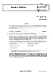
NOVA DARKROOM EQUIP ENT Operating Instructions for Nova Deep Tank Print Processors and Integral Wash Units Compiled by Steven Price Issue 6 ... .'YA SYSTEM I ,Unit 1A • Harris Road • Wedgnock Industrial Estate • Warwick • CV34 SJU ~_ _ _ _-1 Telephone: 01926 • 403090 (International: +44 1926403090) Fax: : 01926 • 499992 Welcome to the new breed of print processors ... The Nova System is a practical method of producing hand finished quality prints. Our range is designed to meet the needs of the process and make printing a pleasure not a chore. To enable you 10 oblain the best results from your new equipment, it is important that you read the instructions carefully before you proceed. REMEMBER All modern photographic materials are capable of excellent results. Changing from one manufacturer to another will not correct any problems relating to variables in technique or equipment. The only route to constant quality printing is to reduce these variables to a minimum. Small fluctuations in voltage, timing or temperature can cause large changes in image density and colour balance. Producing Colour prints can be as easy as Black and White providing you are in full control of every component. The following steps will assist you: 1) 2) 3) 4) Fit a voltage stabiliser to the enlarger. Time the exposure and process sequence accurately. Temperature control will be handled by your Nova Processor. Use one type of film, paper and chemicals until you are confident enough to experiment. With all Nova Processors it is important to begin by placing your new processor on a table/bench as near to your enlarger as possible, ensuring that the drain taps are easily accessible. 2 , ELECTRICAL CONNECTION This unit is titted with mains electrical thermostatic control equipment and as such must only be connected to the relevant electrical supply. Please refer to the electrical specification label on the rear of the plug-in Powerstat controller. It is strongly recommended that you utilise a mains supply that is protected bya Residual Current Device (RCD). These are sometimes already present in your mains fuse box. If not, similar devices can easily be purchased from any electrical supplier or good hardware store which enable you to plug the Powerstat direclly into it. Any part of the cable between the Powerstat controller and the processor forms an integral part of the heating system and carries vital sensor information. Under NO circumstances must the cable, or any inter connecting cable between heaters, be severed otherwise serious injury or product damage may result. The cable is double insulated and therefore does not require separate earthing 00 NOT SWITCH ON Initial preparation tor all processors WE RECOMMEND THAT YOU FILL YOUR PROCESSOR WITH WATER AND SET YOUR REQUIRED WORKING TEMPERATURE BEFORE MIXING ANY PROCESSING CHEMISTRY. 1) Locate water core filler holes (12mm diameter) on the top of your processor. Note: There is one filler hole on Tandem processors and two on all other processors. 2) All 10 x 8 Processors must have each water core filled to within 25mm from the top. All other sizes have water level bungs located I FIG.l at the rear of the unit (Fig. 1). Remove each bung and fill each water core until water trickles out of the hole. Replace the bungs. NOTE: It is advisable to add a spoonful of domestic bleach to the water cores so as to prevent the build upofalgae. CHECK YOUR WATER CORE LEVELS EVERY WEEK. Note: Preheated water can be used to acce/erate wann up time but never use water above 32'C (9CJ'F) as this may cause undesirab/e distoJtion within the processor. 3) When filling your processor for the first time, it is advised that you use water in the chemical slots until you have correctly set your chosen working temperature. This procedure also helps to rid the internal surfaces of any manufacturing dust which may be present. Note: If your processor has an integral wash included then turn to section 18 for information on connection before proceeeding, Remove the tubular slot lids, then fill all the slots (Fig.2) and water cores with solution, including any integral wash which may be part of your unit. You may proceed to switch on the processor. FIG.2 ~ WARNING: ALL CHEMICAL SLOTS AND WATER JACKETS MUST BE FILLED BEFORE YOU SWITCH THE PROCESSOR ON . FAllURE TO 00 SO MAY CAUSE UNDESIRABLE LOCAL DISTORTION, MAY BREAK THE GLASS HEATER TUBES AND WILL IN VA LIDATE YOUR GUARANTEE. NEVER POUR COLD WATER ONTO HOT HEATERS. SWITCH ON FIG.3 4) All the temperature markings on your Powerstat refer to the temperatures achieved in the water cores . Owing to the specific nature of all darkrooms and their varying environments, it will be necessary for you to set the required temperature using a ~ ~ • ~ L -_ _ _ _--' thermometer in the developer slot to 'calibrate' it to your darkroom. A differential exists where the water core temperature is always between 3"C-6"C higher than the developer slot, depending upon the size of the uni!. Once you establish the differential in your darkroom, this will act as a good guide for future temperature selections. SETTING THE TEMPERATURE Initially select the required working temperature on the Powerstat (allowing a few "C as mentioned above) and leave the processor to heat and stabilise for about 2 hours (i .e. when the developer temperature reaches a peak and stops fluctuating) . After the stabilisation period , check the temperature in the developer slot and adjust the controller, if necessary, to achieve the correct temperature . Again, allow further time for rising or falling and stabilisations before adjusting further. Once set, just turn on and off at the power supply when required . Accuracy will be maintained at 0.20"C. Note: In all units, (except Tandem Processors), there are two heater elements controlled by one thermostat. This may cause central inner slots to run at higher temperatures than the outer slots. This is a normal feature and can be compensated for by adjusting process times if necessary. 5) With your temperature set, switch off the processor and allow the whole unit to cool to room temperature and then empty the water from the chemical slots using the drain taps. Mix a sufficient quantity of each chemical for your particular size of processor. The table below shows the chemical capacities of each size . Size Approximate Chemical Capacity All 10 x 8 units 1 Litre/slot All 16 x 12 units 2 Litres/slot All 20 x 16 units 3.5 Litres/slot All 20 x 24 units 5.5 Litres/slot 3 To avoid any possible contamination , begin by filling the bleach fix slot first and the developer slot last. Each solution slot must be filled to 5mm above the top of the print when an agitation clip is suspended in the slot. With the drain taps facing you, you will find it easier to work from lett to right (i.e. developer far lett). Note: It is important that the slots are not filled higher than recommended otherwise bleach fix may be transferred into the developer. If this occurs, then the developer will be contaminated and unusable. Switch on the processor again and leave it to stand until it has reached the temperature wh ich you set previously. Note: Leaving the lids in place with the power switched on between printing sessions, causes a slight rise in temperature. Always remove lids 30mins before use to allow the unit to stabilise. IMPORTANT - UNDER NO CIRCUMSTANCES MUST THE PROCESSOR BE PHYSICALLY MOVED WHILST THE SLOTS ARE FILLED WITH CHEMICALS . ALWAYS DRAIN THE SLOTS FIRSTLY, OTHERWISE CONTAMINATION OR UNIT STRUCTURAL DAMAGE MAY RESULT. BEGINNING YOUR PRINTING SESSION OARKROOM CONOITIONS 6) Having exposed your print on the enlarger baseboard, take an ag:::.i_ta_t_io_n--=!==;-;=========~ clip and attach it to the print. r i I The diagram (Fig.4) shows a simple and comfortable method of holding the clip. 7) Present the back of the exposed print to the edge of the developer slot (Fig.5). 4 8) Raise the print until you feel it locate in the slot and then gently lower it into the chemical (Fig.6). 9) OEVELOPING Agitation must be carried out in agentie circular motion continuously for the first 30 seconds. Thereatter, agitation need only be done every 20 seconds throughout the rest of the development time. This should last approximately 5 seconds and complete the sequence by raising the print half out of the slot and then lowering back into place. Note: When producing small test prints, one may be tempted to make use of the increased space within the slot for agitation. It is advised that this should be avoided and that test prints be processed if"} arestricted area of the solution so as to simulate the same processing conditions as the final print. Failing to to this may give a false indication of filtration and development. 10) When your development time is complete. you must remove the print from the slot making use of the blade edge located on the top of the water cores (Fig.7) . By curving the print and scraping the back of the print on the blade, you will remove excess chemieals and minimise crossover contamination. FIG .7 ~ ~ ~ 11) STOPPING THE PRINT If your processor has a stop bath incorporated then locate the print in the slot and agitate for about 15 seconds. Having done this, remove the print as previously shown . Note: Lights may be switched on at this stage when printing from negatives. (; 12) BLEACHINGIFIXING Locate the slot and, without hesitation, agitate immediately for the first 30 seconds. Thereafter, agitate occasionally lor the rest of the bleach fix time. If you are using a processor without a stop bath, the period of time between removing the print from the developer and the first 30 seconds in the bleach fix is very crucial. The bleach fix will be acting as the stop bath and any hesitation in the agitation may give rise to uneven stopping of the image and thus cause streaking. Immediate and continuous agitation for the first 30 seconds will prevent any problem. 13)WASHING Wash your finished print in your usual apparatus ensuring that there are plenty 01 changes of water throughout the wash time. II your Nova processor has an integral wash incorporated or you have a 'Nova Vertical Washer' , then place the print in the slot and regulate the changes of water by way of the tap. (Refer to section 18 for information on connection). The recommended washing times with Nova wash un-its will vary depending upon the temperature of the water. Approximate wash times: Cold water (12°C) Warm water (30°C) Resin Coated 2 - 3 minutes 1 - 2 minutes Fibre based 30 minutes 20 minutes It is recommended that you replenish each of the chemicals after producing approximately 8-10 lull size prints from negatives or 6-8 prints Irom slides. These are only guide lines tor when replenishment should be carried out but the actual limes 10 replenish will depend on what your subject matter consisls 01 and how particular you are about the actual colour saturation of a prin!. It is recommended that you keep printing until you are no longer satisfied with the quality of I FIG.8 contrast or colour. Make use of the drain/replenishment taps on the front of your processor to remove the appropriate spent volume of solution (Fig.8). Top up with fresh stock solutions and allow the temperature to stabilise if you wish to continue printing (Fig.9). Recommended replenishment rates are as folIows, per print processed : Note: /t is possib/e to use your so/utions to _ -=""----_---' exhaustion without any rep/enishment, by increasing your process time sufficiently to achieve a good black. LI Remove the print from the slot and it is ready to be dried. 14) The Clip needs only a rinse in clean water and a light shake before re-use. 15) REPLENISHMENT Your Nova processor is designed to allow you to keep stock/working solutions in the unit whilst not in use . Replenishment should take place at the end ot a printing session and also during the session if your are doing a Iong print run. 10 x 8 16 x 12 20x 16 20x24 Prints from negatives RA4 Prints from negatives B&W/EP2 10ml 20ml 40ml BOml 15ml 35ml 65ml 140ml Prints from slides R3/11foChrome 35ml 70ml 140ml 2BOmi 5 END OF SESSION 16) Having finished your printing, all you have to do is replace the appropriate tubular lids to the top of each chemical slot (Fig .10) and then wipe clean the bl ades on the top of the unit. When wiping the tops, ensure that no bleach fix gels into the developer. CHECK LEVEL OF WATER CORES REGULARL Note: You will experience staining of the walls within the processor but this is permanent and will not affect your print quality, chemicals or performance ofyour print processor. Your Nova processor is now conveniently ready for your next printing session. CONNECTING YOUR INTEGRAL WASH MAINTENANCE 18) FOR ALL NOVA CLUBMATE AND NOVA CHROME-R PROCESSORS 17) On occasions depending on tank size and Irequency 01 use, it is necessary to clean out your processor. This is best done with the aid of Nova's specially formulated tank cleaner 'TARBUSTER' (code No ANTAR) . If unavailable, then you must use lots 01 running water and a bottle brush to clean the slot surfaces. It is quite acceptable to change Irom one process to anolher (ie Black & White 10 RA4, or RA4 10 IIloChrome and vice versal wilhout any problem , and all Ihal is required is a Ihorough rinsing 01 Ihe processor. If Ihe process slols are 10 be drained and the unit unused lor several weeks , it is advisable 10 clean oul Ihoroughly wilh waler so as 10 prevenl hardened sedimenl and crystallisalion lorming inside the slots. Below are guidelines lor chemical lile expeclancy in Ihe lank and when cleaning of the processor should take place. Chemicals 10 x 8 16 x 12 20 x 16 20x24 6 All Colour negative chemicals 1 - 2 months 3 - 4 months 6 - 8 months 10 -12 months All R3/111oChrome and El&W Chemieals 1 - 2 weeks 3 - 4 weeks 4 --6 weeks 4 - 6 weeks (; INPUT Obtain a length of flexible hose with an inside diameter of 12mm. Connect one end to your water supply. The other end should be fitted over the short piece of existing rubber pipe located at the rear of the unit near the base . This should be a tight fit. There is a NOVA Plumbing Inlet Kit available (code No ANVIK) which easily pushes over the in let tube of the washer. OUTPUT You will require a 25mm domestic waste pipe fitting , available from most plumbers' merchants or DIY stores . These should be push on fittings to reach your nearest suilable drain. There is a NOVA Universal Plumbing Outlet Kit available (code No ANUOK) which easily pushes over the outlet tube of the washer. IN OPERATION Turn on your supply and water will flow in a circular pattern up to the outlet. It may be necessary to use your input supply tap to restrict the flow dependent upon the pressure of your mains supply. Check for any leaks around the inleVoutlet pipes and all joints in the waste pipe. Note : Nova Chrome-R Processors will require TWO inlets and TWO outlets. Nova's Helpful Printing Tips ... Colour printing wi1h the Nova can be as uncomplicated as you wish but if you are looking for perfection and consistency in your results, try to apply as many of these tips as your circumstances allow. 1) ELiMINATE AS MAY VARIABLES AS POSSIBLE. a) Reduce voltage fluctuation to the enlarger with a voltage stabiliser. b) Choose one make of chemistry and continue to use it. c) Use one brand of paper. d) Filtration problems can be reduced if you use one type of film. e) Agitate test prints in exactly the same way as end prints. f) Try to avoid using developer to exhaustion . The replenishing method gives far greater consistency. 2) For best results in any tank processor, agitation should take place continuously for the first 30 seconds and then for at least 5 seconds every 20 seconds - or it can be continuous for the whole time. When developing any kind of sheet film in the uni1 (i.e. X ray film or Lith film), it is recommended that you agitate continuously throughout the wh oie process. 3) If possible, use theenlarger lens to control exposure, and use only one exposure time (e.g. 10 seconds), as differences in exposure time affect filtration. 4) When making test prints, ensure that the exposure is right before attempting to correct any colour bias. ~ 5) If the print has a blue haze, especially in the dar!< areas of the image ... a) Is the temperature too low? b) Are you agi1ating in the development stage sufficiently? c) Is the developer solution exhausted? 6) If the white areas of the print are pink ... a) Is the developer temperature too high? b) Is the process time in the development stage too long? c) Is your safelight. .. i) Too bright? ii) Too close to the wor!< area? 7) If streaks are visible in the light areas of the image .. . a) Are you agitating sufficiently in the bleach fix stage, especially during the first 15 seconds? b) Is your bleach fix solution exhausted? 8) If the internal textured surface pattern is present in the final print ... a) Insufficient agitation in the development stage. 9) If discolouration occurs around the area of the clip ... a) Are your solution slots filled too high? b) Have you thoroughly rinsed the clip before attaching to your next print? '10) A helpful Filtration Chart is on the back page ... why not pin it on your darkroom wall? 11) When printing from negatives, avoid the use of the Cyan filter. Correct filtration by way of using the Magenta and Yellow filters. Should you experience any problems in setting up or using our equipment, we would be only too pleased to offer assistance. 7 COLOUR CAST CORRECTION CHART NEGATIVE in the enlarger Add YELLOW Add MAGENTA COLOUR TRANSPARENCY CAST in the enlarger YELLOW MAGENTA .. Subtract YELLOW Subtract MAGENTA Subtract YELLOW & MAGENTA CYAN Subtract CYAN Subtract YELLOW BLUE Add YELLOW GREEN Subtract MAGENTA RED Add YELLOW & MAG ENT A Add MAGENTA Add CYAN r HAVING PROBLEMS wmt cc>LOUR ALlRATlON? nd VOll need a Nova RtngArOU A • 5Y5T1:M Pin this useful guide on your darkroom wall 1 1 1 1 1J .~ 1" 1 ~~ .1 1 11 1i I 1 I 1~ , 1! 1! 8, 1~ ' ! o NOVA DARKROOM EQUIPMENT Unit 1A • HaITis Road • Wedgnock Industrial Estate • Warwick • CV34 5JU Telephone : 01926·403090 . Fax : 01926·499992 I ~ 1! 1 I