1
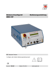
Operating Instructions
BMH-22i
Stud Welder
BMH-22i
2
BMH-22i
Operating Instructions
BMH-22i
Stud Welder
Serial number*
BMH-22i stud welder _________________________
Please enter the serial number here to have it immediately
available if you need service support.
Order No.
Code designation
Note
P01345
P0XXXX
BMH-22i
BMH-22i A
Standard device (mains connection 3 x 400 V)
Standard device (mains connection 3 x 400 V)
with automatic set for stud reload
Heinz Soyer Bolzenschweißtechnik GmbH
Etterschlag
Inninger Straße 14 - 82237 Wörthsee - Germany
Tel.: +49 8153 885-0 – Fax.: +49 8153 8030 - www.soyer.de
3
BMH-22i
Congratulations on purchasing the BMH-22i SOYER stud welder.
You have made an excellent choice. Your BMH-22i SOYER stud welder was specially
developed for the high-speed fastening of SOYER welding studs in compliance with
DIN EN ISO 13 918 on metallic, weldable workpieces.
Our devices have been tested with regard to safety requirements and correspond to the currently valid European and national guidelines. Proof of
conformity has been established and the manufacturer is in possession of the
corresponding documents.
FOR YOUR SAFETY
Read all of these operating instructions prior to start-up. Please
follow all safety precautions as well as all chapters of these
operating instructions before starting to weld. Non-compliance with
the safety precautions can result in serious personal injuries or
death.
SOYER® is a registered trade mark of Heinz Soyer Bolzenschweißtechnik GmbH.
It is prohibited to transmit or reprint this document, as well as to utilize or disclose its
contents, unless this has been expressly granted.
Non-compliance with this regulation is liable to compensation. All rights reserved,
particularly in the case of a patent grant or a GM registration.
We have verified that the contents of this pamphlet correspond to the hard- and
software described. Deviations, however, cannot be excluded so that we cannot
warrant for absolute compliance.
The illustrations contained in this instruction manual may vary in some details from
your product. This, however, has no influence on the handling of the machine.
The data in this documentation have been verified regularly and necessary corrections
will be incorporated in future impressions. Any suggestions for improvement will be
appreciated.
Date of issue:
January 02, 2006
Revision:
--------------© Heinz Soyer Bolzenschweißtechnik GmbH 2005 · All rights reserved
Printed in the Federal Republic of Germany
4
BMH-22i
Table of contents
1
Safety precautions.............................................................................................. 7
1.1
Description of reference signs in the operating instructions .......................................... 9
1.2
Staff qualification and training...................................................................................... 10
1.3
Dangers in the case of non-compliance with safety instructions................................. 10
1.4
Before starting to weld... .............................................................................................. 10
1.5
Working with the stud welding equipment ................................................................... 10
1.6
Inadmissible operating methods .................................................................................. 10
1.7
Stopping the stud welder ............................................................................................. 10
2
General............................................................................................................... 11
2.1
The following should be principally observed... ........................................................... 11
2.2
Intended purpose ......................................................................................................... 11
2.3
Marketing and service.................................................................................................. 11
2.4
2.4.1
2.4.2
Information on the documentation ............................................................................... 12
Information on operating instructions........................................................................... 12
Conduct in the case of malfunctions............................................................................ 12
3
Description of stud welder............................................................................... 13
3.1
Drawn arc stud welding technology ............................................................................. 13
3.2
3.2.1
3.2.2
Stud welding ................................................................................................................ 14
Drawn arc welding with shielding gas.......................................................................... 14
Drawn arc welding with ceramic ferrules ..................................................................... 14
3.3
3.3.1
3.3.2
Manual electric welding / TIG welding ......................................................................... 14
Manual electric welding (electrode welding) ................................................................ 15
TIG welding.................................................................................................................. 15
3.4
Construction of the BMH-22i stud welder .................................................................... 16
3.5
Technical data.............................................................................................................. 17
4
Installation of stud welder ............................................................................... 18
5
Start-up .............................................................................................................. 19
5.1
5.1.1
5.1.2
5.1.3
5.1.4
Front and rear view ...................................................................................................... 19
Operating elements...................................................................................................... 21
Display elements.......................................................................................................... 21
• LED display................................................................................................................ 21
Symbols ....................................................................................................................... 23
5.2
5.2.1
5.2.2
5.2.3
5.2.4
Preparation for start-up ................................................................................................ 24
Earth connection .......................................................................................................... 24
Connection of stud welding gun................................................................................... 25
Gas supply ................................................................................................................... 25
Power supply ............................................................................................................... 26
5.3
5.3.1
5.3.2
Adjustment of operation modes ................................................................................... 26
Starting the stud welder ............................................................................................... 26
Operation modes / parameters .................................................................................... 26
5.4
5.4.1
5.4.2
5.4.3
5.4.4
Special functions.......................................................................................................... 30
Special function "Erasing the working storage" ........................................................... 31
Special function "Display of operating counter"........................................................... 31
Special function "Selection of language / Display of software version number".......... 31
Special function "Setting the type of feeder and its functions" (option) ....................... 32
5
BMH-22i
5.4.5
6.1.1
6.1.2
6.1.3
Special function "Setting the feeder operation" (option) .............................................. 33
6
Operation ........................................................................................................... 35
Setting welding parameters for standard welding operation........................................ 35
Welding parameters for welding operation .................................................................. 38
Minimum sheet thickness when welding with drawn arc operation ............................. 38
6.2
6.2.1
6.2.2
Welding operation with shielding gas .......................................................................... 39
Preparation of gas supply ............................................................................................ 40
Instructions for welding with shielding gas .................................................................. 40
6.3
Welding operation with ceramic ferrules..................................................................... 41
6.3.1
Instructions for welding with ceramic ferrules.............................................................. 41
7
Quality control (stud welding) ......................................................................... 43
7.1
General ........................................................................................................................ 43
7.2
Demands on the company........................................................................................... 43
7.3
7.3.1
7.3.2
7.3.3
7.3.4
Test execution.............................................................................................................. 43
Production of samples ................................................................................................. 43
Visual inspection .......................................................................................................... 44
Bend test...................................................................................................................... 45
Tensile test................................................................................................................... 45
8
Maintenance ...................................................................................................... 46
8.1
Important instructions................................................................................................... 46
8.2
8.3
8.3.1
8.4
Important instructions for all service works.................................................................. 46
Cleaning....................................................................................................................... 46
Detergents for cleaning the housing ............................................................................ 46
Replacement of components ....................................................................................... 46
9
Troubleshooting ............................................................................................... 47
9.1
Malfunctions................................................................................................................. 48
10 Transport and storage...................................................................................... 51
11 Terms of warranty............................................................................................. 51
12 List of standards and guidelines .................................................................... 52
Appendix A /
Adjustment of short-cycle drawn arc welding guns
6
Appendix A
BMH-22i
1 Safety precautions
These safety precautions are for your safety.
General safety instructions
Become trained and read and follow all safety precautions listed below as well as all
chapters of this manual before starting to weld.
Non-compliance with the safety precautions can result in personal injuries or
death.
Only qualified persons are allowed to install, operate and maintain the equipment.
Keep away children and juveniles under the age of 16 years from the equipment.
WARNING
It is prohibited to open the stud welder.
The service personnel are required to meet special qualifications.
Our after-sales service has adequately trained personnel, suitable service equipment
and the means to carry out all necessary works.
Warning of electromagnetic fields
Keep sufficient distance from electronic devices. When stud welding, highly intensive
electromagnetic fields are created which may permanently damage these devices (e.g.
television sets, airbags).
Ensure that the welding equipment is not operated near electronically sensitive lifesupporting equipment, such as in intensive care units in hospitals.
Persons with pacemakers must neither operate the stud welding equipment nor stay
near it while it is running.
Electric shock can cause death
Prevent electric shock by insulating your body from work and ground. Stand on dry
insulating material such as rubber mats and wear rubber soled shoes.
Be sure power source is properly connected to the ground system of the power supply.
Inspect all cables including power cord for damage or bare wiring. Immediately replace
damaged or worn cables.
Always ensure the correct supply voltage in accordance with the data plate. Never
connect the stud welder to a power supply network with incorrect supply voltage.
Always disconnect the mains cable from the mains supply before starting any cleaning
works. Only trained and appropriately qualified personnel are allowed to carry out works
at the electric mains supply and welding system.
Do not touch live electrical parts with bare hand. Wear dry, hole-free insulating gloves.
Do not wear rings, watches or electrically conductive jewellery.
Keep the work area, studs, stud holders, guns, cables, power source as well as your
clothes dry.
7
BMH-22i
Fumes and gases can cause damage to your health
Fumes and suspended matters may be generated during welding. Beware of fumes
detrimental to health, particularly when using surface treated materials. If possible, only
weld in rooms which are higher than 3 m. Please also observe the safety regulations
applicable for your country.
Do not breathe fumes and gases. Use adequate ventilation in the work area to remove
fumes and gases (e.g. ventilating fan). Exhaust welding fumes, if necessary.
Welding can cause fire and explosions
Welding sparks and heat from flames and arcs can cause fires. Have a portable fire
extinguisher handy for immediate use. Be sure you are trained for properly using it.
When welding, do not wear clothes soiled with easily combustible substances such as
oil, grease and paraffin oil etc.
Comply with the fire regulations and do not weld, for instance, in hazardous locations.
Pay attention to flammable objects at the welding place. All flammable materials and
liquids, such as oil, fuel, etc. must be removed prior to the start of work.
Electronic equipment (e.g. airbags) and the use of explosive substances for fuel supply
require further safety precautions when carrying out welding operations on cars.
Appropriate information can be obtained from the trade associations or the car
manufacturers.
Skin and eye protection
Arc rays and welding spatters can injure eyes and skin.
Wear safety glasses with side shields and protective goggles with correct shade of filter
to protect your eyes from welding spatters and flashes of light that are generated during
the welding process.
Wear gauntlet gloves made of leather and non-combustible closed working clothes such
as heavy long-sleeve shirt, cuffless pants and high boots.
Wear a leather apron to protect your clothes from welding spatters.
Keep sleeves and collars buttoned and remove open pockets from the front side of your
clothing.
We recommend using ear protection. Some welding and working processes may
generate loud noises.
Moving parts can cause injury
Beware of moving parts such as fans. Keep hair, hands, loose clothing and any tools
away from the air apertures.
8
BMH-22i
1.1
Description of reference signs in the operating instructions
The non-observance of safety instructions such as pictographs and warning words can cause damage
to persons. The safety instructions of this manual describe the following:
Safety instructions
Danger!
Immediate hazards which could result in serious personal injuries or loss of
life.
Warning!
Potential hazards which could result in serious personal injuries or loss of
life.
Caution!
Potential hazards which could result in minor personal injuries.
Caution!
Warning of damage
Note!
Potential detrimental situation which may cause damage to the product or
to an object surrounding it.
Important!
Instructions for application and other useful information facilitating the
proper use of the product.
Safety symbols
The following pictographs for warnings, bans and decrees are used in this manual:
Ban for persons with
pacemakers
Ban (only in combination
with an additional safety
symbol)
Do not touch
Housing is currentcarrying
Fire extinguisher
Warning of a danger
spot
Warning of dangerous
electric voltage
Warning of
electromagnetic field
Warning of moving
parts
General ban (only in
combination with an
additional safety
symbol)
Warning of inflammable
substances
Warning of explosive
substances
Eye protection required
Protective clothing
required
Ear protection
required
)
Protective gloves
required
General instructions are marked with the hand symbol.
9
BMH-22i
1.2
Staff qualification and training
The staff responsible for operation, maintenance, inspection and assembly must have the respective
qualification for carrying out these works. Field of responsibility, competence and the supervision of
staff have to be exactly regulated by the user. If your personnel do not have the necessary knowledge,
they have to be trained and instructed. If necessary, this can be done by the supplier on behalf of the
user. Furthermore, the user must ensure that the contents of the operating instructions are fully
understood by the staff.
The society of welding institutes (GSI: Gesellschaft der Schweißtechnischen Institute mbH) offers the
appropriate training courses for your personnel.
For information on branches, please refer to website http://www.dvs-ev.de.
1.3
Dangers in the case of non-compliance with safety instructions
The non-compliance with safety instructions may not only endanger persons, but also the equipment
and its environment. Any non-compliance with safety instructions may result in a complete loss of
damage claims.
Non-compliance with safety instructions may have the following consequences:
• Failure of important system functions
• Failure of prescribed methods for maintenance
• Danger of persons through electric, mechanic, thermal and acoustic influences
1.4
Before starting to weld...
• Check the state of all cables and cable connections before starting to weld.
• Immediately replace defective cables and cable connections.
• Ensure that the air apertures of the housing are not covered. Heat accumulation may damage the
stud welding device.
1.5
Working with the stud welding equipment
• Comply with all accident prevention regulations which apply to the operation of your stud welding
device.
If an accident happens,
• switch off the welding device and disconnect it from the mains supply
• call a doctor.
1.6 Inadmissible operating methods
Limit values
Working safety of the stud welding equipment supplied can only be guaranteed when the system is
used in accordance with its purpose. The limit values indicated in the chapter “Technical data” must
never be exceeded.
1.7
Stopping the stud welder
• Press the red OFF button "0".
• Disconnect the mains plug from the socket.
• Disconnect
- the control cable
- the welding cable
- the earth cables
- possibly existing gas supply and compressed-air supply
from the stud welder.
• Roll up the cables without buckling them.
• Prevent the stud welder being operated by unauthorized personnel.
10
BMH-22i
• Check welding cable and connections of the stud welder for damage such as burn-off, mechanical
wear etc. and have damaged parts replaced by the SOYER customer service.
2 General
2.1
The following should be principally observed...
With this stud welder you have purchased a product which
• is state-of-the-art technology
• fully complies with the current safety requirements and
• enables successful working.
Before installing the stud welder, please observe the following:
• Store the operating instructions in a place accessible to every operator.
• Ensure that the respective operator has read and understood the operating instructions prior to startup. Each operator should confirm this per signature.
• Prevent the stud welder being operated by unauthorized personnel.
• Only trained personnel may operate the stud welder.
• Call a doctor in case of an accident.
2.2
Intended purpose
The BMH-22i SOYER stud welder for drawn arc welding allows SOYER threaded studs as per DIN EN
ISO 13918 and ranging from M8 – M24 RD (MR) or Ø 8 – 22 mm (studs, shear connectors, concrete
anchors) made of plain, stainless and heat-resistant steel to be welded on different workpieces
(sheets, tubes, steel girders etc.).
Usually round pins with or without thread are welded. You may also weld fasteners with different
cross-sectional shapes. For this purpose, however, special stud holders and ceramic ferrules or gas
shrouds are required.
With the BMH-22i SOYER stud welder it is also possible to weld studs of other metallic materials than
steel. It is, however, necessary to first carry out experimental welds and to inspect them.
Manual electric welding (electrode welding) and TIG welding are also possible to a limited extent.
2.3
Marketing and service
If you have any questions regarding the operation of the BMH-22i stud welder, retrofits for special
applications or if you require service, please contact your responsible service office or the following
address:
Heinz Soyer Bolzenschweißtechnik GmbH
Etterschlag
Inninger Straße 14
D-82237 Wörthsee
Telephone +49 8153-885-0
Telefax +49 8153-8030
www.soyer.de
[email protected]
11
BMH-22i
2.4
Information on the documentation
The following operating instructions are supplied with the BMH-22i stud welder:
• Operating instructions for BMH-22i stud welder
2.4.1
Order no. P00233
Information on operating instructions
Legal relationship
We draw your attention to the fact that the contents of these operating instructions are neither part of
any former or existing arrangement, pledge or legal relationship nor are designed for modifying the
latter. All obligations of Heinz Soyer Bolzenschweißtechnik GmbH result from the respective
contract of purchase which also comprises the complete and generally valid warranties. These
contractual warranty terms are neither extended nor restricted by the implementation of these
operating instructions.
CAUTION
Do not carry out any actions on the stud welding equipment without specifically
knowing the operating instructions or the respective part. Ensure that only qualified
personnel familiar with the operating instructions and the necessary technical
activities (training!) operate the system.
2.4.2
Conduct in the case of malfunctions
If malfunctions occur, first try to detect and eliminate the causes according to the "Troubleshooting" list
in chapter 9 of these operating instructions. In all other cases, please contact our service department.
If you require our service, please make sure that you supply us with the following information:
• Customer number
• Serial number
• Stud and workpiece material
• Product designation / options
• Year of construction
• Stud dimensions
This information will help us both to save time and unnecessary costs, e.g. caused by delivering the
wrong spare parts.
12
BMH-22i
3 Description of stud welder
3.1
Drawn arc stud welding technology
Illustration 1: Drawn arc stud welding technology
The BMH-22i SOYER stud welder runs according to the principle of drawn arc stud welding.
A D.C. power supply with inverter technology provides the welding current. For detailed information,
please refer to the following regulations:
• DIN EN ISO 14555, "Arc welding of metallic materials"
• DVS Information Sheet 0902, "Drawn arc stud welding"
1. When welding, the stud is positioned on the workpiece.
2. The preweld current is ignited and the stud is lifted off the workpiece.
3. The subsequent ignition of the main current creates a molten pool between stud and
workpiece.
4. The stud immerses in the liquid molten pool and the material solidifies.
This method allows manual, semi-automatic and fully automatic inseparable welding of threaded
studs, pins, tapped studs, insulating pins, special studs and many other fasteners made of steel, CrNi
steel, heat-and acid-resisting steel with the workpieces. Conditionally it is also possible to weld nickel
and titanium depending on the respective requirements. Standard studs for drawn arc and capacitor
discharge welding in compliance with DIN EN ISO 13918 can be welded without requiring any
auxiliary aids. The application of shielding gas or ceramic ferrules is recommended for studs with a
diameter of more than 6 mm to prevent pore formation and to optimise the formation of bulges.
The standard BMH-22i stud welder is suitable for operation with shielding gas and ceramic ferrules. A
D.C. power supply with inverter technology provides the welding current.
IMPORTANT INFORMATION
Ensure that the surface is electroconductive.
Grind hot galvanized parts.
The following welding methods are possible when using the BMH-22i SOYER stud welder:
• Short-cycle drawn arc stud welding without shielding gas and ceramic ferrules
• Drawn arc stud welding using ceramic ferrules as auxiliary aid
• Drawn arc stud welding using shielding gas as auxiliary aid
• Manual electric welding (electrode welding)
• TIG welding
13
BMH-22i
3.2
Stud welding
The PH-5L stud welding gun with control cable and shielding gas equipment is the standard gun to be
connected to the BMH-22i stud welder. These operating instructions only refer to the BMH-22i stud
welder.
For information regarding the stud welding guns to be used and their setting, please refer to the
respective operating instructions.
3.2.1
Drawn arc welding with shielding gas
With this method, a gas mixture containing 82% of Argon and 18% of CO2 (e.g. Corgon®18*) is used as
auxiliary aid.
This shielding gas protects the welding point from the atmosphere and simultaneously supports the
weld pool. Moreover, it ensures a concave fillet weld upset formation with a blank metallic surface,
thus reducing the risk of corrosion and obtaining an improved dynamic behaviour of the welded joint.
An accurate bulging, to scale or in a calibrated or reproducible type, is not possible when welding with
shielding gas without using any auxiliary aid. Stud welding with shielding gas can be carried out at
much shorter intervals as no ceramic ferrules have to be fitted and removed in each welding process.
*) Corgon®18 is a gas mixture of Linde AG in D-82049 Höllriegelskreuth
R
3.2.2
Drawn arc welding with ceramic ferrules
The ceramic ferrule fulfils the following functions:
• It centres the electric arc.
• It protects the welding point from the atmosphere.
• It ensures the exact formation of the weld upset.
• It prevents too rapid cooling of the weld pool.
• It partially protects against spraying sparks.
To ensure a perfect and accurate weld upset, each stud requires a ceramic ferrule matching its
diameter and shape. After every welding process, the ceramic ferrule must be knocked down and
replaced by a new one.
Usually this method allows you to weld in any position.
IMPORTANT INFORMATION
Ensure ceramic ferrules are absolutely dry.
3.3
Manual electric welding / TIG welding
Instructions on application:
These operating instructions only describe the function "stud welding".
Instructions on manual electric welding / TIG welding can be obtained from the respective
manufacturers of the necessary accessories.
14
BMH-22i
Table for electrical characteristic values as per DIN EN 60974-1
8)
6)
______
-----7)
10)
40 A / 21.6 V up to 300 A / 32 V
11)
11b)
X
9)
12)
U0 = 85 V
13)
12b)
I2
Field 8
Field 9
Field 10
Field 11
Field 12
Field 13
Field 11b,c
Field 12b,c
Field 13b,c
3.3.1
100 %
12c)
300 A
13b)
U2
Field 6
Field 7
11c)
60 %
200 A
13)
32 V
28 V
Graphical symbol for the welding process “Covered-Electrode Manual Arc Welding"
Symbol for welding current sources which are suitable for welding in an environment
of increased electrical danger
Symbol for direct current
Rated value of open-circuit voltage in volt
Lowest and highest power range
Symbol for operating time
Symbol for rated value of welding current
Symbol for standardized working voltage
Value of operating time in %
Rated value of welding current in ampere
Value of standardized working voltage in volt
Manual electric welding (electrode welding)
"Electrode welding" allows simple welding works with covered electrodes (electrode holders are not
included in delivery)
Please pay attention to the following:
Stud welding technology necessitates that the electrode holder is connected to the negative pole.
Polarity may, however, be reversed by changing the plug-in connection of the earth and welding
cables. Two adapter cables are necessary for doing so (special accessories).
The welding current is adjustable from 80A up to 300A in 20A steps.
The welding current has to be set depending on the electrode diameter and the welding task.
Approx. 40A for each mm diameter of the electrode may serve as a standard value for the current
adjustment.
CAUTION
During electrode welding, the connecting socket "welding cable" and the connecting
plug "earth cable" are always live.
The open-circuit voltage has always a direct voltage of approx. 85 V!
3.3.2
TIG welding
TIG welding allows simple welding works using a TIG welding torch (welding torch is not included in
delivery).
Please pay attention to the following:
Stud welding technology necessitates that the electrode holder is connected to the negative pole.
Polarity may, however, be reversed by changing the plug-in connection of the earth and welding
cables. Two adapter cables are necessary for doing so (special accessories).
Only direct voltage (DC operation) is available as welding current. It is not possible to change over to
alternating voltage.
The current may be adjusted between 80A and 200A in 20A steps.
15
BMH-22i
Gas and welding current are switched on by pressing the switch of the torch. Keep pressing the switch
during the welding process. Gas and current are switched off when you stop pressing the switch.
NOTE
Do not press the switch of the torch too long. There is no optional torch cooling
available.
3.4
Construction of the BMH-22i stud welder
The BMH-22i stud welder has a handy, compact and robust design.
The carrying handles on the top of the housing allow easy transport so that the stud welder can be
used at different work places.
16
BMH-22i
3.5
Technical data
Designation
Welding process
Welding range
BMH-22i
Drawn arc stud welding (DS)
Electrode welding rectifier
SOYER threaded studs, DIN EN ISO 13918 from
M8 – M24 RD (MR) or Ø 8 – 22 mm
Material
Steel, stainless steel and heat-resistant steel
Power source
Inverter technology
Welding current
300 up to 2000 A (stud welding)
80 up to 300 A (electrode welding)
80 up to 200 A (TIG welding)
Welding time
3 up to 1000 ms (only with operation mode "stud welding")
Welding sequence
up to 50 studs/min. depending on the respective stud diameter
Standard gun
PH-5L stud welding gun
Power supply
CEE 63 A (3P + protective earth conductor)
3 x 400 V 50/60 Hz +10% -15%
E-continuous current
2 A / phase
E-continuous power
1400 VA
E-maximum current
180A / phase with 3 x 400 V (short-time operation)
Open-circuit voltage
85 V / DC (direct voltage)
System of protection
IP21
Interfaces
(optional automatic set)
Feeder interface: 15-pole socket (option)
CNC interface:
9-pole socket (option)
RS 232 interface: 9-pin plug (option)
Compressed air supply
max. 6 bar (compressed air only with optional automatic set)
Shielding gas supply
max. 4 – 5 l/min.
Dimensions
560 x 420x 650 (w x h x d)
Weight*
70 kg
Colour
RAL 5009 azure
Subject to technical changes
*Slight deviations are possible depending on accessories.
WARNING
The “S” symbol is the symbol for welding current sources permitted for operation with
increased electrical danger. The “S” symbol on our stud welders refers exclusively to
the welding current circuit and not to the complete stud welder.
17
BMH-22i
4 Installation of stud welder
The top of the BMH-22i stud welder is equipped with two carrying handles.
CAUTION
The carrying handles are intended for transport by hand only. Never pull ropes through
these handles to lift the stud welder by means of a crane to the installation site. The
stud welder would become instable and might tilt from its original position. As a result
the handles could rip and the system would fall on the ground.
• Only install the stud welder on an even surface. The anti-vibration pads located on the bottom of the
welding equipment guarantee its anti-skid position and serve as vibration dampers.
• Although the stud welder is resistant to environmental influences, it should be protected against
dampness and dust.
• Please pay particular attention to the bearing strength of the workshop furniture and ensure a safe
and stable position of the welding equipment.
• Make sure there is sufficient free space around the air apertures, otherwise the excess temperature
safety mechanism will respond and interrupt the welding process. This state, represented as "Stud
welder not operative", is shown alternately with the current operation mode on the display.
Only when this information is no longer shown on the display, is it possible to continue the welding
operation.
• Install the stud welder close to the welding location.
• Ensure correct connected loads for electrical connections (see type plate).
)
The stud welder has a four-core connecting cable: 3 phases + protective earth conductor.
Please also refer to chapter 3.5, Technical Data.
Make sure mains socket and welding system are properly grounded.
• Please observe that additional extension cables cause a voltage drop, possibly leading to system
disturbances.
• Ensure sufficient ventilation of the working room when operating the welding system.
NOTE
The housing of BMH-22i stud welder corresponds to safety class IP 21. Please observe
that this system of protection is not suitable for being operated or transported in the rain.
CAUTION
When welding with shielding gas, make sure that the gas cylinder is installed safely and
vertically in its admissible, accident-proof installation device. It must not be installed in a
horizontal position since the gas cylinder connection and/or manometer could be easily
damaged.
18
BMH-22i
5 Start-up
5.1
Front and rear view
Front view of BMH-22i stud welder
1
2
3
4
5
6
• OFF switch to turn the stud welder off
• Signal lamp (operation mode)
• ON switch to turn the stud welder on
• LCD display
• LED displays for function control
• Function keys for setting the welding parameters
7
8
• Air function "forward"
(option)
• Air function "backward"
(option)
Connection for welding guns or heads with automatic stud feed
• Control cable connection
• Welding cable socket
The control cable connection and the welding cable socket serve to connect the stud welding
guns or heads to the stud welder.
• Gas connection socket
Before welding with shielding gas, connect the gas hose of the welding gun or head to the gas
connection socket.
• Earth cable connectors
The earth cable connectors serve to connect the earth clamps to the stud welder.
9
10
11
12
19
BMH-22i
Rear view of BMH-22i stud welder
13
14
15
16
17
18
19
20
21
22
23
20
9-pole connection for external program selection (option)
This interface serves to be connected with an external control system for controlling
the welding parameters.
Danger sign
15-pole connecting socket / Feeder interface (option)
The feeder interface serves to connect the feeder control to the stud welding device.
9-pole connecting socket / CNC interface (option)
The CNC interface serves to be connected with an external control system for
controlling the stud welding process.
9-pin connector, interface RS 232 (option)
This interface serves to be connected with an external control system.
Safety label
Type plate
Connection for STG-1 control device (option)
This connection serves to connect the STG-1 control device to the stud welder.
Shielding gas connector
This connection serves to supply the stud welder with gas by means of a pressure
regulator. The admissible gas flow value ranges between a maximum of 4 and 5 l/min.
Compressed-air supply connection (option)
This connection serves to supply the stud welder with compressed air and to connect
the compressed air leads of the feeder control to the stud welder. The admissible
supply pressure amounts to a maximum of 7bar.
Mains cable
The mains cable is a four-core (3P + PE), highly flexible connecting cable for
connecting the stud welder to the mains supply.
BMH-22i
5.1.1
Operating elements
• On/Off switch
Turn on/off switch to the "I” position to switch the stud welder on. The signal lamp shows that the stud
welder is operative.
Turn on/off switch to the "0“ position to switch the stud welder off.
• Function keys for setting the welding parameters
R
6.1
6.2
Function key “arrow up”
Function key “arrow down”
6.3
6.4
Function key “arrow left”
Function key “arrow right”
• Function keys "arrow up/down”
Modification of selected parameters (flashing symbol in display)
• Function keys "arrow left/right"
Selection of parameters to be modified (shifting of the flashing symbol to the left or right).
5.1.2
Display elements
• LED displays
5.1
5.2
5.3
5.4
LED “Stud on Workpiece”
LED “Release”
LED “Gas Valve Open”
LED “Lift”
5.5
5.6
5.7
5.8
LED “Main Current”
LED “Final Contact”
LED (no function)
LED (no function)
R
5.1.3
• LED display
The first line of the display shows the designation of the parameters to be set. The second line shows
the set value. When the parameter designation is flashing, you may change its value by using the
keyboard.
21
BMH-22i
Explanation of displayed operation modes:
• MODE
Operation mode set. It is possible to set six different operation modes:
1- OP = Operating state which must be set for normal welding operation.
2- PRE = Preweld current test
3- LIFT = Lift test
4- GAS = Gas test
5- ELECTRODE WELDING
6- TIG WELDING
Explanation of displayed parameters:
• PG (program)
The programs 1 - 30 are available for the user. The welding parameters for the respective welding
task can be determined and saved as user program in the programs 1 - 30.
• MC
Main current. Value set between 300 and 2000 ampere (operation mode “Stud Welding”).
• MCT
Main current time. Period of time set between 3 and 1000 milliseconds.
• PCT
Preweld current time. Period of time set between 40 and 1000 milliseconds.
• GPT
Gas preflow time. Period of time set between 0 and 9900 milliseconds during which the shielding gas
valve is open before welding and remains open after welding. Set "0" when welding without shielding
gas.
• RLT
Reload time. Period of time set between 0 and 9900 milliseconds during which the blow air valve
remains open to allow stud feed from the universal feeder to the welding gun/welding head. Set “0” to
switch off the automatic reload.
22
BMH-22i
5.1.4
Symbols
Symbol
Designation
Electrical energy
LED "Stud
on Workpiece"
Function
On/Off switch for turning the stud welder on and
off.
LED lights up when earth terminal of stud welder
is connected and stud touches the workpiece.
LED “Release"
LED lights up when pressing release switch of
welding gun or welding head.
LED "Gas valve
open"
LED lights up with shielding gas valve being open.
LED "Lift"
LED "Main current"
LED "Final contact"
LED lights up with lifting magnet of welding gun
being activated.
LED lights up when main current is supplied.
LED lights up after welding, with release switch
being pressed.
LED lights up when stud welder is operated by
remote control via the serial interface (RS232) (not
yet in use).
Function key "Arrow Upward alteration of the operation mode and the
up"
parameters selected (represented blinking in the
display)
Function key "Arrow Downward alteration of the operation mode and
down"
the parameters selected (represented blinking in
the display)
Function key "Arrow
Selection of parameters to be changed
left"
(relocation of blinking symbol to the left)
LED "External“
Function key "Arrow
Selection of parameters to be changed
right"
(relocation of blinking symbol to the right)
Air function
"forward"
Air function
"backward"
Gas supply
Air supply for stud welding gun/welding head with
automatic operation (optional equipment).
Air supply for stud welding gun/welding head with
automatic operation (optional equipment).
Gas supply for welding gun/welding head, coupler
socket KD - 1/4.
Earth
Marks earth cable connector to be connected with
earth cable.
Gun
Marks control and welding cable sockets to be
connected with welding gun.
23
BMH-22i
5.2
Preparation for start-up
Connect the stud welding gun and earth cables to the stud welder prior to start-up.
5.2.1
Earth connection
• Attach earth cable to earth cable connectors and lock by turning to the right until stop.
• Attach earth clamps to workpiece.
)
Ensure optimum contact with workpiece. Owing to the high welding current, an
unbalanced current distribution may cause a magnet blow effect on the arc, i.e. the
arc for welding the stud is asymmetrical. This is shown by an irregular course of the
weld upset on the side of the stud. The welding results are unsatisfactory and not
reproducible.
For this reason, you should attach the earth clamps to the workpiece in such a manner that the
welding gun is positioned as close as possible to the centre of the connecting route of both earth
clamps. This guarantees a current distribution around the stud that is balanced to the largest possible
extent and satisfactory welding results.
Difficult areas are welds on the edge of the workpiece or considerable differences in material
thickness, i.e. the material thickness varies by a few millimetres or additional material is welded or
riveted to the metal. This also includes stud welding on profile sections.
To ensure good welding results, carry out several test welds under different conditions. For example,
simply change the position of the earth clamps or turn the welding gun.
You may determine the symmetry and quality of the arc during the preweld current test and then
optimise them by combining earth connection and gun position accordingly.
)
Please ensure that the contact areas of the earth clamps are always kept clean and
do not oxidize, otherwise high transition resistances could occur that may result in a
considerable reduction of the rated welding current.
)
In addition, make sure that the earth clamps are clamped securely to the workpiece
and the earth cables as well as the gun cable are securely connected to the stud
welder. This prevents high transition resistances and arc losses on the clamps or
plug-in connections which in turn would result in poor welds.
24
BMH-22i
Examples for various earth connections and possible effects:
Balanced earth connection
Ideal condition: The stud is located in
the centre of both earth connections.
Unbalanced earth connection
Arc is deflected to the side where there
is less current density.
Additional masses disturb arc
symmetry.
5.2.2
Connection of stud welding gun
• Connect welding cable of welding gun to the welding cable socket and lock it by turning to the right
until stop.
• Insert control cable into control cable connection and tighten with sleeve nut.
• Please refer to the information given in the operating instructions for the welding guns.
5.2.3
Gas supply
When welding with shielding gas, provide the following connections:
• Insert gas supply hose's coupler plug of the welding gun into the gas supply socket of the stud
welder.
• Connect the gas hose of the pressure reducing valve (pressure reducing valve not included in
delivery) to the shielding gas connector at the rear side of the stud welder.
25
BMH-22i
5.2.4
Power supply
• Compare the power data (supply voltage / current consumption) on the type plate with the data
(supply voltage / fuse protection) of your power supply network.
)
Always ensure the correct supply voltage in accordance with the type plate. Never
connect the stud welding device to a power supply network with incorrect supply
voltage.
• Connect mains cable to power supply using the CEE plug:
DANGER
Only connect stud welder to approved CEE sockets.
Standard connection = 3 x 400 V + protective earth conductor, 63A-CEE. If need be,
have an expert in electrics check if the socket is earthed.
5.3
5.3.1
Adjustment of operation modes
Starting the stud welder
After switching the stud welder on, the 8 LED lamps light up for a short period. The stud welder carries
out a self test which is shown on the LED display.
The stud welder is locked during the self test and it is impossible to operate it or to enter data.
After the self test has been carried out successfully, the stud welder automatically sets the parameters
which were last set.
5.3.2
Operation modes / parameters
Press the function key "arrow right" or “arrow left" (3 or 4) to select the parameters. Only the
parameter designation which is flashing on the display can be set by means of the function keys (1 or
2).
The different operation modes possible have already been briefly described.
26
BMH-22i
5.3.2.1
Operation mode "OP" (operating state)
The operation mode "OP" allows normal welding operation with the welding parameters set.
• Use the function key "arrow up" or "arrow down" (1 or 2) to set operation mode "OP".
5.3.2.2
Operation mode "PRE" (preweld current test)
The adjustment "PRE" (preweld current test) enables you to carry out welds by means of the set
parameters without application of main current and serves to control the gun or head adjustment and
to test performance. During this operation mode, an arc is generated with low current when the gun or
welding head is positioned on the closed circuit (workpiece connected with earth) and the gun switch
is pressed (or when a signal is given via the interface). This is helpful to check the symmetry of the arc
or whether preweld current is flowing.
CAUTION
Protective goggles are required to carry out this test. Please also refer to the safety
instructions.
• Use the function key “arrow up“ or "arrow down" (1 or 2) to set operation mode "PRE".
5.3.2.3
Operation mode "LIFT" (lift test)
This operation mode enables you to adjust and check the lift of the gun or welding head. For further
information, please refer to the operating instructions of the welding gun or welding head.
• Use the function key “arrow up“ or "arrow down" (1 or 2) to set operation mode "LIFT".
27
BMH-22i
MODE
LIFT
Test lift with trigger
Drop time:
mS
1 or 2
3 or 4
KZ.2008.E
• Insert a stud into the gun or welding head.
• Check the immersion depth of the stud and/or set it according to the operating instructions of the
welding gun or welding head.
CAUTION
Ensure once again that the operation mode is set to "LIFT" and comply with the
safety instructions.
• Position gun or welding head on workpiece. The LED "Stud on workpiece" lights up.
• Actuate the trigger of the gun or the welding head or give a triggering signal via the CNC
interface. The stud is lifted off the workpiece as long as the triggering signal is there. After a
maximum of 4 seconds, however, the lift test will be interrupted to protect the magnet. There is no
welding current during this period of time.
If necessary, check and correct the height of lift according to the prescribed standard values for the
welding gun or welding head (please refer to the table for welding parameters in chapter 6.1.2).
R
If the lift test is carried out on a workpiece which is connected to the earth connection of the stud
welder, the drop time will be shown in milliseconds on the display. If the workpiece is not connected to
the earth connection, "no ground" appears on the display.
)
28
Do not activate the release too often in short intervals, as this would cause the thermo
safety mechanism protecting the lifting magnet to react and the current supply for the
magnet to be interrupted. This condition is displayed as follows:
BMH-22i
5.3.2.4
Operation mode "GAS" (gas test)
This operation mode checks whether the shielding gas flows through the gas shroud of the welding
gun or welding head. As long as a triggering signal is there, shielding gas flows out of the gas shroud
on the welding gun or welding head. This enables you to rinse the gas lines with shielding gas before
starting to weld.
• Select the operation mode "GAS" with the function key "arrow up" or "arrow down" (1 or 2).
• Connect gas supply
• The gas valve may be activated by
- the trigger of the welding gun or welding head
- an active start signal at the CNC interface
5.3.2.5
Operation mode "Electrode welding"
In the operation mode "Electrode welding" the stud welder works like a welding rectifier.
CAUTION
In this operation mode, an open-circuit voltage of about 80V (DC voltage) is always
applied to the terminals!
• Use the function key "arrow up" or "arrow down" (1 or 2) to set operation mode "ELECTRODE
WELDING".
29
BMH-22i
Use the function key "arrow right" (4) to set the welding current.
• Use the function key "arrow up" or "arrow down" (1 or 2) to set the desired current intensity.
5.3.2.6
Operation mode "TIG WELDING"
In this operation mode the stud welder works as a TIG welding device.
Gas and welding current flow when pressing the key on the burner.
• Use the function key "arrow up" or "arrow down" (1 or 2) to set operation mode "TIG WELDING".
Use the function key "arrow right" (4) to set the welding current.
• Use the function key "arrow up" or "arrow down" (1 or 2) to set the desired current intensity.
5.4
Special functions
With the stud welder BMH-22i you can call additional special functions:
)
Start dealing with the special functions when you are familiar with the basic
functions of the stud welder.
The stud welder must be turned off when calling special functions. In order to call the respective
special function you have to press certain function key combinations and keep them pressed when
starting the stud welder. Turn off the stud welder by means of the on/off switch to terminate the special
functions.
30
BMH-22i
After this, the stud welder can be restarted.
5.4.1
Special function "Erasing the working storage"
This special function serves as "RESET function" e.g. for eliminating troubles or starting the stud
welder the first time.
NOTE
The entire data of your working storage are erased when using this function. Your
personal settings such as welding parameters, language selection and other special
functions are reset to the basic setting.
To erase the working storage, please proceed as follows:
• Simultaneously press "arrow up", "arrow down", "arrow right" and "arrow left" keys and keep them
pressed.
• Turn on/off switch to the "I” position to switch the stud welder on.
• Follow the instructions on the display.
R
5.4.2
Special function "Display of operating counter"
• Simultaneously press "arrow up" and "arrow down" keys and keep them pressed.
• Turn on/off switch to the "I” position to switch the stud welder on.
• Follow the instructions on the display.
5.4.3
Special function "Selection of language / Display of software version number"
This special function serves to select different languages and to display the version number of the
software. The languages available are indicated on the display. For calling this function, please
proceed as follows:
• Simultaneously press "arrow up" and "arrow right" keys and keep them pressed.
• Turn on/off switch to the "I” position to switch the stud welder on and stop pressing the function keys.
• Follow the instructions on the display.
31
BMH-22i
5.4.4
Special function "Setting the type of feeder and its functions" (option)
With automatic operation, this special function serves to adapt the control to the feeder (parameter 14, only with BMK feeder). The type of feeder connected can be set by means of parameter 5.
To call this special function, please proceed as follows:
• Simultaneously press "arrow right" and "arrow left" keys and keep them pressed.
• Turn on/off switch to the "I” position to switch the stud welder on.
Display when setting feeder type “BMS“
Display when setting feeder type “BMK“
The parameters "Piston", "Ready", "Cont." and "BlAir" may be selected in 100 ms-steps. The
parameters may be horizontally selected by using the function keys "arrow left" and "arrow right".
32
BMH-22i
Explanation of parameters
• Piston
This parameter serves to adjust the post-blow time of the stud feed blow air beyond the standard
measure when the pushing piston in the welding gun/welding head has moved forward to press the
stud out of the stud holder. A longer time setting is required when welding e.g. above the head to
achieve a trouble-free stud reload. The post-blow time can be set between 100ms and 2000 ms.
• Ready (only possible with “Feeder BMK“ function in conjunction with a BMK feeder)
• With UVR-300 feeder: This parameter serves to adjust the waiting period of the
hexagonal barrel in the feeding position with simultaneous post-vibration of studs.
Depending on the type of feeder, a basic setting between 500ms and 1000ms is
recommended.
• With UVR-250 feeder: This parameter serves to adjust the after-run period of the
feeder when the light barrier has detected a stud in the stud escapement.
• Cont. (only possible with “Feeder BMK” function in conjunction with a BMK feeder)
This parameter serves to adjust the post-vibration period of the feeder to fill the outlet rail when a stud
has been brought in blow-off position. Depending on the type of stud, a basic setting between
500ms and 1000ms is recommended.
• BlAir
This parameter serves to adjust the delay time of the stud feed blow air after the injection piston in the
welding gun/welding head has moved back. After the set delay time, the stud feed blow air is
activated. This is necessary e.g. in the case of a short stud feed hose. The delay time can be set
between 100ms and 2000ms.
• Feeder (RUT)
This parameter serves to adjust the feeder type connected. UVRBMS and UVRBMK can be set as
feeder types.
R
5.4.5
Special function "Setting the feeder operation" (option)
This special function serves as a help for setting the feeder operation when the stud welder is
equipped with an optional automatic set.
For calling this special function, please proceed as follows:
• Simultaneously press "arrow down" and "arrow left" keys and keep them pressed.
• Turn on/off switch to the "I” position to switch the stud welder on and stop pressing the function keys.
Display when setting feeder type “BMS“
or
33
BMH-22i
Display when setting feeder type “BMK“
By using the function keys "arrow left" or "arrow right" you can move the slider in the feeder’s stud
escapement to the left or right end position and thereby check the setting. During this process, the
operating states of possible existing sensors are displayed as "on" or "off". For further information,
please refer to the operating instructions of your universal feeder.
34
BMH-22i
6 Operation
NOTE
The applicable accident prevention and safety regulations have to be complied with
when operating the stud welder.
6.1.1
Setting welding parameters for standard welding operation
• Turn on/off switch to the "I” position to switch the stud welder on.
The stud welder carries out a self test. After the self test has been carried out successfully, the display
shows the setting last used.
• Set the necessary parameters for your welding task. For doing so, please refer to the standard
values indicated in the table “Welding parameters”.
6.1.1.1 PG (program)
Press function key “arrow right” to set the welding program identification character "PG".
"PG" is represented blinking in the display.
An upward setting of the welding programs 1 - 30 is possible when pressing function key “arrow up”.
A downward setting of the welding programs 1 - 30 is possible when pressing function key “arrow
down”.
6.1.1.2 MC (main current in ampere)
• Select function "MC" by pressing either function key "arrow left" (3) or "arrow right" (4).
• Select the corresponding value for the main current from 300 to 1000 ampere in 20 A-steps by
pressing function key "arrow up" (1) or "arrow down" (2).
35
BMH-22i
The setting values for the most important stud dimensions are represented in tabular form on the front
panel of the stud welder.
6.1.1.3
MCT (main current time in milliseconds)
• Select function "MCT" by pressing either function key "arrow left” (3) or "arrow right" (4).
• Select the corresponding value for the main current time from 3 - 1000 ms in 1 ms-steps by pressing
function key "arrow up" (1) or "arrow down" (2).
The main current times for the most important stud dimensions are represented in tabular form in
chapter 6.1.2 "Welding parameters for welding operation“.
6.1.1.4
PCT (preweld current time in milliseconds)
• Select function "PCT" by pressing either function key "arrow left" (3) or "arrow right" (4).
• Select the corresponding value for the preweld current time from 40 - 1000 ms in 20 ms-steps by
pressing either function key "arrow up" (1) or "arrow down" (2).
6.1.1.5
GPT (Gas preflow time in milliseconds)
The gas preflow time is the period of time during which the shielding gas valve is open before starting
the welding process and remains open after the welding process has been completed. Set value "0"
when welding without shielding gas.
• Select function "GPT" by pressing either function key "arrow left” (3) or "arrow right" (4).
• Select the corresponding value for the gas preflow time from 0 - 9900 ms in 100 ms-steps by
pressing function key "arrow up" (1) or "arrow down" (2).
36
BMH-22i
6.1.1.6
RLT (reload time in milliseconds)
The reload time is the period of time the blow air valve requires for transporting the stud from the
universal feeder to the welding gun or welding head. The longer the blow air hose is, the higher you
have to set the reload time correspondingly. If automatic reload is not required, set value "0". The
reload time can only be used in connection with optional "automatic operation" (feeder connection).
• Select function "RLT" by pressing either function key "arrow left" (3) or "arrow right" (4).
• Select the corresponding value for the reload time from 0 - 9900 ms in 100 ms-steps by either
pressing function key "arrow up" (1) or "arrow down" (2).
37
BMH-22i
6.1.2
Welding parameters for welding operation
)
NOTE
The set welding parameters influence the reproducibility and quality of the welding results to
a large extent. The parameters depend on the size of the studs and the material properties.
The values indicated in the tables are standard values which are exclusively valid for
studs supplied by SOYER. They may vary depending on the type of workpiece, the
workpiece thickness, the surface condition of the workpiece and on environmental
conditions (e.g. low outdoor temperatures). The settings of the welding gun or welding head
also influence the welding parameters.
Random samples should be taken during any production process to ensure constantly good welding
results (see DIN EN ISO 14 555, "Arc welding of metallic materials").
The welding parameters were determined with the BMH-22i stud welder.
6
For studs as per DIN EN ISO 13 918
10
12
14
16
19
8
20
22
2,5
3
2,7
3,5
2,8
4
3
4,2
3,2
4,5
3,4
5
3,5
5,5
3,6
5,5
4
6
1,5
1
1,6
1,2
2
1,3
2,3
1,5
2,6
1,8
3
2
3,5
2,3
3,7
2,6
4
3
Time =ms
Energy=A
150
250
350
450
--
--
--
--
--
200
250
350
500
550
650
800
850
950
450
600
800
1000
--
--
--
--
--
350
500
700
900
1100
1300
1600
1700
1950
When using stud diameters exceeding 6 mm, we recommend the application of shielding gas or
ceramic ferrules in order to prevent pore formation and to optimise bulging.
6.1.3
Minimum sheet thickness when welding with drawn arc operation
Observance of the minimum sheet thickness prevents the plate from being burnt through during the
welding process.
Method
Weld time
Drawn arc stud welding with
ceramic ferrule or shielding
gas
Short-cycle drawn arc stud
welding
Capacitor discharge drawn
arc stud welding
> 100 ms
> 100 ms
≤ 100 ms
< 10 ms
Stud dia.
3 up to
25 mm
3 up to
16mm
3 up to
12 mm
3 up to
10 mm
Welding current
in ampere
300 up to 3000
Weld pool
protection
Minimum sheet thickness
CF
¼d but 1 mm minimum
300 up to 3000
SG
⅛d but 1 mm minimum
up to 1500
NP, SG, CF
⅛d but 0.6 mm minimum
up to 3000
NP, SG
1/10d but 0.5 mm
minimum
CF = ceramic ferrule, SG = shielding gas, NP = no weld pool protection
38
BMH-22i
Important information for standard welding operation (stud welding)
The measures mentioned in the "Start-up of stud welder" chapter have already been performed.
NOTE
The applicable accident prevention and safety regulations must be complied with when
operating the stud welder.
DANGER
Persons with pacemakers must not operate the stud welding equipment. They must not
stay in the vicinity of the stud welder being operated.
DANGER
Never touch stud or stud holder during the welding process. These components are
current-carrying!
• Position the welding gun or welding head on the workpiece and actuate the trigger. The welding
process will be started with the parameters set. The LED "Final contact" indicates the end of the
welding process.
• Do not move the welding gun or welding head during welding. Wait until the welding
process has been completed before removing the welding gun or head vertically from the welded
stud. For further information, please also refer to the operating instructions of your welding gun or
welding head.
• After completion of the welding process, the welding gun or welding head should be held in position
for about 5 seconds to allow solidification of the molten metal.
6.2
Welding operation with shielding gas
The measures mentioned in the "Start-up of stud welder" chapter have already been performed.
NOTE
The applicable accident prevention and safety regulations must be complied with when
operating the stud welder.
39
BMH-22i
6.2.1
Preparation of gas supply
Example for gas supply. Deviations are possible depending on the manufacturer
1 Gas cylinder
2 Hand wheel (left = open, right = closed)
3 Manometer for indicating the gas cylinder’s
pressure
4 Flow meter
5 Shut-off valve
6 Gas supply hose
7 Control cock for gas flow rate
Screwing in increases the flow
Screwing out decreases the flow
• Connect gas supply hose and gas hose of pressure reducing valve (pressure reducing valve not
included in delivery) to the stud welder.
• Open hand wheel (item 2) of gas cylinder.
R
• Open shut-off valve (item 5).
• Use control cock (item 7) to set shielding gas flow rate to a maximum of 4 - 5 I/min.
6.2.2
Instructions for welding with shielding gas
• Set the parameters required for your welding task according to the table.
1 Foot plate
2 Gas shroud
3 Welding stud
Illustration: Stud welding with shielding gas
40
BMH-22i
)
Set gas flow rate to a value between 4 and 5 l/min. If the value is too high, the arc is extinguished, if
the value is too low, the protective function of the gas is reduced. Welding results are poor in both
cases.
• Insert a stud into the welding gun or welding head.
DANGER
Never touch stud or stud holder during the welding process. These components are current-carrying!
• Position welding gun or welding head vertically on the workpiece when welding.
• Actuate the trigger.
• When welding with shielding gas, the welding point is rinsed during the welding process as well as
before and after welding for the period adjusted.
The LED "Gas valve open" indicates that the gas valve is activated.
The LED "Final contact" indicates that the welding process is completed.
6.3
Welding operation with ceramic ferrules
The measures mentioned in the "Start-up of stud welder" chapter have already
been performed.
1
2
3
Foot plate
Ceramic ferrule
Welding stud
Illustration: Stud welding with ceramic ferrule
)
Welding operation with ceramic ferrules is only possible when using SOYER drawn arc welding studs,
types PD, MD, RD, UD and SD, similar to DIN EN ISO 13 918.
6.3.1 Instructions for welding with ceramic ferrules
• Start the stud welder as described in chapter 5.
• Only use ceramic ferrules which are absolutely dry and do not show any flaws.
• Only use ceramic ferrules which match the type and size of the studs.
• Start by carrying out test welds in order to achieve optimum welding results. If
necessary, modify the prescribed welding parameters.
• Insert stud into stud holder until stop.
• Make sure stud is centred in the ceramic ferrule holder.
41
BMH-22i
• Place ceramic ferrule on ceramic ferrule holder.
• Position the welding gun in such a way that the centre of the stud points exactly toward the marked
welding point.
• Make sure that the gun does not tilt, i.e. that the ceramic ferrule is positioned evenly on the
workpiece.
• Start welding process. The LED "Final contact" lights up after completion.
• After completion of the welding process, the welding gun or welding head should be held in position
for about 5 seconds to allow solidification of the molten metal.
• Remove gun vertically to prevent widening and damaging of the stud holder.
• Knock off ceramic ferrule from the welded area.
R
42
BMH-22i
7 Quality control (stud welding)
7.1
General
Provided that the SOYER stud welding system is properly used and the materials are appropriately
selected, the strength of the welding joint (welding zone) will always be stronger than that of the stud
or base material.
The following tests are carried out in general practice:
•Visual inspection
•Bend test
Please also refer to the following standard
• DIN EN ISO 14555
Arc welding of metallic materials
or DVS information sheets
• DVS 0902
• DVS 0904
7.2
Drawn arc stud welding
Practical information – Arc stud welding
Demands on the company
The company must employ a technical supervisor responsible for welding matters, as well as qualified
operating personnel for stud welding.
7.3
7.3.1
Test execution
Production of samples
The dimensions of the test piece must be sufficient to carry out all tests. The thickness of the test
piece must be the same as used in later production. Use the same welding positions and edge
distances as on the component to be welded later. If it is possible and sensible from an economical
point of view, use parts that are identical to those used in later production.
)
Comply with the minimum sheet thickness as per DIN EN ISO 14 555.
43
BMH-22i
7.3.2
Visual inspection
The visual inspection serves as a rough check for major defects. The uniformity of the weld is
assessed.
Good weld quality. Optimum setting.
Regular, bright and complete collar.
Poor weld quality e.g. caused by excessive welding energy or
insufficient plunge or lift.
Reduced diameter weld. Partial weld.
Poor weld quality e.g. caused by insufficient welding energy or humid
ceramic ferrules.
Reduced and irregular collar.
Poor weld quality, e.g. caused by arc blow, tilted or unsteady welding
position of welding gun.
Stud flange is not completely welded and shows visual defects. Weld
undercuts are visible.
44
BMH-22i
7.3.3
Bend test
The bend test is a simple work test which serves to roughly check the setting values selected. The
welding zone is subjected to undefined tension, pressure and bending. A minimum of 3 studs is
welded and bent by means of a tube that is slipped over the stud. The test is successful when no
superficial fissure or fracture is detected in the welding zone.
)
In drawn arc and short-cycle drawn arc operation with ceramic ferrule or shielding gas, the
stud should be bent 60° from its axis.
Bend test with tube placed upon the stud
7.3.4
Bend test with hammer
Tensile test
The tensile test serves to test the metallic bond of the stud with the base metal. At least 3 studs are
welded and then axially loaded by means of an appropriate tension device until they break. If the
customer demands that a certain percentage of the welded studs should be tested with a specific test
load in production, a tension device with load indicator should be used.
If the stud breaks outside the welding zone, the test is regarded as successful.
If it breaks within the welding zone, an examination of the fractured surface helps to find out the
appropriate changes of the welding conditions. The setting values must be modified and the test
repeated.
Note
Numerous special accessories are optionally available for perfectly testing stud welded joints:
BP-1 SOYER Bend Testing Device for non-destructive stud testing to support quality assurance procedures
DMS-1 SOYER Torque Wrench for non-destructive stud testing to support quality assurance procedures
For further information, please contact our parent company or the customer service responsible for
your area or visit our website at www.soyer.de.
45
BMH-22i
8 Maintenance
8.1
Important instructions
The stud welder is constructed in such a way that only a minimum of maintenance is required. The
interior of the stud welder should, however, be cleaned by a specialist at regular intervals depending
on the environmental conditions at the location of use.
WARNING
It is prohibited to open the stud welder.
Due to the inverter technology, the service personnel are required to meet special
requirements.
Our after-sales service has adequately trained personnel, suitable service equipment and
the means to carry out all necessary works.
8.2
Important instructions for all service works
DANGER
Always disconnect the mains cable from the mains supply before starting any repair,
maintenance or cleaning works.
Always disconnect the connecting plug from the mains supply socket before opening the
housing of the stud welder. Only trained and appropriately qualified personnel are
allowed to carry out works at the electric mains supply and welding system.
NOTE
Only use original SOYER ®spare parts.
8.3
Cleaning
Cleaning should be carried out once a week depending on how soiled the stud welder is.
Please pay particular attention to foreign substances in and around the air apertures in the housing.
8.3.1
Detergents for cleaning the housing
Almost every detergent without corrosive or acidic substances is suitable for cleaning purposes.
However, please observe the manufacturer’s specifications on the detergent you intend to use.
8.4
Replacement of components
Defective components may only be replaced by trained SOYER servicemen. Perfect function of your
stud welder can only be guaranteed when original SOYER spare parts are used.
CAUTION
Disconnect the mains cable from the mains supply and disconnect the shielding gas and
compressed-air supplies before replacing any components. Electric and electronic
components may only be replaced by the SOYER ® customer service or by trained and
appropriately qualified personnel.
46
BMH-22i
CAUTION
Should it become necessary to replace fuses, only use fuses with the prescribed electrical values.
Oversized fuses could either cause defects on the electrical system or a fire.
DANGER
Disconnect the mains plug from the mains supply when replacing fuses.
9 Troubleshooting
The following list of errors, their causes and remedies is designed to help you eliminate any trouble
immediately on the spot. If it is difficult or impossible to eliminate the trouble, please contact the
SOYER customer service responsible for your area or Heinz Soyer Bolzenschweißtechnik GmbH.
DANGER
Always disconnect the mains cable from the socket and the shielding gas and
compressed-air supplies from the connections of the stud welder before starting any
repair, maintenance or cleaning works.
CAUTION
Electric and electronic components may only be replaced by the SOYER ® customer
service or by trained and appropriately qualified personnel.
47
BMH-22i
9.1
Malfunctions
Error
Stud welder cannot be
switched on.
Cause
Æ Elimination
One or several phases have failed.
Æ Check mains supply fuses.
There is no arc even
though system is ready for
operation.
Stud is too loose in stud holder.
Æ Press stud holder together or tighten it.
System does not weld, no
or only poor sparking.
System is not switched on or not connected to mains supply.
Æ Connect system to mains supply and switch on. When switching the
system on, the LEDs shortly light up.
Operating mode is set to PRE, LIFT, GAS
Æ Set operating mode to "OP".
Welding cable, control cable or gas hose are not connected properly or
are damaged.
Æ Connect cables properly or check for damage. Replace if necessary.
Connecting plug or socket of stud welder is burnt down.
Æ Have plug or socket replaced by SOYER customer service.
Both earth cables are not properly connected or not connected at all, or
earth clamps are not attached to the workpiece.
Æ Connect earth cables; attach earth clamps to the workpiece.
Welding points and/or earth connection points at the workpiece are not
blank.
Æ Prepare workpiece and studs accordingly.
Height of lift and/or depth of immersion are not adjusted correctly.
ÆRefer to the operating instructions of the welding gun to set the height
of lift and depth of immersion correctly.
Gas flow rate is set too high, i.e. higher than 5 l/min (arc is extinguished).
Set gas flow rate to the maximum value of 4-5 l/min.
Stud is tilted in ceramic ferrule and does not lift.
Æ Ensure gun is vertically positioned on workpiece. Centre ceramic
ferrule and stud holder.
Control of stud welder or welding gun is defective.
Æ Contact SOYER customer service.
Stud thread scorched.
Stud holder worn
Æ Replace stud holder.
No shielding gas flow
during welding process.
Gas cylinder is not or not properly connected to the system and/or valve
or shut-off valve are not open.
Æ Connect gas cylinder and/or open valve or shut-off valve.
Time for gas flow duration is set to "0"
Æ Set gas flow duration to the desired preflow time.
Gas flow rate is set too low.
Æ Set gas flow rate to 4-5 l/min by means of the control cock.
Solenoid valve in stud welder is soiled or defective.
Æ Deaerate solenoid valve, clean it and/or have it replaced by SOYER
customer service.
Stud does not lift, neither
preweld current nor main
current arc is generated,
Height of lift is not correctly set.
Æ Set height of lift in accordance with the operating instructions of your
stud welding gun.
48
BMH-22i
even though LED "Stud on
workpiece” lights up.
Control of stud welder or welding gun is defective. (Stud does not lift,
even though height of lift is correctly set).
Æ Contact SOYER customer service.
Stud lifts, preweld current
Operating mode is set to position "PRE".
is initiated, but main current Æ Set operating mode to position "OP".
is not ignited.
Preweld current arc breaks.
Æ Clean or grind workpiece surface.
Lift is too high.
Æ Set lift in accordance with the operating instructions for your welding
gun or welding head.
Gas pressure is too high.
Æ Set gas pressure to the prescribed value.
Varying welding results.
Welding energy not correctly adjusted.
Æ Adjust welding energy.
Cable connections too loose. Transition resistances are generated.
Æ Check all cable connections and earth clamps for tight fit.
Stud too loose or not fully inserted into stud holder until stop.
Æ Insert stud into stud holder until stop. Replace stud holder, if
necessary.
Magnetic blowing action. Arc is forced into a certain direction.
Æ Alter fixture of earth clamps, place iron parts on the edges and/or
rotate welding gun.
Height of lift and/or depth of immersion are incorrectly set.
Æ Refer to the operating instructions of your welding gun to set the
height of lift or depth of immersion correctly.
You have used low-quality studs with inaccurate dimensions or poor
surface finish.
Only use SOYER® welding studs as per DIN EN ISO 13 918.
Welding time and/or gas flow incorrectly set.
Æ Reset welding time and/or gas flow.
Parent metal not suitable for welding.
Æ Use suitable material combinations.
Single-fillet bulging at equal Bulging is caused by magnetic blow effect. The arc is forced into a
points.
certain direction.
Æ Alter fixture of earth clamps, place iron parts on the edges and/or
rotate welding gun.
Intensive sparking, stud
Time too long.
flange almost molten down. Æ Readjust time for main current duration according to the table.
Welding current too high.
Æ Readjust welding current.
Stud not welded with total
flange surface, deficient
weld joint strength.
Time too short.
Æ Readjust time for main current duration according to the table.
Poor earth connection
Æ Check earth cables and earth clamps for tight fit, tighten if necessary.
Workpiece surface too soiled.
Æ Clean workpiece surface.
Stud face deformed.
Æ Use new welding studs.
Stud projection over stud holder incorrectly set.
Æ Set distance between stud holder and stud face to 2-3 mm
49
BMH-22i
Welding gun in tilted position.
Æ Ensure that all three gun legs are simultaneously and evenly
positioned on the workpiece.
Lift not correctly set.
Æ Set lift correctly.
Stud welder switches off.
Stud lift not correctly set.
Æ Set stud lift in accordance with the operating instructions of the
welding gun. Switch stud welder on.
You have removed the welding gun from the workpiece while main
current has been flowing.
Æ Switch stud welder on again.
Arc breaks as gas pressure is too high.
Æ Set gas pressure to the prescribed value.
Workpiece surface is poorly electroconductive - arc breaks.
Æ Grind surface area.
Mains supply is defective.
Æ Check fuses of mains supply.
Fuse of stud welder is defective.
Æ Contact customer service.
LED "Stud welder not
operative” lights up.
There is not enough free space around the stud welder.
Æ Make space available to eliminate heat accumulation.
Excessive welding sequence.
Æ Please observe the admissible welding sequence.
LED "Lift test carried out
too long" lights up.
You have activated the lifting magnet too long or too often when testing
the lift.
ÆWait until the coil in the welding gun has cooled down.
50
BMH-22i
10
Transport and storage
The stud welder is robustly designed and has a two-piece metal housing with front and rear panel.
Owing to electronic components it should be ensured, however, that transport is free from vibrations.
The BMH-22i stud welder has two carrying handles on its top for easy transport and mobile use within
short distances.
CAUTION
The carrying handles are intended for transport by hand only. Never pull ropes through
these handles to lift the stud welder by means of a crane to the installation site. The
welding unit would become instable and might tilt from its original position. As a result
the handles could rip and the system would fall on the ground.
NOTE
Prevent unauthorized use of the stud welding system by children and unqualified
personnel.
After long system standstill, we recommend having the stud welding system checked by
SOYER® customer servicemen prior to start-up.
)
The housing of the BMH-22i stud welder corresponds to safety class IP 21. Please observe that this
system of protection is not suitable for being operated or transported in the rain.
11
Terms of warranty
We warrant for this equipment for a period of 12 months in the case of commercial, professional or
equivalent use. When repairs are necessary, we guarantee to undertake them in our factory in
Etterschlag. Parts subject to wear and tear are excluded.
Any claim to a warranty will be forfeited if damage is caused by improper operation, or if repairs or
interferences have been made by unauthorized personnel, or whenever accessories and spare parts
have been used which do not match our equipment.
We cannot guarantee the perfect function of the stud welder and the quality of welded joints if welding
studs acquired from another company are used.
51
BMH-22i
12
List of standards and guidelines
• 91/368/EEC
(formerly 89/392 EEC)
EC Directive on Machinery
• 73/23/EEC
EC Directive on Low-Voltage
89/336/EEC
EC Directive on Electromagnetic
Compatibility
• DIN EN 292 – 1
Safety of machinery; basic terms, general principles of
construction; Part 1: basic terminology, systems
engineering
•DIN EN 292 – 2
Safety of machinery; basic terms, general principles of
construction; Part 2: technical principles,
specifications
• EN 60204 –1
(formerly VDE 0113)
Electric equipment of machinery, general
requirements
• EN 60974 – 1
(DIN VDE 0544-1)
Safety requirements for arc welding equipment,
part 1 welding current sources
• VBG 1
General instructions
(instructions for accident prevention)
• DIN EN ISO 14555
Arc welding of metallic materials
• DIN EN ISO 13918
Studs and ceramic ferrules for arc welding
• DIN 50049
Certificate on material tests
• DIN 50125
Testing of metallic materials, tensile tests, guidelines
for production
• DVS Information Sheet 0902 Drawn arc stud welding
• DVS Information Sheet 0903 Capacitor discharge stud welding with tip ignition
• DVS Information Sheet 0904 Practical information – Arc stud welding
Date of issue:
52