1
Operating Instructions
SOLO PRO 290 RTF
2.4 GHz
No. NE2516
Operating Instructions - SOLO PRO 290 RTF 2.4 GHz No. NE2516
2
Operating Instructions - SOLO PRO 290 RTF 2.4 GHz No. NE2516
Explanation of specialist terms:
Climb and descent ("Throttle/pitch"): This controls the
model's climb and descent.
Yaw: The model's movement around the vertical axis;
the helicopter rotates to right or left.
Elevator: The model's movement around the lateral
axis,
forward or reverse flight
Roll: The model's movement around the longitudinal
axis,
sideways movement to right or left
Mode 1: Function assignment of the control movements relative to the stick movements.
In this case collective pitch / motor speed (throttle) and
roll are controlled by the right-hand stick; pitch-axis
and tail rotor by the left-hand stick.
Mode 2: Function assignment of the control movements relative to the stick movements.
In this case collective pitch / motor speed (throttle) and
tail rotor are controlled by the left-hand stick; pitch-axis
and roll by the right-hand stick.
Dual Rate: Switchable travel reduction for control movements.
Binding: Creating the radio link between transmitter
and receiver.
Contents Explanation of specialist terms / Contents
Safety Notes
Set contents / Specification / Recommended accessories
Transmitter description Mode 1
Transmitter description Mode 2
Transmitter LCD screen / collective pitch throttle setting
Receiver socket sequence / Charging the flight battery
Safety Notes, LiPo batteries
Binding the receiver / safety checks
Pre-flight preparations
Important advice / The first few flights
Tail rotor and gyro neutral positions
Possible problems / transmitter settings
Causes of problems
Trim settings, Mode 1 and Mode 2
Controlling the model in Mode 1 and Mode 2
Comformity declaration / Disposal of batteries
Page
3
4, 5
6
7
8
9
10
11
12
13, 14
15
16
16
17
18
19
20
3
Operating Instructions - SOLO PRO 290 RTF 2.4 GHz No. NE2516
Be sure to read these Safety Notes before you assemble your model. Always keep to the procedures and settings recommended in
the instructions.
If you are operating a radio-controlled model aircraft, helicopter, car
or boat for the first time, we recommend that you enlist an experienced modeller to help you.
Safety Notes
Radio-controlled models are not toys in the usual sense of the term.
Young persons under fourteen years should only be allowed to operate
them under the supervision of an adult.
Building and operating these models requires technical expertise, manual skills, a careful attitude and safety-conscious behaviour.
Errors, negligence and omissions in building or flying these models can
result in serious personal injury and damage to property.
Since the manufacturer and vendor are not in a position to check that
your models are built and operated correctly, all we can do is bring these
hazards expressly to your attention. We deny all further liability.
Helicopter rotors, and all moving parts generally, constitute
a constant injury hazard.
It is essential to avoid touching such parts.
Please bear in mind that motors and speed controllers may
become hot when operating.
It is essential to avoid touching such parts.
4
Do not stand close to the hazard area around rotating parts when
an electric motor is connected to the flight battery.
You must also take care to keep all other objects away from moving or rotating parts.
Observe the instructions provided by the battery manufacturer.
Overcharged or incorrectly charged batteries may explode. Take
care to maintain correct polarity.
Ensure the equipment is protected from dust, dirt and moisture contamination. Do not subject the system to excessive heat, cold or vibration.
Use the recommended charger only, and charge the batteries only for the
prescribed period.
Check your equipment for damage at regular intervals, and replace defective components with genuine spare parts.
Do not re-use any devices which have been damaged in a crash or by
water, even when they have dried out again.
Either send the equipment to the robbe Service Department for checking,
or replace the parts in question.
Crash or water damage can result in concealed defects which may lead
to failure in subsequent use.
Use only those components and accessories which we specifically recommend.
Operating Instructions - SOLO PRO 290 RTF 2.4 GHz No. NE2516
Do not carry out modifications to the radio control system components
apart from those described in the instructions.
Operating the model
•Never fly over or towards spectators or other pilots, and maintain a safe distance from them at all times.
•Never endanger people or animals.
•Never fly or run the model close to high-tension overhead cables or residential areas.
•Do not operate your model in the vicinity of canal locks or open water
ways.
•Do not operate your model from public roads, motorways, paths and squares etc.; use authorised model flying sites only.
Insurance
Ground-based models are usually covered by standard personal thirdparty insurance policies. In order to fly model aircraft you will need to
extend the cover of your existing policy, or take out specific insurance.
Check your insurance policy and take out new cover where necessary.
Liability Exclusion
robbe Modellsport is unable to ensure that you observe the assembly and
operating instructions, or the conditions and methods used for installing,
operating and maintaining the model components.
For this reason we accept no liability for loss, damage or costs which are
due to the erroneous use and operation of our products, or are connected
with such operation in any way.
• Never operate the model in stormy weather.
Never “point” the transmitter aerial straight at the model when operating
it. The transmitter signal is at its weakest in this direction. It is always best
to stand with the long side of the aerial angled towards the model.
Regardless of the legal argument employed, our obligation to pay compensation is limited to the invoice value of those robbe products directly
involved in the event in which the damage occurred, unless otherwise
prescribed by law. This does not apply if the company is deemed to have
unlimited liability according to statutory regulation due to deliberate or
gross negligence.
5
Operating Instructions - SOLO PRO 290 RTF 2.4 GHz No. NE2516
Dear customer,
Congratulations on choosing a factory-assembled model helicopter from our range. Many
thanks for placing your trust in us.
The model can be completed and prepared for
flight very quickly. Please read right through these instructions before attempting to fly the model
for the first time, as this will make it much easier
to operate the model safely.
All directions, such as “right-hand”, are as seen
from the tail of the model, looking forward.
Set contents:
1 x Scale helicopter, completely factory-assembled and set up, ready to fly
1 x Detailed, multi-colour scale fuselage with metal-reinforced tubular ladder frame
1 x 3-blade rotor head
1 xBrushless motor
1 xLiPo battery, 11,1 V 1100 mAh
1 xBattery charger with plug-type mains PSU
1 xTriple-axis gyro system
1 x J6 2.4 GHz 6-channel computer radio control system, pre-programmed
1 x Operating instructions
Please be sure to observe the Safety Notes concerning
the handling of Lithium-Ion-Polymer batteries (page 11).
6
Specification:
Main rotor diameter: Tail rotor diameter:
Length: Height: All-up weight: RC functions: approx. 450 mm approx. 120 mm
approx. 456 mm approx. 170 mm approx. 340 g Pitch-axis, roll, tail rotor,
collective pitch, throttle
Recommended accessories:
8 x 8005 NiMH AA-cell, 1.2 V / 2500 mAh
1 x F1415 Transmitter charge lead
1 x 8564 POWER PEAK® Uni 7 EQ 230V
Operating Instructions - SOLO PRO 290 RTF 2.4 GHz No. NE2516
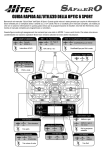
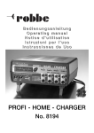
Transmitter description* (Mode 1) - The mode select switch** is located on the back of the transmitter
(*Complete operating instructions for the J6 transmitter can be found in the Download area at www.robbe.com)
Aerial
Neckstrap
lug
Battery display
Operating display
Hover throttle setting
Gyro gain
switch
** After
changing mode
you must switch
the transmitter off
and then on again,
in order to activate
the new mode.
3D switch SW (B)
Throttle off switch SW (A)
Pitch-axis trim
Stick
Pitch-axis / tail rotor
Trainer
Switches
Servo travel reduction
Throttle trim
Stick
Collective pitch / motor speed
and roll
On / Off switch
Tail rotor trim
Roll trim
Mode button
Push-button
Level select
END button
LCD screen
Charge socket
Adjustment
7
Operating Instructions - SOLO PRO 290 RTF 2.4 GHz No. NE2516
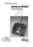
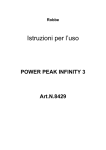
Transmitter description* (Mode 2) - The mode select switch** is located on the back of the transmitter
(*Complete operating instructions for the J6 transmitter can be found in the Download area at www.robbe.com)
Aerial
Battery display
Hover throttle setting
3D switch SW (B)
Throttle off switch SW (A)
Neckstrap
lug
** After
changing mode
you must switch
the transmitter off
and then on again,
in order to activate
the new mode.
Operating display
Gyro gain
switch
Trainer
Switches
Servo travel reduction
Throttle trim
Pitch-axis trim
Stick
Collective pitch / motor speed and
tail rotor
Stick
Pitch-axis / roll
On / Off switch
Tail rotor trim
Roll trim
Mode button
Push-button
Level select
Charge socket
END button
LCD screen
8
Adjustment
Operating Instructions - SOLO PRO 290 RTF 2.4 GHz No. NE2516
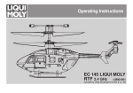
Transmitter LCD display
Collective pitch and throttle adjustment (default settings)
Normal flight
Mode display
Transmitter voltage display
Collective
pitch
Display
Channel reverse channel
display
Throttle
Collective pitch
Throttle
Collective pitch
Stick fully back: Throttle 0%,
collective pitch -6°
Gyro
gain display
Stick centre position:
Throttle 60-65%, collective
pitch -2°
Stick fully forward:
Throttle 100%, collective pitch
+10°
3D flying
Stick fully forward: Throttle
100%, collective pitch +10°
Dual Rate display
Swashplate type
display
Stick centre position:
Throttle 85%, collective pitch
+3.5°
Roll / tail rotor channel display
Throttle / pitch-axis channel display
Stick fully forward:
Throttle 90%, collective pitch
+7.5°
9
Operating Instructions - SOLO PRO 290 RTF 2.4 GHz No. NE2516
Receiver outputs
Charging the flight battery
Pitch-axis
(elevator)
servo
Collective
pitch servo
Roll servo
Front
Tail rotor
servo
Collective
pitch servo
Pitch-axis
(elevator) servo
Receiver
Speed
controller
Motor
Battery
Roll servo
Tail rotor servo
10
Connect the battery charger to the mains PSU, and
plug the PSU into a mains
socket.
The red monitor LED on the
charger lights up, and the
charger emits a brief "beep".
Connect the battery to the
charger.
You will hear a brief "beep"; the green monitor LED flashes during
the charge process.
When the charge process is complete, you will hear a further brief
"beep", and the green monitor LED on the charger glows constantly.
Disconnect the battery from the charger, then disconnect the mains
PSU from the wall socket.
Safety Notes
The battery must not be left unsupervised during the charge process or be placed on an inflammable surface. Protect
from damp. Do not subject it to direct sunshine, and do not
cover the charger.
Do not charge batteries that are hot to the touch. Allow batteries to cool down to ambient temperature. Charge the battery
only using the charger included in the set; do not use any
other charger. The charger should only be used to charge
the battery included in the set. Not suitable for charging the
transmitter battery!
Operating Instructions - SOLO PRO 290 RTF 2.4 GHz No. NE2516
Safety Notes regarding LiPo batteries:
• Do not place the battery in water or any other liquid.
• Never heat or incinerate the pack, or place it in a microwave oven.
• Avoid short-circuits, and never charge the battery with reversed polarity
• Do not subject the battery to pressure or shock loads, and never distort or throw the pack
• Never solder directly to the battery
• Do not modify or open the battery
• Batteries must only be charged with a suitable charger; never connect the battery directly to a mains power supply.
• Never charge or discharge a battery in bright sunlight, or close to a heater or open fire.
• Do not use the battery in areas subject to high levels of static electricity.
• Any of these errors can result in damage to the battery, explosion or fire.
• Keep the battery out of the reach of children
• If electrolyte should escape, do not expose it to fire, as the material is highly inflammable and may ignite.
• Do not allow fluid electrolyte to come into contact with eyes. If this should happen, flush with copious amounts of water and
contact a doctor without delay.
• The fluid electrolyte can also be removed from clothing and other objects by rinsing with copious amounts of water.
LIABILITY EXCLUSION
Since robbe Modellsport is not in a position to monitor the handling of these batteries, we expressly deny all liability and guarantee
claims where the batteries have been incorrectly charged, discharged or handled.
11
Operating Instructions - SOLO PRO 290 RTF 2.4 GHz No. NE2516
Binding the receiver
Pre-flight safety check
This function is required in order to
create the communication link between receiver and transmitter. „Binding“ only needs to be carried out Fig. 1
when the receiver is used with the
transmitter for the first time. It is advisable to place the transmitter 0.5
m or less from the receiver aerial, to
eliminate possible influences from Fig. 2
other transmitters during the binding
process.
Before flying the model check that the receiver battery is fully
charged, and that the transmitter batteries still have adequate
capacity.
Ensure that the throttle stick is at the lowest position (fully back)
before switching the model on, and that all other sticks and switches are in the normal position.
Check that all servos are working perfectly.
Check that each component has been installed correctly.
Check that the whole model is in perfect technical condition.
When it is time to switch the receiver and transmitter on, please
observe the following procedure:
Always switch the transmitter on first, and only then the receiver.
After a flight you should always switch the receiver off first, and
only then the transmitter. If you fail to keep to this sequence, the
model could be uncontrollable.
Check that all linkages are correctly fitted and devoid of lost motion; replace them if necessary. Sloppy linkages result in instability
in flight.
Before flying the model, check that the connection between flight
battery and model is secure. Vibration can cause loose connectors to come adrift in flight, rendering the model uncontrollable.
Fig. 3
Procedure:
1.)
Disconnect the electric motor
from the speed controller (Fig. 1). Fig. 4
2.)Hold the Trainer button pressed in
while you switch the transmitter on. You will now see „S-H“ flashing on the LCD screen, and the buzzer sounds a warning (Figs.
2 and 3).
3.)Place the flight battery close by (Fig. 4) and connect the receiver:
the monitor LED flashes.
4.)Press the Binding button on the receiver: the monitor LED flashes
at a higher rate, indicating that the receiver is entering Binding
mode.
5.)The receiver is ready for use as soon as the LED glows constantly. If the binding procedure was successful, the LCD screen on
the transmitter reverts to the normal information display.
12
Operating Instructions - SOLO PRO 290 RTF 2.4 GHz No. NE2516
Flight preparation
Open the battery compartment and insert the dry or rechargeable cells. Close
the battery compartment. Move all the switches to the forward position, then
switch the transmitter on (Fig. 1). If switch "A" or "B" is in the "ON" position, the
screen will flash, and you will hear a warning "beep". The transmitter cannot be
turned off with the switches in these positions.
Move the collective pitch / throttle stick and trim to their lowest position. Otherwise the motors will not start.
Open the cover of the battery support frame. Slide the fully charged LiPo flight
battery into the support frame on the helicopter as far as it will go (Figs. 2 and 3).
Do not touch the throttle control. Leave the model motionless for at least three
seconds, otherwise the initialisation process will not take place.
Repeat this procedure every time you wish to fly the model.
W
A
Fig. 1
The "3D" aerobatic switch SW(B) should only be operated by experienced pilots.
Moving the switch to the "ON" position sets a system rotational speed suitable
for aerobatics.
The hover rotor speed can be adjusted using the "Hover throttle setting" rotary
knob.
Note: the 2.4 GHz transmitter and receiver are supplied already bound at the
factory. It will only be necessary to bind the system again after a repair, or if you
replace a component.
Fig. 2
Fig. 3
13
Operating Instructions - SOLO PRO 290 RTF 2.4 GHz No. NE2516
Flight preparation
Check the correct position of the swashplate before the first flight. The swashplate must be exactly horizontal when viewed from the side
and front of the model. Position the helicopter on a totally flat surface. Now move the throttle stick to the lowest throttle position, and switch
the transmitter on. Check that the pitch-axis, roll and tail rotor trim are all in the neutral positions. Now connect the flight battery.
Remove the canopy and check the swashplate alignment. If it is not horizontal, you must correct it manually. Remove the battery and
turn the transmitter off. Disconnect the appropriate ball-link. You can adjust the pushrod length by turning the ball-link clockwise or anticlockwise. Re-connect the ball-link. Repeat this step until the swashplate is correctly positioned on the model.
Fine trimming is carried out at the transmitter during test-flying.
Check the main rotor blade attachment. The blades must be able to swivel smoothly, without jamming. They should not be too loose,
otherwise vibration may occur.
Blade tracking adjustment:
When the model is first flown, the blade tracking must be adjusted: slowly open the throttle and check the blade tracking with the system
running. If you detect a difference in blade height (tracking) at hover speed, then you need either to increase the pitch angle of the lower
blade, or reduce the pitch angle of the higher blade.
incorrect rotor blade position
correct rotor blade position
14
Operating Instructions - SOLO PRO 290 RTF 2.4 GHz No. NE2516
Important Notes
The first few flights
Take-off: use the 3D switch for aerobatics only. To take off, slowly and steadily increase rotor speed until the model is hovering
approximately at eye-level. At the same time adjust the trims until
the helicopter is flying stably and hovering over one point. At low
height (approx. 10 - 15 cm above the ground) the model cannot be
trimmed accurately due to the turbulence generated by the rotor.
Ideally the first flight should take place in a large indoor space devoid
of obstructions. If you have to fly the model in the open air, wait for a
day with totally flat calm conditions. We recommend that you ask
an experienced helicopter pilot to help you during the first few flights.
Landing: slowly and steadily reduce the throttle setting until the
model descends and touches down. Never reduce the throttle
setting abruptly.
After the landing disconnect the flight battery from the receiver,
and only then switch the transmitter off.
Caution: Stopping (obstructing) the rotor blades when they are
turning can cause serious damage to the mechanical system,
and may even result in a fire. If the propeller is forcibly stopped,
immediately move the throttle stick back to Idle!
Note regarding the flight battery: as soon as you notice a reduction in motor power, land immediately and disconnect the battery. Never continue flying until the battery is flat, as this causes
a deep-discharge condition which results in permanent damage.
Allow the battery to cool down before recharging it.
Replacing the rotor blades: If a rotor blade is damaged, replace
it immediately. When fitting the new rotor blade, tighten the retaining screw just to the point where the blade still swivels smoothly.
Pilot
Pilot
Pilot
Once the model is properly trimmed, you can practise hovering,
and carry out manoeuvres such as circles, squares, rectangles
and figures-of-eight. Initially it is always best to stand about two
metres away from the model, behind or at right-angles to it; this
avoids giving incorrect control commands. You can fly a square
pattern by alternating the direction of flight: away from the pilot, to
the pilot's right, and then towards the pilot again.
Important: Check the state of charge of the transmitter batteries
before each flight, and recharge them when necessary. It is essential to charge the flight battery before flying the model.
Tip: when the helicopter is flying with the nose pointing towards you, the controls are reversed (apart from the throttle
control).
15
Operating Instructions - SOLO PRO 290 RTF 2.4 GHz No. NE2516
Neutral settings for tail rotor and gyro
Possible problems and their remedies
If you wish to adjust Heading Lock mode on the transmitter, move
the RVMX switch (3-D switch) to the forward position (switched
off), and the G.S. switch (gyro gain switch) to the back position.
Gyro gain should be set to about 70%. Check the neutral position
of the tail rotor linkage after making adjustments at the transmitter. Connect the battery to the helicopter without moving the
transmitter's tail rotor stick or the helicopter. Wait three seconds.
The output arm of the tail rotor servo should now be at an angle
of 90° to the servo (Fig.1). At the neutral position the tail rotor
linkage should be at the centre of the tail rotor shaft (Fig. 2).
Adjust the tail rotor pushrod if necessary (see the illustration of
the tail rotor neutral position).
When you move the tail rotor anti-clockwise, the tail rotor servo must compensate in the clockwise direction. If this is not the
case, switch the gyro to "Reverse" (Fig. 3).
Check that the battery in the helicopter is the correct type, and
that it is fully charged.
Check the collective pitch setting.
Check that the main rotor blades are free to swivel.
Check the main and tail rotors for possible vibration.
Check that the gears mesh together correctly.
Check the tail rotor drive shaft.
Transmitter settings
Channel Adjustment
Curve data
low
Gain (20-25)
Fig. 1
16
Fig. 2
Fig. 3
Dual Rate
high
Operating Instructions - SOLO PRO 290 RTF 2.4 GHz No. NE2516
Causes of problems in flight, and how to eliminate them*
Cause of problem
Blade tracking
Rotor blades running at different heights –
Model constantly vibrates
Main rotor speed too low
Hover setting
Main rotor speed too high
gyro gain Tail turns to one side, Tail not stable at stick
centre position
The tail oscillates during the hover hover or in forward flight
Remedy
Correct tracking by adjusting main rotor pushrods
adjust
Reduce hover collective pitch to about 5°,
(main rotor speed should be around 2,200 rpm).
Raise throttle curve
Adjust main rotor pushrods.
(main rotor speed should be around 2,200 rpm)
Lower hover throttle curve.
Check tail rotor linkage neutral position,
Increase gyro gain.
Reduce gyro gain.
* If you are unable to eliminate the problems, cease flying and ask your dealer for assistance
or use our Technical Hotline: +49 (0)66 44 / 87-777 [email protected]
17
Operating Instructions - SOLO PRO 290 RTF 2.4 GHz No. NE2516
Trim settings Mode 1
Trim settings Mode 2
Throttle trim:
If the rotor starts to move without the
throttle stick being touched, or does not
respond to stick movements, you must
adjust the throttle trim until the rotor is
stationary.
Throttle trim:
If the rotor starts to move without the
throttle stick being touched, or does not
respond to stick movements, you must
adjust the throttle trim until the rotor is
stationary.
Tail rotor trim:
If the model's nose turns to right or left
when it lifts off, adjust the tail rotor trim
buttons to correct the rotation until the
model maintains a stable heading.
Tail rotor trim:
If the model's nose turns to right or left
when it lifts off, adjust the tail rotor trim
buttons to correct the rotation until the
model maintains a stable heading.
Pitch-axis trim:
If the model flies forward or back when
it lifts off, adjust the pitch-axis trim until
it hovers over one point.
Pitch-axis trim:
If the model flies forward or back when
it lifts off, adjust the pitch-axis trim until
it hovers over one point.
Roll trim:
If the model moves bodily to left or right
when it lifts off, adjust the roll trim until it
remains in a stable hover.
Roll trim:
If the model moves bodily to left or right
when it lifts off, adjust the roll trim until
the model remains in a stable hover.
18
Operating Instructions - SOLO PRO 290 RTF 2.4 GHz No. NE2516
Controlling the model in Mode 1
Controlling the model in Mode 2
Lift off:
Landing:
Lift off:
Landing:
Yaw left:
Yaw right:
Yaw left:
Yaw right:
Pitch forward:
Pitch back:
Pitch forward:
Pitch back:
Roll right:
Roll left:
Roll right:
Roll left:
19
Operating Instructions - SOLO PRO 290 RTF 2.4 GHz No. NE2516
robbe Modellsport GmbH & Co. KG hereby declares that this device conforms to the fundamental requirements and other relevant regulations
of the corresponding EC Directive. Under www.robbe.com, you will find the original Conformity Declaration by clicking on the Logo button
"Conform" shown together with the appropriate device description.
This symbol means that you should dispose of electrical and electronic equipment separately from the household waste when it reaches the
end of its useful life. Take your unwanted equipment to your local council collection point or recycling centre. This requirement applies to member countries of the European Union as well as other non-European countries with a separate waste collection system.
Disposal of batteries
Batteries must not be discarded as domestic refuse. To protect the environment, always return exhausted or defective cells to your local recycling centre. These include retail sales outlets for batteries, and communal toxic waste disposal centres. Cover any bare wires with insulating
tape in order to avoid short-circuits.
robbe Modellsport GmbH & Co.KG
Metzloserstraße 38 · D-36355 Grebenhain
Technical hotline: +49 (0)66 44 / 87-777 · [email protected]
Commercial register: Gießen Regional Court HRA 2722
Partner with personal liability:
robbe Modellsport Beteiligungs GmbH Gießen / HRB 5793 Managing Director: E. Dörr
Errors and technical modifications reserved Copyright robbe-Modellsport 2012
Duplication and copying of the text, in whole or in part, is only permitted with the prior written approval of robbe-Modellsport GmbH & Co. KG
20