1
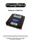
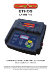
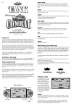
Brushless Speed Controllers FS-HWK008 FS-HWK018 FS-HWK030 FS-HWK040 FS-HWK050 FS-HWK060 FS-HWK075 FS-HWK100 FS-HWK120 FS-HWKPROG Hawk Hawk Hawk Hawk Hawk Hawk Hawk Hawk Hawk Hawk BL BL BL BL BL BL BL BL BL BL 8A Nixx 6~12 / Li-Po 2~4 Cells 18A Nixx 6~12 / Li-Po 2~4 Cells 30A Nixx 6~18 / Li-Po 2~6 Cells 40A Nixx 6~18 / Li-Po 2~6 Cells 50A Nixx 6~18 / Li-Po 2~6 Cells 60A Nixx 6~18 / Li-Po 2~6 Cells 75A Nixx 14~36 / Li-Po 4~12 Cells 100A Nixx 14~36 / Li-Po 4~12 Cells 120A Nixx 14~36 / Li-Po 4~12 Cells ESC Programmer Thank you for purchasing this Fusion Hawk Speed Controller or programmer. We are sure you will be pleased with its performance and features. In order to ensure that you obtain the maximum benefit from its operation, please read the instructions carefully. OpErAting instructions Please keep for Future Reference SPECIFICATIONS Hawk 008 Hawk 018 Hawk 030 Hawk 040 Hawk 050 Hawk 060 Hawk 075 Hawk 100 Hawk 120 Load Current 8A 18A 30A 40A 50A 60A 75A 100A 120A Peak Load Weight (g) 12A 35 x 22 x7 15g 22A 38 x 22 x7 25g 35A 49 x 25 x 10 29g 50A 66 x 25 x 10 47g 60A 66 x 25 x 10 49g 70A 66 x 25 x 10 49g 85A 78 x 29 x 14 79g 120A 73 x 56 x 31 162g 150A 73 x 56 x 31 166g NiCD/NiMH Cells 6~12 6~12 6~18 6~18 6~18 6~18 14~36 14~36 14~36 Li-Po Cells 2~4 2~4 2~6 2~6 2~6 2~6 4~12 4~12 4~12 5.5V max 3A peak 5A Yes 5.5V max 3A peak 5A Yes None None None Dimensions (mm) BEC 5.5V max 2A 5.5V max 2A 5.5V max 3A Programmable Yes Yes Yes 5.5V max 3A peak 5A Yes Yes Yes Yes Rx Filter Yes Yes Yes Yes Yes Yes Yes Yes Yes Low Voltage Cut Off Yes Yes Yes Yes Yes Yes Yes Yes Yes Power on Reset Yes Yes Yes Yes Yes Yes Yes Yes Yes High Motor Frequency 32 kHz 32 kHz 32 kHz 32 kHz 32 kHz 32 kHz 32 kHz 32 kHz 32 kHz Thermal Protection Yes Yes Yes Yes Yes Yes Yes Cool Power FET - - Yes Yes Yes Yes Yes Yes Yes Yes Yes (with Fan) (with Fan) FEATURES Compact & lightweight. “Cool Power” FET technology. Safe Start, prevents the motor starting accidentally. Low Voltage Cut Off (programmed from the battery selection that you make in the set up procedure - NiCd, NiMH, Li-Po). Ideal for: AIRCRAFT, BOATS, CARS & HELICOPTERS. Designed in conjunction with the Fusion Brushless motors, but can be used with any brushless motor. Advanced programming possible with the optional programmer. CONNECTIONS Attach suitable connectors for connection to the drive battery. Red + Positive Black - Negative Ensure all of the connections are suitably insulated with heat shrink sleeving. 1 SETUP Setting the Full Throttle, Stop & Reverse Stick Positions 1) Connect the speed controller as shown in the photograph but DO NOT connect the drive battery yet. 2) Switch the Transmitter “ON”. 3) Move the throttle stick forward to the “FULL THROTTLE” position. 4) Now connect the drive battery to the speed controller. The motor will emit a short series of beeps to confirm the connection. (If the LED lights up, disconnect the drive battery and reverse the servo reverse switch on the transmitter and start again from number 1) 5) After around 10 seconds, the motor will emit a double series of beeps to confirm that it has detected the full throttle position. 6) Within 2 seconds move the throttle stick to the “STOP” position. Again the motor will emit a short series of beeps to confirm that it has detected the stop position. 7) If using the reverse function, move the throttle stick to the “REVERSE” position. The motor will emit a short series of triple beeps to confirm that it has detected the reverse position. If you don‟t require the reverse function, then just leave the throttle stick in the stop position for approximately ten seconds and the controller will confirm the settings with a series of triple beeps. 8) After the triple beeps, disconnect the drive battery to complete the setup. 2 BASIC PROGRAMMING Basic parameters can be edited by moving the throttle stick on the radio, as detailed below. More advanced programming can be performed using the optional programmer unit. ENTERING THE PROGRAMMING MODE 1) Connect the speed controller as shown in the photograph but DO NOT connect the drive battery yet. 2) Switch the Transmitter “ON”. 3) Move the throttle stick forward to the “FULL THROTTLE” position. 4) Connect the drive battery to the speed controller. The motor will emit a short series of beeps to confirm the connection. 5) After around 10 seconds, the motor will emit a double series of beeps. Wait a further 3 seconds and you will hear a triple series of beeps followed by single beeps together with the LED giving a single flashes confirming that Parameter 1 is now selected SELECTING A PARAMETER After entering programming mode, the motor should be emitting a single beep and the LED will emit a single flash to show that parameter 1 is currently selected. To move to the next parameter move the throttle stick from the “Full Throttle” position to the “Stop” position and then back again to the “Full Throttle” position again. The controller will now emit continuous double beeps and the LED will flash twice to show that Parameter 2 has been selected. Repeat the stick movements again and you will hear continuous triple beeps with the LED flashing 3 times to show that Parameter 3 has been selected and so on for Parameters 4 and 5. PROGRAMMABLE PARAMETERS Parameter 1 Parameter Type Battery type Beep 1 LED Flashes 1 Parameter 2 Motor Rotation Direction 2 2 Parameter 3 Brake ON/OFF (Aircraft) Governor ON/OFF (Helicopter) Reverse ON/OFF (Car, Boat) 3 3 Parameter 4 AIRCRAFT / HELICOPTER 4 4 Parameter 5 BOAT / CAR 5 5 3 EDITTING PARAMETERS When you have selected the Parameter you want to change, move the throttle stick from the “Full Throttle” position to the “Stop” position and leave it there for at least 3 seconds. The motor will emit a multi tone bleep to confirm you are now editing a parameter, then the setting for the selected parameter will be displayed and beeped as per the table below. Parameter Number Parameter type LED ON Beep every 2 seconds Li-Po LED FLASHES Beep every 0.5 seconds NiCd / NiMH Normal Reverse 1 Battery Type 2 Direction of Rotation 3 Brake (Aircraft) Governor (Helicopter) Reverse (Car, Boat) OFF OFF OFF ON ON ON 4 Model Type (Aircraft / Helicopter) Model Type (Boat / Car) AIRCRAFT HELICOPTER BOAT CAR 5 IMPORTANT NOTE: Editing parameters 4 or 5 (Model Types) will cause the model type to be changed and the other parameters may be reset. THESE MUST BE SET FIRST before any other parameters are changed. You can then toggle the setting in the parameter by moving the throttle stick from the “Stop” position to the “Full Throttle” position and back again to the “Stop” position. The setting can been seen by the LED being on or flashing and the frequency of the beeps (see the table above). To store the setting, move the throttle stick forward to the “Full Throttle” position and leave it there for at least 3 seconds. The motor will emit a multi tone bleep to confirm you have stored the parameter, then return to the parameter selection menu. 4 PROGRAMMING SUMMARY When the controller is in programming mode, it will flash and beep as detailed in the programming charts above, allowing you to select and edit the parameters. When the throttle stick is held in the ‘FULL THROTTLE’ position, the parameter number is flashed and beeped as detailed in the parameter chart above. Moving the stick down then back up again allows you to move to the next parameter. When the throttle stick is moved to and held in the ‘STOP’ position, the controller will enter the selected parameter and will flash/beep at a different speed, dependant on the current setting. To change this setting, move the throttle stick up and then back down again. To save and exit the parameter, move the stick back to the ‘FULL THROTTLE’ position. 5 PROGRAMMING USING THE OPTIONAL PROGRAMMER PROGRAMMER Connect the programmer as shown in the photograph. SPEED CONTROLLER MOTOR CONNECTIONS DRIVE BATTERY The Programmer is very easy to use. The outer arrows are used to move between the parameters and the „+‟ and „-‟ buttons are used to change the settings within the programming function. Dependant on the model type, the prorgramming functions are laid out as shown in the table below. To change the model type (shown as an icon on the right of the screen) press both outer buttons at the same time. The programming functions that can be accessed using the programmer are detailed in the chart below. Helicopter Select Battery Cut-Off Voltage Cut-Off Type Motor Direction Advance Timing Acceleration Start Power Response to Governor Governor ON/OFF Motor Pole Number Gear Ratio Max. RPM Average RPM Download Restore Memory Back Up Memory N.B. After changing any settings downloaded to the controller. Boat/Car Select Battery Cut-Off Voltage Cut-Off Type Motor Direction Advance Timing Acceleration Start Power Reverse Function Motor Pole Number Gear Ratio Max. RPM Average RPM Download Restore Memory Back Up Memory Aircraft Select Battery Cut-Off Voltage Cut-Off Type Motor Direction Advance Timing Acceleration Start Power Air Brake Type Air Brake ON/OFF Motor Pole Number Gear Ratio Max. RPM Average RPM Download Restore Memory Back Up Memory using the programmer, the new settings must be 6 Model Type Press both outer buttons on the programmer (up and down) at the same time to change the model type between Aircraft, Helicopter, Car & Boat. Battery Type: Use the „+‟ or „-‟ buttons to select the type of battery being used. N.B. It is very important that the correct battery type is selected, as different battery types require the controller to cut-off at different voltages. If a Lithium battery is allowed to discharge below it‟s minimum voltage, then permanent damage can be caused to the battery. Cut-Off Voltage: The Cut-Off Voltage varies according to the battery type that you have set. In “AUTO” mode the cut-off for Li-Po is 3.0V per cell and for NiCd/NiMH is 5.5V (variable cutoff type). However, you can set the range manually using the „+‟ and „-‟ buttons from 4.5V~33.0V. Cut-Off Type: In Cut-Off Type mode you can select the cut-off method when the battery falls below the selected cut-off voltage. Use the „+‟ and „-‟ buttons to switch between the two options of “SOFT OFF” or “HARD OFF”. Motor Direction: The direction of the motor rotation can be selected between NORMAL and REVERSE. Advance Timing: Advance timing or Motor Timing alters the advance of the rotational field which has a similar effect to “advancing the ignition point”. 8° is suitable for most motors, but if you want to use a special setup for your motor we would recommend the following ranges; 0°~10° for in-runner motors and 15°~25° for out-runner motors. Acceleration: You can set the rate of acceleration to your motor using the „+‟ and „-‟ buttons, choosing between Lowest / Low / Normal / High / Highest. Start Power: High / Highest. Similar to “Acceleration”, Start Power allows you to determine the level of power fed to the motor when it starts up. Choosing between Lowest / Low / Normal / 7 Air Brake ON/OFF (AIR mode only): This menu is used for switching the Air Brake On or Off. Air Brake Type: In AIR mode (model aircraft) it is possible to adjust the effect of the motor brake and select whether the motor stops slowly for a soft braking effect or quickly for a hard braking effect. The „+‟ and „-‟ buttons allow you to select from Slow / Normal / Fast. Reverse Function (BOAT & CAR modes only): This menu is used for switching between “One Way” (forward only) and “Two Way” (forward and reverse). Be careful that changing the direction of the motor doesn‟t cancel any of the other settings ! Governor ON/OFF (HELI mode only): This mode is used for switching the speed governor on and off. The Governor mode stabilises the pre-set rotational speed and keeps it virtually constant. Governor Response (HELI mode only): This is used for setting the characteristics of the speed controller in speed governor mode. The available options of Slowest / Slow / Normal / Fast / Fastest can be chosen by using the „+‟ and „-‟ buttons. CAUTION: The faster the value you select, the higher the current draw from the battery. We recommend that you select a fairly low setting to avoid premature damage to the speed controller and drive battery. Motor Pole Number: This menu allows you to enter the number of poles in your motor (between 2~36 poles). This value is very important for indicating the exact rotational speed. Gear Ratio: This menu allows you to enter the gear ratio you are using in your gearbox (from 1.0:1 to 25.0:1). The value for rotational speed indication is calculated using the number of motor poles and the gearbox reduction ratio. Maximum RPM & Average RPM: This mode shows you the maximum and the average rotational speeds recorded during the last flight, using the Motor Pole Number and Gear Ratio values from above. 8 Download: This mode is used for transferring the new settings to the speed controller. Press the „+‟ button to start the process and the programmer will beep once every second until the procedure is complete. If you wish to interrupt the process, press the „-‟ button. Restore Memory: Restore Memory is used to access values which have been stored in the Programmer‟s own memory. Press the „+‟ button to start the process and the programmer then beeps once every second until the procedure is complete. If you wish to interrupt the process, press the „-‟ button. Backup Memory: This mode allows you to store the selected values in the programmer‟s integral memory permanently. Press the „+‟ button to start the process and the programmer then beeps once every second until the procedure is complete. The values set on the speed controller are not affected by this action. If you wish to interrupt the process, press the „-‟ button. WARNINGS Always ensure the correct polarity in all connecting cables. Always avoid short circuits. Keep the speed controller and the programmer dry and away from water, oil and grease. Ensure adequate air circulation around the speed controller. Always keep clear of the rotor blades, propellers and wheels when the drive battery is connected. Always keep within the values stated in the speed controllers specification. 9 www.logicrc.com Logic RC Limited 14 Hartham Lane Hertford SG14 1QN United Kingdom rev.12-09