1
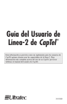
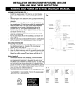
CRYSTAL
PENDANT LAMP
ASSEMBLY INSTRUCTIONS
Model #: 56012-15
56012-20
56012-21
Step 1: TURN OFF ELECTRICITY at main fuse box (or
circuit breaker box) before beginning installation by
switching circuit breaker off or removing fuse. MIN 90º C
SUPPLY CONDUCTORS. CONSULT A QUALIFIED
ELECTRICIAN TO ENSURE CORRECT BRANCH
CIRCUIT CONDUCTOR.
Outlet box (8)
White (neutral) (4)
Wire nut (5)
Mounting screws (19)
Step 2: Fasten universal mounting bracket (7) onto the
outlet box (8) using two outlet box screws (9). Ensure that
all supply circuit wires protrude out of the outlet box (8).
Black (hot) (3)
Ground supply circuit wire (10)
Ground fixture wire (11)
Universal mounting bracket (7)
Outlet box screws (9)
Green screw (12)
Step 3: Strip ¾ in. of insulation from wire ends of fixture
and of supply circuit wires. Attach ground supply circuit
wire (10) and ground fixture wires (11) together with wire
nut (5). Never connect ground wire to black or white
power supply wires. Twist stripped wire ends of fixture
and supply circuit wires together black to black (hot) (3)
and white to white (neutral) (4). Twist on wire nuts (5).
Tape wire nuts and wires together. Carefully tuck
connected wires and wire nuts into outlet box.
(Alternatively, if there is no ground supply circuit wire,
only attach the ground fixture wires (11) to the universal
mounting bracket (7) with the green screw (12)).
Step 4: Place the canopy (13) onto the universal mounting bracket (7); aligning the two canopy holes with the two
mounting screws (19) on universal mounting bracket (7).
Secure into place by screwing two decorative nuts (20).
Step 5: Install light bulbs. Only use bulbs of the specified
type and maximum rated wattage or less. Screw rod (21)
into body fixture (18), followed by upper washers (14),
glass (15), and bottom washers (16), and tighten with
large decorative nut (17).
Use 40 Wattage (Maximum) halogen bulbs. (Bulbs included)
Canopy (13)
Decorative nuts (20)
Bulbs
Body fixture (18)
Rod (21)
Upper washers (14)
Glass (15)
Bottom washers (16)
Large decorative nut (17)
LÁMPARA COLGANTE DE
CRISTAL
INSTRUCCIONES DE ENSAMBLE
Modelo #: 56012-15
56012-20
56012-21
Paso 1: DESCONECTE LA CORRIENTE ELÉCTRICA de la
caja de fusibles principal (o caja cortacircuitos) antes de
comenzar la instalación, para ello, mueva el interruptor del
Blanco (neutro) (4)
circuito a la posición de apagado o quite el
Tuercas para alambre (5)
fusible.CONDUCTORES DE SUMINISTRO DE MÍN. 90º C.
CONSULTE A UN ELECTRICISTA ESPECIALIZADO PARA
Tornillos de montaje (19)
ASEGURARSE DE COLOCAR CORRECTAMENTE EL
CONDUCTOR DEL CIRCUITO DEL RAMAL.
Tornillo verde (12)
Caja de salida (8)
Negro (corriente) (3)
Alambre de tierra del circuito de
suministro (10)
Alambres de tierra de la unidad (11)
Soporte de montaje universal (7)
Tornillos de la caja de salida (9)
Base (13)
Paso 2: Sujete el soporte de montaje universal (7) en la
cajade salida (8) utilizando los dos tornillos (9) de la caja de
salida. Asegúrese de que todos los alambres del circuito de
suministro sobresalgan de la caja de salida (8).
Tuercas decorativas
(20)
Paso 3: Pele un tramo de ¾ de pulgada (2 cm). del
aislamiento en los extremos del alambre de la unidad de
iluminación y de los alambres del circuito de suministro.
Una el alambre de tierra del circuito (10) y el alambre de
tierra de la unidad (11) al junto tuercas para alambre (5).
Nunca conecte el alambre de tierra a los alambres de
alimentación eléctrica negros o blancos. Retuerza los
extremos pelados de los alambres de la unidad junto con
los alambres del circuito de suministro, negro con negro
(corriente) (3) y blanco con blanco (neutro) (4). Atornille las
tuercas para alambre (5). Pegue con la cinta las tuercas y
los alambres. Meta con cuidado los alambres conectados y
las tuercas para alambre a la caja de salida. (Como alternativa, si no hay un alambre de tierra del circuito, sólo una el
alambre de tierra de la unidad (11) a el soporte de montaje
universal (7) con el tornillo verde (12))
Bombillas
Lámpara (18)
Varilla (21)
Arandelas superiores (14)
Paso 4: Coloque la base (13) en el soporte de montaje
universal (7); alineando los dos agujeros de la base con
dos tornillos de montaje (19) en el soporte de montaje
universal (7). Asegure en su lugar atornillando dos tuercas
decorativas (20).
Paso 5: Instale la bombilla. Sólo utilice bombillas del tipo y
voltaje máximo indicado o menor. Atornille la varilla (21) en
la lámpara (18), seguido de las arandelas superiores (14),
la pantalla de cristal (15), y las arandelas inferiores (16), y
apriete con la tuerca grande decorativa (17).
Utilice bombillas halógenas de 40 vatios (máximo). (Bombillas incluidas)
Pantalla de cristal (15)
Arandelas inferiores (16)
Tuerca decorativa grande (17)