Transcript
INSTALLATION INSTRUCTIONS FOR 4130
WARNING! SHUT POWER OFF AT FUSE OR CIRCUIT BREAKER .
AVERTISSEMENT! COUPER LE COURANT AU NIVEAU DES FUSIBLES OU DU DISJONCTEUR.
READ AND SAVE THESE INSTRUCTIONS
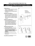
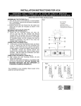
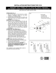
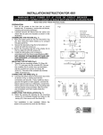
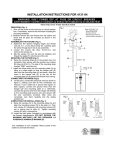
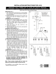
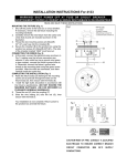
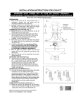
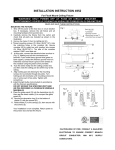
PREPATION (Fig. 1)
1. Shut off the power at the fuse box or circuit breaker
box. If necessary, remove the old fixture including the
mounting hardware.
2. Carefully remove the new fixture from the carton and
check that all parts are included as shown in the
illustration.
MOUNTING THE FIXTURE (Fig.1)
3. Thread the two mounting screws (A) (Size: #832*1.4”L) part way into the crossbar (B). Secure
crossbar (B) to the junction box (not provided) with
junction box screws (C) (Size: #8-32*0.6”L). The length
of mounting screws (A) into crossbar (B) may be
adjusted if necessary. The side of the crossbar
marked “GND” must face out.
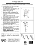
CONNECTING THE WIRES (Fig.2)
4. At this point, connect the electrical wires as shown in
Fig. 2, making sure that all wire connectors are
secured. If your outlet box has a ground wire
(green or bare copper) connect the fixture’s ground
wire to it. Otherwise, connect the fixture’s ground
wire directly to the mounting plate using the green
screw provided. After the wires are connected, tuck
them carefully inside the junction box.
COMPLETING THE INSTALLATION (Fig. 1)
5. Align canopy (D) over mounting screws (A) and
secure with finials (E).
6. Loosen the screws (F), and remove the cup (H).
7. Install the light bulb (not included) in accordance with
the fixture’s specifications. (DO NOT EXCEED THE
MAXIMUM WATTAGE!) (NE PAS DEPASSER LA
PUISSANCE NOMINALE MAXIMALE!)
8. Place the cup (H) onto the glass (J) and secure with
screws (I).
9. Raise the cup (H) over the socket (G) and secure with
screws (F).
Set# A-016
-Crossbar
-Ground screw
-Mounting screw*2
-Junction box screws*2
Fig.1
Fig.2
Your installation is now complete. Return power to the
outlet box and test the fixture.
Note: Loosen the screw (K) and adjust to the
desired height of fixture wire (L), then
re-secure with screw (K).