1
Fan/Light Controls
Lutron Technical Support Center
Rated at 120 V~ 60 Hz
AY2-LFSQ: Fan: 1.5 A, Light: 300 W
TG2-LFSQ: Fan: 1.5 A, Light: 300 W
S2-LF:
Fan: 2.5 A, Light: 300 W
S2-LFSQ:
Fan: 1.5 A, Light: 300 W
S2W-LFSQ: Fan: 1.5 A, Light: 300 W
Important Notes
1.800.523.9466
Installation
2
OFF OFF OFF
ON
ON
ON
Be sure no bare wire is
Small:
exposed.
Strip insulation 3/8 in (10 mm) for 14 AWG (1.5 mm ) wire.
Strip insulation 1/2 in (13 mm) for 16 AWG (1.0 mm ) or
18 AWG (0.75 mm ) wire.
Use to join one 14 AWG (1.5 mm ) supply wire with one
16 AWG (1.0 mm ) or 18 AWG (0.75 mm ) control wire.
Large:
Strip insulation 1/2 in (13 mm) for 10 AWG (6 mm ),
12 AWG (2.5 mm ), or 14 AWG (1.5 mm )wire.
Strip insulation 5/8 in (16 mm) for 16 AWG
(1.0 mm ) or 18 AWG (0.75 mm ) wire.
Use to join one or two 12 AWG (2.5 mm )or
14 AWG (1.5 mm ) supply wires with one
10 AWG (6 mm ), 12 AWG (2.5 mm ), 14 AWG
Large
(1.5 mm ), 16 AWG (1.0 mm ), or 18 AWG
Small
(0.75 mm ) control wire.
2
2
2
2
2
Removing wallplate and switch.
• Remove wall plate and switch mounting screws.
• Carefully remove switch from wall (do not remove wires).
Warning: Before proceeding, verify
that power to the switch is OFF.
Otherwise, death or serious injury
could result.
2
2
2
2
2
2
2
2
2
2
2
2
2
5
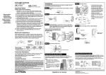
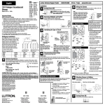
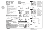
Wire the control.
TAG
3
Multi-Unit Installations
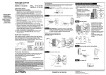
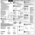
When combining controls in a wallbox, remove all inner side sections before
wiring (see below). Use pliers to bend each side section up and down until it
breaks off. S2-LF controls require reduction of their capacity. Refer to chart
below for maximum capacity. Other fan-speed controls (-LFSQ) do not require
capacity reduction.
Do Not Remove
WARNING: Turn power OFF at circuit breaker or remove fuse.
When making wire connections, follow the recommended strip lengths and
combinations for the supplied wire connectors. Note: Wire connectors
provided are suitable for copper wire only. For aluminum wire, consult
an electrician.
Twist wire connector tight.
Verify application. This dimmer mounts in a single-gang wallbox
and independently controls a ceiling paddle fan and a light with
each slider. Independent wire must be provided for the fan and
light in addition to the feed wire (Live).
Yellow
Tag the wire that is connected to the
feed side of the switch (the side with
the break-off fin).
Red
Black
Outside Sections
Ground
Green
Break-off fin
Live
To Light
Break
Side Sections
Inside Sections Are
Removed From Each
Control
120 V~
60 Hz
Side Sections Are
Removed From Both
Sides Of Middle Control
Model Number
Load
No Sides
Removed
1 Side
Removed
2 Sides
Removed
S2-LF
Fan/Light
2.5 A/300 W
2.1 A/250 W
1.7 A/200 W
Green
• Connect the green ground wire
on the control to the bare copper or green ground wire in the
wallbox.
• Connect the black wire on the
control to the tagged wallbox
wire removed from the switch
(feed wire from the circuit
breaker or fuse box).
• Connect the yellow wire on the
control to the wire leading to the
fan.
• Connect the red wire on the control to the wire leading to the light.
Yellow
Red*
Fan
To Fan
Ground
Light
*Cap off Red wire
if no light is used.
Neutral
Tag
Technical Assistance
If you have questions concerning the installation or operation of this product, call the
Lutron Technical Support Center. Please provide exact model number when calling.
1.800.523.9466 (U.S.A., Canada, and the Caribbean)
Other countries call +1.610.282.3800
Fax +1.610.282.6311
Internet: www.lutron.com
Black
4
Feed (Live)
6
Disconnect switch wires.
Mount and align control. Install wallplate.
Start screws.
Limited Warranty
(Valid only in U.S.A., Canada, Puerto Rico, and the Caribbean.)
Lutron Electronics Co., Inc.
7200 Suter Road
Coopersburg, PA 18036-1299, U.S.A.
Made and printed in China. 10/08 P/N 030-1050 Rev. A
Turn power ON.
Turn screws to loosen.
OFF OFF OFF
7
ON
Align control and
tighten screws.
ON
Lutron will, at its option, repair or replace any unit that is defective in materials or manufacture within one year after
purchase. For warranty service, return unit to place of purchase or mail to Lutron at 7200 Suter Rd., Coopersburg,
PA 18036-1299, postage pre-paid.
THIS WARRANTY IS IN LIEU OF ALL OTHER EXPRESS WARRANTIES, AND THE IMPLIED WARRANTY OF
MERCHANTABILITY IS LIMITED TO ONE YEAR FROM PURCHASE. THIS WARRANTY DOES NOT COVER THE
COST OF INSTALLATION, REMOVAL OR REINSTALLATION, OR DAMAGE RESULTING FROM MISUSE,
ABUSE, OR DAMAGE FROM IMPROPER WIRING OR INSTALLATION. THIS WARRANTY DOES NOT COVER
INCIDENTAL OR CONSEQUENTIAL DAMAGES. LUTRON’S LIABILITY ON ANY CLAIM FOR DAMAGES ARISING OUT OF OR IN CONNECTION WITH THE MANUFACTURE, SALE, INSTALLATION, DELIVERY, OR USE OF
THE UNIT SHALL NEVER EXCEED THE PURCHASE PRICE OF THE UNIT.
This warranty gives you specific legal rights, and you may have other rights which vary from state to state. Some
states do not allow the exclusion or limitation of incidental or consequential damages, or limitation on how long an
implied warranty may last, so the above limitations may not apply to you.
This product may be covered by one or more of the following U.S. patents: 5,191,971; 5,262,678; 5,359,231;
5,637,930; and corresponding foreign patents. Lutron is a registered trademark of Lutron Electronics Co., Inc. NEC
is a registered trademark of the National Fire Protection Association, Quincy, Massachusetts. © 2008 Lutron
Electronics Co., Inc.
ON
P/N 030-1050
1
www.lutron.com
Important Wiring Information
For installations involving more than one control in a wallbox, refer to
Multi-Unit Installations before beginning.
Please read before installing.
1. CAUTION: To avoid overheating and possible damage to other equipment, do not use to control receptacles, fluorescent lighting fixtures, or
transformer-supplied appliances.
2. Controls require separate wires in the wallbox for fan and light.
3. For new installations, wire a test switch before installing the control.
4. Set multispeed fans to their highest setting before installing controls.
5. Use an AY2-LFSQ, S2-LFSQ, S2W-LFSQ or TG2-LFSQ control with a
ceiling paddle fan only. Use only one ceiling paddle fan per control.
6. Use an S2-LF only with fans marked "Suitable for use with solid-state
fan-speed controls."
7. Do not wire an AY2-LFSQ, S2-LFSQ, S2W-LFSQ or TG2-LFSQ in circuit
with a GFCI breaker/receptacle.
8. Controls may feel warm to the touch during normal operation.
9. When no “grounding means” exist within the wallbox then the NEC®
2008, Article 404.9 allows a dimmer without a grounding connection to
be installed as a replacement, as long as a plastic, noncombustible
wallplate is used. For this type of installation, cap or remove the green
ground wire on the dimmer and use an appropriate wallplate such as
Lutron’s Claro® series wallplates.
10. Install in accordance with all national and local electrical codes.
11. Clean control with a soft damp cloth only. Do not use any chemical cleaners.
12. For indoor use only.
13. Controls must be mounted vertically. See stamp on control for
correct positioning.
24 hrs / 7 days
P/N 030-1050
Controles Para Luz y Ventilador
S2-LF:
2,5 A Ventilador, 300 W Luz 120 V~ 60 Hz
S2-LFSQ:
1,5 A Ventilador, 300 W Luz 120 V~ 60 Hz
S2W-LFSQ: 1,5 A Ventilador, 300 W Luz 120 V~ 60 Hz
Notas Importantes
Centro de Soporte Técnico de Lutron
1.800.523.9466
Instalación
Instalaciones de Unidades Multiples
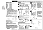
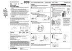
Cuando combine controles en la caja de embutir, elimine todas las secciones laterales internas antes de conectar
los alambres. Vea el diagrama siguiente. Use un alicate para doblarlas cuidadosamente hasta que se despeguen.
Los controles S2-LF requieren reducción en capacidad. Consulte la tabla siguiente para la capacidad máxima del
control. Los otros controles de velocidad (-LFSQ) no requieren reducción de capacidad.
No retire las secciones
exteriores.
1
Cuidado: Apague la corriente en la caja de circuitos o remueva
los fusibles.
Cuando se conecten cables, la longitud expuesta de los extremos y la combinación de conexiones deberán estar de acuerdo con las recomendaciones para
el conector suministrado. Nota: Los conectores suministrados son apropiados
para alambres de cobre únicamente. Consulte a un electricista en caso de
usar conductores de aluminio.
Tuerza el conectador de
Pequeño:
alambre hasta que este
firme.
Alambres de 1,5 mm (14 AWG) quite la aislación en
Asegúrese que no
10 mm (3/8 in) del extremo
queden alambres
Alambres de 10 mm o 0,75 mm (16 o 18 AWG): quite expuestos.
la aislación en 13 mm (1/2 in) del extremo
Úselos para conectar un cable de suministro de 1,5
mm (14 AWG) con un cable de control de 10 mm o
0,75 mm (16 o 18 AWG)
Grande:
Alambres de 6 mm , 2,5 mm o 1,5 mm (10, 12 o
14 AWG): quite la aislación en 13 mm (1/2 in) del
extremo
OFF OFF OFF
2
2
2
2
Remuva la placa de pared y el interruptor.
• Quite los tornillos de montaje del interruptor.
• Cuidadosamente remueva el interruptor de la pared
(no remueva los cables).
Precaución: Comprobar que está
cortada la alimentación a cada
interruptor antes de proceder. El
incumplimiento podría causar
lesiones graves o
mortales.
2
2
2
3
2
Alambres de 10 mm o 0,75 mm (16 o 18 AWG):
quite la aislación en 16 mm (5/8 in) del extremo
Úselos para conectar uno o dos cables de suministro de 2,5 mm o 1,5 mm (12 o 14 AWG) con
un cable de control de 6 mm , 2,5 mm , 1,5 mm ,
1,0 mm o 0,75 mm (10, 12, 14, 16 o 18 AWG)
2
2
2
2
2
2
Verifique la aplicación. Este atenuador se monta en una caja de
embutir sencilla y controla, independientemente, con dos
deslizadores, un ventilador de paletas y una luz. Tiene que existir
un alambre para la luz y otro para el ventilador, además del alambre de alimentación.
2
5
2
Número
de Modelo
S2-LF
A cada control se le
ha quitado la sección
interior.
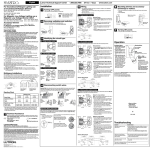
• Conecte el alambre de tierra
verde en el control al alambre
de tierra de cobre sin aislamiento o de verde en la caja de
embutir.
• Conecte el alambre negro en el
control al alambre removido del
interruptor, que está marcado
con una etiqueta.
• Conecte el alambre amarillo del
control al alambre que va al
ventilador.
• Conecte el alambre rojo del
control al alambre que va la a la
luz.
Amarillo
Marque el alambre que está conectado al
costado de alimentación del interruptor (el
costado con la aleta rayada).
Negro
Carga
Secciones
Una Sección
Laterales Intactas Lateral Retirada
Dos Secciones
Laterales Retiradas
Ventilador/Luz
2,5 A/300 W
1,7 A/200 W
2,1 A/250 W
Vivo
120 V~
60 Hz
Al ventilador
Negro
Verde
Amarillo
Rojo*
Ventilador
Tierra
Etiqueta
Asistencia Técnica
Si tiene preguntas referentes a la instalación o operación de este producto, llame a Centro de Soporte Técnico de
Lutron. Por favor suministre el numero exacto del modelo con su llamada.
1.800.523.9466 (E.U.A., Canadá, y el Caribe), para México, llame +1.888.235.2910
de otros países, llame +1.610.282.3800
Fax +1.610.282.6311
Internet: www.lutron.com
Tierra
Verde
A la luz
Al control del medio se la
han quitado las secciones
laterales.
Pequiño Grande
Conecte el control:
Etiqueta
Aleta
rayada
2
2
Rojo
Quibre de las
Secciones
Laterales
www.lutron.com
2
ON
1. Precaución: Para evitar un recalientamiento o el posible daño a otros equipos, no instale para controlar receptáculos, accesorios fluorescentes, equipos motorizados, o equipos subministrados por transformadores.
2. Los controles requieren alambres separados, en la caja de embutir, para el ventilador y la luz.
3. Para instalaciones nuevas, use un interruptor de ensayo antes de probar el control.
4. Fije ventiladores de varias velocidades en la más alta antes de instalar controles.
5. Use un AY2-LFSQ, S2-LFSQ, S2W-LFSQ o un TG2-LFSQ solamente para ventiladores de paletas. Use
solamente un control silencioso por cada ventilador de paletas.
6. Use un S2-LF solamente con ventiladores indicados “Probados para uso con controles de velocidad
de estado sólido”.
7. No conecte un AY2-LFSQ, S2-LFSQ, S2W-LFSQ o un TG2-LFSQ en un circuito con un cortacircuito o
receptáculo de GFCI .
8. Durante la operación normal, el control puede estar tibio al tacto.
9. Si en la caja de embutir no hay acceso a una conexión de tierra, la norma NEC® 2008, Artículo 404.9
permite instalar como reemplazo un atenuador sin conexión a tierra, en tanto se utilice una placa de
pared de plástico no combustible. Para este tipo de instalación, aísle o elimine el conductor verde de
tierra del atenuador y utilice una placa de pared adecuada tal como la ClaroTM de Lutron.
10. Instale de acuerdo a los códigos nacionales y locales gobernando la electricidad.
11. Limpie la unidad con un paño suave y húmedo únicamente. No use agentes químicos de limpieza.
12. Para uso en interiores solamente.
13. Los controles deben ser montados verticalmente. Vea el sello en el control para la posición correcta.
ON
Favor de leer antes de instalar.
24 horas / 7 días
Instrucciones importantes de cableado
Para instalaciones múltiples en una caja de embutir, antes de empezar
consulte las instrucciones para unidades múltiples.
ON
AY2-LFSQ: 1,5 A Ventilador, 300 W Luz 120 V~ 60 Hz
TG2-LFSQ: 1,5 A Ventilador, 300 W Luz 120 V~ 60 Hz
4
Desconecte los alambres del interruptor.
Alimentación
(Vivo)
Luz
*Tape el alambre
Rojo si no se
usará la luz.
Neutro
6
Monte y alinie el control. Instale la placa de pared.
Coloque los
tornillos.
Garantía Limitada
(Válido solamente en los E.U.A., Canadá, Puerto Rico, y el Caribe.)
Lutron Electronics Co., Inc.
7200 Suter Road
Coopersburg, PA 18036-1299, U.S.A.
Hecho e impreso en China. 10/08 P/N 030-1050 Rev. A
English on reverse
OFF OFF OFF
Encienda la corriente.
ON
7
Dele vueltas a los tornillos para soltarlos.
ON
Alinie control y apriete
los tornillos.
ON
Lutron reparará o reemplazará, a su criterio, cualquier unidad cuyos materiales o fabricación resulten defectuosos en el término de un año después de la fecha de
compra. Para obtener servicio de garantía, la unidad debe devolverse al lugar de compra o enviar, con franqueo pago, a Lutron, 7200 Suter Road, Coopersburg,
Pennsylvania 18036-1299.
ESTA GARANTÍA SE OFRECE EN LUGAR DE CUALQUIER OTRA GARANTÍA EXPRESA. LA GARANTÍA IMPLÍCITA DE COMERCIABILIDAD ESTÁ LIMITADA A
UN AÑO, A PARTIR DE LA FECHA DE COMPRA. ESTA GARANTÍA NO CUBRE LOS COSTOS DE INSTALACIÓN, DESMONTAJE NI REINSTALACIÓN. TAMPOCO CUBRE DAÑOS RESULTANTES DE UN USO IMPROPIO O ABUSO, NI DAÑOS DEBIDOS A UNA INSTALACIÓN O CONEXIÓN INCORRECTA. ESTA
GARANTÍA NO CUBRE DAÑOS INCIDENTALES NI RESULTANTES. LA OBLIGACIÓN DE LUTRON CON RESPECTO A CUALQUIER RECLAMACIÓN POR
DAÑOS RELACIONADOS CON LA FABRICACIÓN, VENTA, INSTALACIÓN, ENTREGA, USO, REPARACIÓN O REEMPLAZO DE LA UNIDAD, NO SUPERARÁ, EN
NINGÚN CASO, EL PRECIO DE COMPRA.
Esta garantía otorga derechos legales específicos, pero se podría tener otros derechos, que varían de un estado a otro. Algunos estados no permiten la exclusión o
limitación de daños incidentales ni resultantes, ni limitaciones en la duración de una garantía implícita, por lo cual es posible que las limitaciones mencionadas anteriormente no correspondan en ciertos casos.
Este producto puede estar cubierto por uno o más de los patentes 5,191,971; 5,262,678; 5,359,231; 5,637,930; de los Estados Unidos y por patentes extrangeros
correspondientes. Lutron es una marca registrada de Lutron Electronics Co., Inc.
NEC es una marca registrada de National Fire Protection Association, Quincy, Massachusetts.
© 2008 Lutron Electronics Co., Inc.