Transcript
PART# 4-765, Grev. 9, 03/14
DO NOT USE
FLOAT
CUP
OVERFLOW
PIPE
LOCK RING
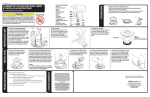
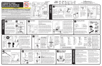
1. THE TOP OF OVERFLOW PIPE (A) must be cut 1” below bottom of
TANK LEVER HOLE (B). Remove tank to bowl
gasket and flush valve lock nut first. Insert
B
flush valve into tank hole. Mark the flush valve
A
1” below bottom of tank lever hole. Remove
WATER
LEVEL
flush valve and cut overflow pipe at specified
mark.
C
2. WATER LEVEL (C) is set below top of
FILL
OVERFLOW
overflow pipe (Fluidmaster recommends 1/2”).
VALVE
PIPE
Code Compliance helps protect your home &
drinking water supply.
Preparing the Fill Valve for Installation (continued)
MEASURE
HEIGHT ONLY:
DO NOT INSTALL
1”
“C.L”
MARK
LOCK
RING
Attach Water Supply Connector
Inspect water supply connector. Replace it if it is
worn or over 5 years old to prevent flooding and property
damage.
A. Attach water supply coupling nut to fill valve. Turn
coupling nut clockwise by hand until tight.
WARNING: Do not over tighten the
nut as it could damage fill valve or
A
coupling nut, resulting in flooding and
property damage. Fluidmaster Click
Seal® connector is recommended: A
perfect seal every time without over
tightening.
B. Turn on water supply and check
for leaks. If you find leaking at bottom
B
of tank, turn nut just enough to stop
leaking. Then flush toilet to check.
9
SHANK
WASHER
RUBBER GASKET
TANK TO BOWL GASKET
Installing Flush Valve
A. Insert flush valve into tank hole.
Position overflow pipe toward back of tank (Do
not cover bolt holes of tank).
B. Holding flush valve in place, thread large
plastic locknut onto threads of flush valve. Hand
tighten locknut and then use large adjustable
pliers to go ½ turn beyond hand tight. Do not
overtighten.
C. Place tank to bowl gasket on bottom of flush
valve locknut. Gasket should cover locknut.
*Note: If you have a Gerber or Kohler two piece
toilet, it is recommended you use a different tank
to bowl gasket.
Gerber: Use an extra thick Gerber gasket.
Kohler: Use a triangular Kohler gasket.
(Both Gerber and Kohler gaskets not included).
6
TANK SHOULD
LOOK LIKE THIS
WHEN SET UP IS
COMPLETE
LOCKNUT
4
A
RUBBER
GASKET
TANK
LOCKNUT
B
RUBBER
GASKET
TANK
LOCKNUT
TANK TO BOWL
GASKET*
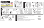
Adjusting Tank Water Level
With water turned on, set float cup to
desired level, by turning water level adjustment
screw. When adjusting float cup, flush tank first.
Then make adjustment while tank is filling.
To adjust tank water, turn adjustment screw
clockwise to raise water level or counter clockwise
to lower water level.
Once adjusted,
flush toilet and
check new level.
Repeat if necessary.
HINT: When you
twist adjustment
screw 8 times float moves 1/2”.
– Please keep a copy of these instructions on the property in which the product was installed.
Sponge
C
B
A
Mini Hack Saw
(Optional)
1
Wire Brush
•
Remove Old Parts
For Three Bolt Toilets
7
REFILL TUBE
NIPPLE
REFILL
CLIP
•
•
•
BOLT HEAD
RUBBER
WASHER
TOILET TANK
A
METAL WASHER
METAL HEX NUT
RUBBER WASHER
METAL WASHER
METAL HEX NUT
•
•
F
Preparing the Fill Valve
for Installation
B
Place Shank
washer onto
threaded
shank of fill
valve. Flat
side up.
D
TANK TO BOWL
GASKET
Installing Lever & Flapper Chain
This indicates the tank is losing water. The fill valve is refilling lost water. Clean flapper and drain seat. If leak continues change flush valve. Install Fluidmaster 507AKR, 540AKR
or 555C kit.
Please ensure all steps were followed in "INSTALLING LEVER & FLAPPER CHAIN" section. Flapper needs to be clipped in to fall evenly on flush valve seat.
Flush valve locknut may not be tight enough. Check locknut and use tools to ensure locknut is tightened 1/2 turn past hand tight.
Make sure the refill tube is supplying water down overflow pipe.
Water level in tank may be too low. Raise water level to 1/2” below top of overflow pipe (See “ADJUSTING TANK WATER LEVEL”). You may have to lengthen the fill valve in
order to increase the water level in tank (See “PREPARING THE FILL VALVE FOR INSTALLATION”).
Flapper may be closing too soon. Give flapper chain approximately 1/2” of slack (See “INSTALLING NEW PERFORMAX™ HIGH PERFORMANCE FLAPPER”).
Bolts are likely not tight enough or a step was missed in “INSTALLING TOILET BOLTS” section. Please ensure all steps were followed in “INSTALLING TOILET BOLTS”
section. Tighten bolts further until tank does not rock and leak stops.
This usually means that tank to bowl gasket is not centered and seated properly. Please ensure all steps were followed in “INSTALLING FLUSH VALVE” section. Tank to
bowl gasket needs to fully cover locknut.
Note: If you have a Gerber or Kohler two piece toilet, it is recommended you use a different tank to bowl gasket. Gerber: Use an extra thick Gerber gasket.
Kohler: Use a triangular Kohler gasket. (Both Gerber and Kohler gaskets not included).
E
Threaded
Shank
If the removed tank lever is bent (see picture) proceed to next step. If the
lever is not bent then proceed to step B.
A
Before installing new tank lever, please remove tank lever lock nut.
A. The new lever will need to be bent like the lever that was just
removed. To bend lever, start bend 2 inches after 90 degree elbow.
Do not bend arm quickly or back and forth repeatedly.
B. Measure length of existing lever arm. If necessary, trim new arm B
at the cut line that best matches the length of the old arm (hacksaw
recommended for best results). Push lever through tank lever hole.
Slide tank lever locknut onto lever arm with flat side of nut facing
tank lever thread.
C. Tighten locknut in the direction shown (clockwise). Do Not Over
Tighten. Lock nut is a reverse thread.
C
Attach the clip of the chain to the tank lever directly above the
flapper. Leave ½ inch of slack in the chain.
Remove top cap and check for debris. If you find debris, or flow is weak: Inspect lower section of fill valve for partial blockage. Partial blockage may be at shut off valve or in
water supply line (See “REMOVING THE VALVE CAP ASSEMBLY & FLUSHING OUT DEBRIS”).
If fill valve has been in use for some time and/or float cup does not drop when flushing tank, replace seal with a genuine Fluidmaster 242 seal (See “IF REPLACING SEAL”).
LEAK OCCURS WHEN TOILET IS FLUSHED
E
Shank
Washer
Adjusting the PerforMAX™ High Performance
Flapper
Turn the rubber portion left or right to select the best flush for your toilet. The
higher the number set in front of the chain connection – the longer the flapper
will stay open. Turn clockwise for greater flush volume. Turn counterclockwise
for lower flush volume.
3.5+ GPF
1.28 & 1.6
GPF
Removing Valve Cap Assembly, Flushing Out Debris, Replacing Seal, & Replacing Valve Cap Assembly
Removing Valve Cap Assembly
If Replacing Seal
Turn off water supply & flush out tank. Push float up with right hand (see picture).
Grip and hold shaft under float with right hand. With left hand, twist cap and lever
counter clockwise 1/8th of a turn to unlock the top cap. Pressing down on top may be
helpful with older valves. Let cap assembly hang on float cup.
Use only a genuine
Fluidmaster 242 seal.
SEAL
LOCATION
Replacing Valve Cap
242
SEAL
LEAKING AT BOLTS AND/OR ON BASE OF TOILET
•
G
Fill Valve Assembly Parts
A) Refill Clip
C
B) Refill Tube
C) Shank Washer
D) Locknut
E) Threaded Shank
IF WATER LEVEL IN BOWL IS TOO LOW
•
•
D
TOILET BOWL
The kit contains two extra rubber washers for toilets that
have three bolts. If you need a third bolt and nut, reuse one
of your existing bolt sets along with the new rubber washers
supplied.
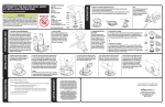
Correct set up of refill
tube and refill clip to
overflow pipe
5
CORRECT ORDER
OF HARDWARE PARTS
IF FILL VALVE TURNS ON AND OFF BY ITSELF, OR IS RUNNING WHEN NO FLUSH HAS TAKEN PLACE
•
(Optional)
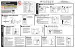
Remove tank lid. Use pencil to mark water level of tank. Then follow
steps A-G.
A. Turn off water supply (Clockwise). Flush toilet and remove excess water from
tank with sponge.
B. Remove water supply coupling nut. Remove locknut from under tank.
C. Remove fill valve from tank.
D. Unhook flapper chain from tank lever.
E. Remove tank lever nut (this is a reverse thread nut). Pull lever from tank.
F. Unbolt tank from toilet bowl. Remove tank and lay on its side on a safe and secure
surface. Remove washers, nuts and bolts. Note: If you have a three bolt tank, save
bolt, washer and nut in best condition for future use. Clean bolt & nut with wire brush
and lubricant spray.
G. Remove tank to bowl gasket from under tank. Loosen and remove flush valve lock
nut and remove flush valve from tank.
IF FILL VALVE DOES NOT TURN ON, WILL NOT TURN OFF, OR WILL NOT REFILL THE TANK AFTER THE FLUSH
•
Lubricant Spray
(Optional)
Installing Toilet Bolts
1. Place one rubber washer on each tank bolt.
2. Place tank bolts through bottom holes of tank.
3. For reinforced connection: Under tank, place metal
washers on thin hex nuts and hand tighten to toilet tank.
Caution: The thin metal hex nut should not touch the toilet
bowl porcelain. If touching, stop and remove nuts and
washers.
4. Set tank onto bowl. Place rubber washers, metal washers
& hex nuts on each bolt under toilet bowl. Using tool, tighten
hex nuts evenly until tank is snug and does not rock.
Installing New Fill Valve
Place fill valve in tank. Make sure lid will sit on top of tank without
touching valve. Align fill valve nipple to face center of tank. Press down on
shank from inside tank while tightening locknut.
Hand-tighten only. DO NOT OVER TIGHTEN. Over
tightening may crack the fill valve or tank causing
flooding. Make sure the float cup does not touch
the tank walls or tank lever and flush valve.
Attach one end of refill tube to refill clip. Place clip
on right side of overflow pipe. Attach other end of
tube to nipple on fill valve with a slight arch (See
drawing to the right). Cut tube as necessary.
WARNING: Do not shove refill tube down overflow
pipe. This may cause significant water waste.
Large Adjustable
Pliers
MIN
8
Position fill valve in tank, but do not fully install yet. Top
of fill valve MUST be set 3” above overflow pipe. This will
automatically place CRITICAL LEVEL MARK / C.L. Mark, 1”
above the top of overflow pipe. Remove fill valve from tank
to adjust height.
Adjust height of fill valve by holding lower shank with
right hand and top of valve with left hand. Twist the lower
shank counter clockwise to increase valve height and
clockwise to decrease valve height. You should hear several
“clicks”. Place valve in tank and check height again. THE
CRITICAL LEVEL MARK, identified by C.L. on valve, MUST
be positioned 1” above top of overflow pipe. This is a
requirement of the Universal Plumbing Code.
Do not move lock ring. It holds the valve body and shank
together under pressure. Do not interchange body with old
shank as leaking can occur.
3
FILL
VALVE
TROUBLESHOOTING
Preparing the Flush Valve for Installation
INSTALLATION
Subject to the “Exclusions” set forth below, Fluidmaster Inc. promises to the consumer to repair, or at the option of Fluidmaster Inc. to replace any
part of this plumbing product which proves to be defective in workmanship or materials under normal use for five years from the date of purchase. All
costs of removal, transportation and reinstallation to obtain warranty service shall be paid by the consumer. During this “Limited Five Year Express
Warranty,” Fluidmaster Inc. will provide, subject to the “Exclusions” section set forth below, all replacement parts free of charge, necessary to correct
such defects. This “Limited Five Year Warranty” is null and void if this plumbing product has not been installed and maintained in accordance with all
written instructions accompanying the product, and if non-Fluidmaster Inc. parts are used in installation.
EXCLUSIONS: FLUIDMASTER INC. SHALL NOT BE LIABLE FOR INCIDENTAL OR CONSEQUENTIAL DAMAGES, INCLUDING COSTS OF INSTALLATION, WATER
DAMAGE, PERSONAL INJURY OR FOR ANY DAMAGES RESULTING FROM ABUSE OR MISUSE OF THE PRODUCT, FROM OVERTIGHTENING OR FROM FAILURE
TO INSTALL OR MAINTAIN THIS PLUMBING PRODUCT IN ACCORDANCE WITH THE WRITTEN INSTRUCTIONS, INCLUDING USE OF NON-FLUIDMASTER
PARTS. DO NOT USE IN-TANK DROP-IN TOILET BOWL CLEANERS CONTAINING BLEACH OR CHLORINE. USE OF SUCH PRODUCTS WILL RESULT IN DAMAGE
TO TANK COMPONENTS AND MAY CAUSE FLOODING AND PROPERTY DAMAGE. USE OF SUCH PRODUCTS WILL VOID THIS WARRANTY.
Before flush valve installation, ensure overflow pipe and water
level of tank are correctly set.
FLUSH
VALVE
PERFORMAX
HIGH PERFORMANCE
FLAPPER
LIMITED FIVE-YEAR EXPRESS WARRANTY
2
(1) Fill Valve
(1) Shank Washer
(1) Locknut
(1) Refill Tube
(1) Refill Clip
(1) Flush Valve
(1) PerforMAX™
High Performance Flapper
(1) Rubber Gasket
(1) Large Plastic Locknut
(1) Tank to Bowl Gasket
(2) Brass Bolts
(4) Stainless Steel Washers
(4) Stainless Steel Hex Nuts
(two thick & two thin)
(6) Rubber Washers
(1) Tank Lever
(1) Tank Lever Locknut
REFILL CLIP
DO NOT USE IN-TANK DROP-IN TOILET BOWL CLEANERS CONTAINING BLEACH OR
CHLORINE. Use of such products will: (1) RESULT IN DAMAGE to tank components and MAY
CAUSE FLOODING and PROPERTY DAMAGE and (2) VOID FLUIDMASTER WARRANTY.
Fluidmaster Flush 'n Sparkle Toilet Bowl Cleaning System is recommended for those
choosing to use in-tank bowl cleaners and WILL NOT VOID the FLUIDMASTER WARRANTY
because it will not damage the components. DO NOT overtighten nuts or tank/bowl may crack. Always use quality
Fluidmaster parts when installing or repairing. Fluidmaster will not be responsible or liable for use of non-Fluidmaster parts
during installation or repair.
Scissors
PARTS IN THIS KIT:
REFILL TUBE
WARNING
Bucket
X
TANK LEVER
30800 Rancho Viejo Road, San Juan Capistrano, CA 92675
www.Fluidmaster.com • 800-631-2011
Contact Fluidmaster for troubleshooting help or visit www.fluidmaster.com
M-F 5:30 am - 5:00 pm PST.
MA
TOOLS
NEEDED
PREPARATION
FLUIDMASTER®
COMPLETE TOILET REPAIR KIT
INSTALLATION INSTRUCTIONS
Flushing Out Debris
Hold cup upside down over uncapped valve to prevent splashing.
Turn water supply on and off a few times. Turn water supply off
when putting cap back on valve.
A. Place cap assembly on top of gray
valve body by aligning cap arm and
adjustment rod next to refill tube.
B. Press down on top cap while rotating
top & arm clockwise to locked position.
A
B