1
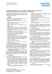
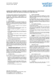
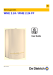
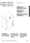
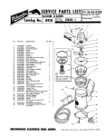
Owner's Manual
Box and Pan Brake
Models: BP-1648H, BP-2248H
WALTER MEIER (Manufacturing) Inc.
427 New Sanford Road
LaVergne, Tennessee 37086
Ph.: 800-274-6848
www.waltermeier.com
Part No. M-752116
Revision A2 03/2011
Copyright © 2011 Walter Meier (Manufacturing) Inc.
Warranty and Service
Walter Meier (Manufacturing) Inc., warrants every product it sells. If one of our tools needs service or repair, one of
our Authorized Service Centers located throughout the United States can give you quick service. In most cases, any
of these Walter Meier Authorized Service Centers can authorize warranty repair, assist you in obtaining parts, or
perform routine maintenance and major repair on your JET® tools. For the name of an Authorized Service Center in
your area call 1-800-274-6848.
MORE INFORMATION
Walter Meier is consistently adding new products to the line. For complete, up-to-date product information, check with
your local Walter Meier distributor, or visit waltermeier.com.
WARRANTY
JET products carry a limited warranty which varies in duration based upon the product (MW = Metalworking, WW =
Woodworking).
WHAT IS COVERED?
This warranty covers any defects in workmanship or materials subject to the exceptions stated below. Cutting tools,
abrasives and other consumables are excluded from warranty coverage.
WHO IS COVERED?
This warranty covers only the initial purchaser of the product.
WHAT IS THE PERIOD OF COVERAGE?
The general JET warranty lasts for the time period specified in the product literature of each product.
WHAT IS NOT COVERED?
Five Year Warranties do not cover woodworking (WW) products used for commercial, industrial or educational
purposes. Woodworking products with Five Year Warranties that are used for commercial, industrial or education
purposes revert to a One Year Warranty. This warranty does not cover defects due directly or indirectly to misuse,
abuse, negligence or accidents, normal wear-and-tear, improper repair or alterations, or lack of maintenance.
HOW TO GET SERVICE
The product or part must be returned for examination, postage prepaid, to a location designated by us. For the name
of the location nearest you, please call 1-800-274-6848.
You must provide proof of initial purchase date and an explanation of the complaint must accompany the
merchandise. If our inspection discloses a defect, we will repair or replace the product, or refund the purchase price,
at our option. We will return the repaired product or replacement at our expense unless it is determined by us that
there is no defect, or that the defect resulted from causes not within the scope of our warranty in which case we will,
at your direction, dispose of or return the product. In the event you choose to have the product returned, you will be
responsible for the shipping and handling costs of the return.
HOW STATE LAW APPLIES
This warranty gives you specific legal rights; you may also have other rights which vary from state to state.
LIMITATIONS ON THIS WARRANTY
WALTER MEIER (MANUFACTURING) INC., LIMITS ALL IMPLIED WARRANTIES TO THE PERIOD OF THE
LIMITED WARRANTY FOR EACH PRODUCT. EXCEPT AS STATED HEREIN, ANY IMPLIED WARRANTIES OR
MERCHANTABILITY AND FITNESS ARE EXCLUDED. SOME STATES DO NOT ALLOW LIMITATIONS ON HOW
LONG THE IMPLIED WARRANTY LASTS, SO THE ABOVE LIMITATION MAY NOT APPLY TO YOU.
WALTER MEIER SHALL IN NO EVENT BE LIABLE FOR DEATH, INJURIES TO PERSONS OR PROPERTY, OR
FOR INCIDENTAL, CONTINGENT, SPECIAL, OR CONSEQUENTIAL DAMAGES ARISING FROM THE USE OF
OUR PRODUCTS. SOME STATES DO NOT ALLOW THE EXCLUSION OR LIMITATION OF INCIDENTAL OR
CONSEQUENTIAL DAMAGES, SO THE ABOVE LIMITATION OR EXCLUSION MAY NOT APPLY TO YOU.
Walter Meier sells through distributors only. The specifications in Walter Meier catalogs are given as general
information and are not binding. Members of Walter Meier reserve the right to effect at any time, without prior notice,
those alterations to parts, fittings, and accessory equipment which they may deem necessary for any reason
whatsoever. JET® branded products are not sold in Canada by Walter Meier.
2
Table of Contents
Warranty and Service .............................................................................................................................. 2
Table of Contents .................................................................................................................................... 3
Warnings ................................................................................................................................................. 4
Specifications....................................................................................................................................... 5
Uncrating and Clean-Up ....................................................................................................................... 5
Brake Setup ......................................................................................................................................... 5
Apron Adjustments............................................................................................................................... 5
Operating the Brake ............................................................................................................................. 5
Adjusting for Metal Thickness ........................................................................................................... 5
Adjusting the Clamping Pressure ...................................................................................................... 5
Flange Capacity................................................................................................................................ 5
Repeat Bends................................................................................................................................... 5
Counter Weight................................................................................................................................. 5
Lubrication........................................................................................................................................ 5
Ordering Replacement Parts.................................................................................................................... 6
Parts List for the BP-1648H & BP-2248H Box & Pan Brake...................................................................... 6
Breakdown for BP-1648H & BP-2248H Box & Pan Brake......................................................................... 7
The specifications in this manual are given as general information and are not binding. Walter Meier
(Manufacturing) Inc., reserves the right to effect, at any time and without prior notice, changes or
alterations to parts, fittings, and accessory equipment deemed necessary for any reason whatsoever.
3
Warnings
1. Keep guards in place and in working order.
2. Keep all body parts away from moving parts. Avoid placing any part of your body near belts, cutters,
gears, etc.
3. Do not exceed rated capacity on this brake.
4. Keep the work area clean. Cluttered areas and workbenches invite accidents.
5. Keep children away. All visitors should be kept a safe distance from the work area.
6. Make your workshop child proof with padlocks, master switches or by removing starter keys.
7. Don't force the machine. It will do the job better and safer at the rate for which it was designed.
8. Use the right machine. Don’t force a machine or attachment to do a job for which it was not designed.
9. Wear proper apparel. Do not wear loose clothing, gloves, neckties, rings, bracelets, or other jewelry,
which may get caught in moving parts. Non-slip footwear is recommended. Wear protective hair
covering to contain long hair.
10. Always use safety glasses. Also use face or dust masks if the cutting operation is dusty. Everyday
eyeglasses only have impact resistant lenses; they are not safety glasses.
11. Don't overreach. Keep proper footing and balance at all times.
12. Maintain tools with care. Keep tools sharp and clean for the best and safest performance. Follow
instructions for lubricating and changing accessories.
13. Never stand on a machine. Serious injury could occur if the machine tipped.
14. Check damaged parts. Before further use of the machine, a guard or other part that is damaged
should be carefully checked to determine that it will operate properly and perform its intended function
- check for alignment of moving parts, binding of moving parts, breakage of parts, mounting, and any
other conditions that may affect its operation. A guard or other part that is damaged should be
properly repaired or replaced.
15. Sheet metal stock has sharp edges. To prevent cuts, use caution when handling.
16. Keep hands and fingers clear of the area in front and rear of the brake.
17. Do not use the machine for any purpose other than for which it was designed
18. Failure to comply with all of these warnings may cause serious injury.
19. Some dust created by power sanding, sawing, grinding, drilling and other construction activities
contains chemicals known to cause cancer, birth defects or other reproductive harm. Some examples
of these chemicals are:
•
•
•
Lead from lead based paint
Crystalline silica from bricks and cement and other masonry products, and
Arsenic and chromium from chemically treated lumber.
Your risk from these exposures varies, depending on how often you do this type of work. To reduce
your exposure to these chemicals: work in a well ventilated area, and work with approved safety
equipment, such as those dust masks that are specifically designed to filter out microscopic particles.
20. Do not operate tool while under the influence of drugs, alcohol or any medication.
4
Specifications
Model Number .............................................................BP-1648H.............................................. BP-2248H
Stock Number.................................................................. 752116.................................................. 752122
Capacity (mild steel) ..................................................... 16 gauge................................................22 gauge
Bending Length Capacity........................................................48”......................................................... 48”
Maximum Box Depth ............................................................... 4”........................................................... 3”
Maximum Lift of Beam ....................................................... 1-1/4”........................................................ 7/8”
Beam Adjustment ..................................................................5/8”........................................................ 1/8”
Number of Fingers and Width ........................ 5@2”, 6@3”, 5@4”.................................5@2”, 6@3”, 5@4”
Finger Nose Angle .................................................................. 45 ......................................................... 45
Finger Nose Radius .............................................................1/32”...................................................... 1/32”
Overall Dimensions (LxWxH) ................................ 61” x 21” x 30”........................................61” x 21” x 28”
Uncrating and Clean-Up
Operating the Brake
1. Remove the crate from around the machine.
Adjusting for Metal Thickness
The holddown assembly must be adjusted to
allow for clearance when making bends
according to the thickness of the material.
Clearance for material within four gauges of the
capacity should be twice the thickness of the
material. For lighter gauges use 1-1/2” times the
thickness. The forward edge of the holddown
fingers should be adjusted parallel to the pivot
edge of the clamp block. Release clamping
pressure on the holddown assembly by pushing
clamp handles (42 & 43) slightly to the rear.
Turn the hex cap screws (64) to adjust for
parallel and proper clearance. The center of the
holddown can be adjusted by tightening the
truss nut on the holddown assembly.
2. Carefully clean all rust protected surfaces
with a mild solvent or kerosene and a soft
rag. Do not use lacquer thinner, paint
thinner, or gasoline. These will damage
painted surfaces.
3. Coat all machined surfaces with a light coat
of oil to inhibit rust.
4. Remove the bolts holding the machine to the
skid.
5. Carefully move the machine to a well-lighted
area on a solid, level workbench, and secure
to the bench with lag screws or bolts.
6. Machine location must allow access to all
sides.
Adjusting the Clamping Pressure
The clamping pressure should be adjusted
according to the thickness of the material. The
clamping pressure should be great enough to
hold the material securely in place but not so
much that it is difficult to lock the clamping
handles. Clamping pressure can be adjusted by
turning the lower nuts (54) on the threaded rod
portion of the yoke assembly (47 & 48).
Brake Setup
The brake will not bend properly if it is not level.
Use a machinist’s level and shims if necessary.
Apron Adjustments
The (#) in the text refers to the breakdown.
Flange Capacity
The apron assembly has been adjusted at the
factory for proper use of capacity material.
During shipment of this unit the machine may
have come out of alignment.
The recommended minimum flange in capacity
material is one inch.
Repeat Bends
The forward edge of the holddown fingers (58,
59 & 60) should be adjusted parallel to the pivot
edge of the clamp block. Release clamping
pressure on the holddown assembly by pushing
clamp handles slightly to the rear. Turn the hex
cap screws (64) to adjust for parallel.
Adjust the stop (81) on the stop rod (69) to limit
the swing of the apron assembly.
The center of the apron can be adjusted by
tightening the truss nut on the apron assembly.
Lubrication
Counter Weight
The counter weight (68) can be moved up or
down to provide more or less leverage.
The machine must be lubricated every day of
service with a few drops of oil. Oil pinholes are
located at both yoke assemblies (47 & 48), and
the apron assembly near the hinge pin (53).
Lightly oil the machined parts when not in use to
prevent rust.
Finger alignment can be achieved by loosening
all socket head cap screws (57) and rotating the
apron (903) to the 90-degree position. This will
align fingers. Tighten screws (57).
5
Ordering Replacement Parts
To order parts or reach our service department, call 1-800-274-6848 Monday through Friday (see our
website for business hours, www.waltermeier.com). Having the Model Number and Serial Number of your
machine available when you call will allow us to serve you quickly and accurately.
Parts List for the BP-1648H & BP-2248H Box & Pan Brake
Index No. Part No.
Description
Size
Qty
900 ........... BP1648N-900 ..........Hold Down Assembly............................................................................. 1
................. BP2248N-900 ..........Hold Down Assembly............................................................................. 1
902 ........... BP1648N-902 ..........Base Assembly...................................................................................... 1
................. BP2248N-902 ..........Base Assembly...................................................................................... 1
903 ........... BP1648N-903 ..........Apron Assembly .................................................................................... 1
................. BP2248N-903 ..........Apron Assembly .................................................................................... 1
40 ............. BP1648N-40 ............Hex Nut ..............................................................M16 ............................ 4
41 ............. TS-155011 ...............Flat Washer ........................................................M20 ............................ 2
42 ............. BP1648N-42 ............Clamp Handle R.H................................................................................. 1
43 ............. BP1648N-43 ............Clamp Handle L.H. ................................................................................ 1
45 ............. BP1648N-45 ............Handgrip ............................................................................................... 2
47 ............. BP1648N-47 ............Yoke Assembly R.H. .............................................................................. 1
48 ............. BP1648N-48 ............Yoke Assembly L.H. .............................................................................. 1
49 ............. BP1648N-49 ............Retainer Ring .....................................................12 ............................... 2
50 ............. BP1648N-50 ............Bushing ................................................................................................. 2
51 ............. BP1648N-51 ............Hex Cap Screw ..................................................M12x30 ...................... 2
52 ............. TS-2276081 .............Set Screw...........................................................M6x8 .......................... 2
53 ............. BP1648N-53 ............Hinge Pin .............................................................................................. 2
54 ............. BP1648N-54 ............Hex Nut ..............................................................M16 ............................ 4
55 ............. BP1648N-55 ............Swivel Pin.............................................................................................. 2
56 ............. BP1648N-56 ............Washer...............................................................M12 ............................ 2
57 ............. BP1648N-57 ............Hex Socket Cap Screw .......................................M8x30 ...................... 16
58 ............. BP1648N-58 ............Finger.................................................................4” ............................... 5
................. BP2248N-58 ............Finger.................................................................4” ............................... 5
59 ............. BP1648N-59 ............Finger.................................................................3” ............................... 6
................. BP2248N-59 ............Finger.................................................................3” ............................... 6
60 ............. BP1648N-60 ............Finger.................................................................2” ............................... 5
................. BP2248N-60 ............Finger.................................................................2” ............................... 5
62 ............. BP1648N-62 ............Clamp.................................................................3” ............................. 11
63 ............. BP1648N-63 ............Clamp.................................................................2” ............................... 5
64 ............. BP1648N-64 ............Hex Cap Screw ..................................................M8x50 ........................ 4
67 ............. BP1648N-67 ............C-Clip .................................................................22 ............................... 2
68 ............. BP1648N-68 ............Counter Weight ..................................................................................... 1
69 ............. BP1648N-69 ............Stop Rod ............................................................................................... 1
70 ............. BP1648N-70 ............Pipe....................................................................................................... 2
71 ............. BP1648N-71 ............Flat Head Screw .................................................M8x16 ........................ 8
72 ............. BP1648N-72 ............Blade..................................................................................................... 1
73 ............. BP1648N-73 ............Angle Support........................................................................................ 1
74 ............. TS-1504041 .............Socket Head Cap Screw.....................................M8x20 ........................ 5
75 ............. BP1648N-75 ............Step Bracket L & R ................................................................................ 2
76 ............. BP1648N-76 ............Socket Head Cap Screw.....................................M8x30 ........................ 1
77 ............. TS-1490011 .............Hex Head Cap Screw .........................................M8x10 ........................ 2
78 ............. TS-1490011 .............Socket Set Screw ...............................................M6x12 ........................ 1
79 ............. 5519949...................Cotter Pin ............................................................125 x .75 ................... 1
80 ............. BP1648N-80 ............Rod ....................................................................................................... 1
81 ............. BP1648N-81 ............Stop ...................................................................................................... 1
82 ............. TS-155010 ...............Flat Washer ........................................................M16 ............................ 2
................. BP1648N-ID.............ID Label (not shown).............................................................................. 1
................. BP2248N-ID.............ID Label (not shown).............................................................................. 1
................. BP1648N-W .............Warning Label (not shown) .................................................................... 1
................. BP1648N-J ..............JET Label (not shown) ........................................................................... 1
83 ............. TS-0571082 .............Hex Nut Jam ......................................................M8 .............................. 2
Breakdown for BP-1648H & BP-2248H Box & Pan Brake
7
WALTER MEIER (Manufacturing) Inc.
427 New Sanford Road
LaVergne, Tennessee 37086
Phone: 800-274-6848
www.waltermeier.com
8