1
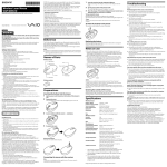
PM 2-L
Bedienungsanleitungde
Operating instructions
en
Istruzioni d’uso
it
Mode d’emploi
Manual de instrucciones
Manual de instruções
fr
es
pt
Gebruiksaanwijzingnl
Brugsanvisningda
Bruksanvisningsv
Bruksanvisningno
Käyttöohje
fi
Használati utasítás
hu
Οδηγιες χρησεως
Instrukcja obsługi
Инструкция по зксплуатации
el
pl
ru
Návod k obsluze
cs
Upute za uporabu hr
Návod na obsluhu Navodila za uporabo Ръководство за обслужване
Instrucţiuni de utilizare
Kulllanma Talimatı
sk
sl
bg
ro
tr
ar
Lietošanas pamācība
lv
Instrukcijalt
Kasutusjuhendet
IНСТРУКЦIЯ З ЕКСПЛУАТАЦIЇ
uk
Пайдалану бойынша басшылықkk
1
1
4
3
2
2
3
4
5
6
7
8
N
"
#
p
"
#
p
"
E
#
E
%
10
9
d1
d0
d2
d0
3
10m
2
1
7
6
5
11
T1
2.5m
2m
Pos. 1
90p
T2
2.5m
Pos. 2
ORIGINAL OPERATING INSTRUCTIONS
PM 2-L line laser
It is essential that the operating instructions are read before the tool is operated
for the first time.
Always keep these operating instructions
together with the tool.
Ensure that the operating instructions are
with the tool when it is given to other persons.
1 These numbers refer to the corresponding illustrations. The illustrations can be found on the fold-out
cover pages. Keep these pages open while studying
the operating instructions.
In these operating instructions, the designation “the
tool” always refers to the PM 2-L line laser.
Parts, operating controls and indicators 1
@ On/off button with LED
; Slide switch for pendulum locking mechanism
= Laser exit window
% Battery compartment
Contents
Page
1. General information
13
2. Description
14
3. Accessories
15
4. Technical data
16
5. Safety instructions
17
6. Before use
18
7. Operation
19
8. Care and maintenance
20
9. Troubleshooting
21
10. Disposal
22
11. Manufacturer’s warranty
22
12. FCC statement (applicable in USA)
23
13. EC declaration of conformity (original)
23
1. General information
1.1 Safety notices and their meaning
DANGER
Draws attention to imminent danger that will lead to
serious bodily injury or fatality.
WARNING
Draws attention to a potentially dangerous situation
that could lead to serious personal injury or fatality.
CAUTION
Draws attention to a potentially dangerous situation
that could lead to slight personal injury or damage to
the equipment or other property.
NOTE
Draws attention to an instruction or other useful
information.
1.2 Explanation of the pictograms and other
information
Warning signs
General
warning
13
en
Symbols
On the tool
>1/4s
en
Read the
operating
instructions
before use.
Disposal of
power tools or
appliances and
batteries
together with
household
waste is not
permissible.
On the tool
CAUTION
LASER RADIATION - DO NOT
STARE INTO BEAM
620-690nm/0.95mW max.
CLASS II LASER PRODUCT
Do not stare into the beam.
Laser warning plates for the USA in accordance with
CFR 21 § 1040 (FDA).
Laser radiation. Do not look into the beam. Laser
class 2.
Laser warning plate according to IEC60825/EN608251:2007
Location of identification data on the tool
The type designation and serial number can be found
on the type identification plate on the tool. Make a
note of this data in your operating instructions and
always refer to it when making an enquiry to your
Hilti representative or service department.
Type:
Generation: 01
Serial no.:
2. Description
2.1 Use of the product as directed
The PM 2-L is a self-leveling line laser which allows leveling and alignment work to be carried out quickly and
accurately by a single person. The tool projects two laser lines (horizontal and vertical) and a line intersection
point. The lines and line intersection point have a range of approx. 10 m. Range depends on the brightness of
ambient light.
The tool is designed for mainly indoor use and is no substitute for a rotating laser.
When used for outdoor applications, care must be taken to ensure that the general conditions are similar to
those encountered indoors. Possible applications are:
Leveling power outlets, cable trays, radiators and in other items in installation work.
Leveling suspended ceilings.
Leveling and aligning doors and windows.
Transferring heights.
Vertical alignment of pipes.
Observe the information printed in the operating instructions concerning operation, care and maintenance.
Modification of the tool is not permissible.
To avoid the risk of injury, use only genuine Hilti accessories and insert tools.
The tool and its ancillary equipment may present hazards when used incorrectly by untrained personnel or
when used not as directed.
2.2 Features
The PM 2-L levels itself automatically within a range of approx. 4°.
Self-leveling takes only approx. 3 seconds.
When the self-leveling range is exceeded, the laser beams blink to warn the user.
The PM 2-L is characterized by its ease of operation and use, its rugged plastic casing and ease of transport
due to its compact dimensions and light weight.
14
The tool can be used together with the PMA 31 laser receiver.
In the normal operating mode, the tool switches itself off after 1 hour. Sustained operating mode can be
activated by pressing and holding the on/off button for four seconds.
2.3 Items supplied with the cardboard box version
1
1
4
1
1
Line laser
Soft pouch
Batteries
Operating instructions
Manufacturer’s certificate
en
2.4 Information displayed during operation
LED
The LED does not light.
The LED does not light.
The LED does not light.
The LED lights constantly.
The LED blinks twice every
10 seconds (pendulum not
locked) or every 2 seconds
(pendulum locked).
The LED blinks.
Laser beam
The laser beam blinks twice
every 10 seconds (pendulum not locked) or every
2 seconds (pendulum
locked).
The laser beam blinks five
times and then remains
permanently on.
The laser beam blinks rapidly.
The laser beam blinks every
2 seconds.
The tool is switched off.
The batteries are exhausted.
The batteries are inserted incorrectly.
The laser beam is switched on. The
tool is in operation.
The batteries are almost exhausted.
The tool is switched off but the pendulum is not locked.
The batteries are almost exhausted.
Automatic power-off has been deactivated.
The tool is unable to level itself (Outside the self-leveling range).
Inclined line operating mode. The
pendulum is locked, as a result of
which the lines are not leveled.
3. Accessories
Designation
Short designation
Tripod
Target plate
Target plate
Laser receiver
Telescopic brace
PMA 20
PMA 54/55
PRA 50/51
PMA 31
PUA 10
Description
15
Designation
Short designation
Universal adapter
Laser visibility glasses
PMA 78
PUA 60
en
Description
The laser visibility glasses are not
protective glasses and thus do not
protect the eyes from laser beams.
As the laser visibility glasses restrict color vision, they should be
worn only when working with the
PM 2-L laser tool. Do not wear the
laser visibility glasses while driving
a vehicle on a public road.
4. Technical data
Right of technical changes reserved.
Range of the lines and intersection point
Level of accuracy setting at room temperature +24
°C (75 °F) 1
Self-leveling time
Laser class
Line width
Self-leveling range
Automatic power-off
Operating status indicator
Power supply
Battery life
Operating temperature
Storage temperature
Dust and water spray protection (except battery
compartment)
Tripod thread (tool)
Weight
Dimensions
without laser receiver: 10 m (33 ft)
with laser receiver: 30 m (98 ft)
±3.0 mm at 10 m (±¹/₈ in at 33 ft)
3 s (typical)
Class 2, visible, 620 - 690 nm, ±10 nm (EN 608251:2007 / IEC 60825 - 1:2007); class II (CFR 21
§1040 (FDA)
Distance 5 m: < 2.2 mm
±4° (typical)
Activated after: 1 h
LED and laser beams
AA‑size batteries, Alkaline batteries: 4
Alkaline battery 2,500 mAh, Temperature +24°C
(+75 °F): 14 h (typical)
Min. -10°C / Max. +50°C (+14 to 122 °F)
Min. -25°C / Max. +63°C (-13 to 145 °F)
IP 54 as per IEC 529
UNC¹⁄₄"
Without batteries: 0.43 kg (0.95 lbs)
65 x 107 x 95 mm (2 ¹/₂ x 4 ¹/₄ x 3 ³/₄ in)
1 Influences such as, in particular, high temperatures, moisture, shock, fall, etc. may lead to deviations from the level of accuracy which was set.
16
5. Safety instructions
WARNING: Ensure that you read all safety precautions and instructions.Failure to observe the safety
precautions and instructions may result in electric
shock, fire and/or serious injury.Retain all safety
precautions and instructions for future reference.
5.1 General safety measures
a) Check the accuracy of the tool before using it to
take measurements.
b) The tool and its ancillary equipment may
present hazards when used incorrectly by
untrained personnel or when used not as
directed.
c) To avoid the risk of injury, use only genuine
Hilti accessories and additional equipment.
d) Stay alert, watch what you are doing and use
common sense when operating the machine.
Don’t use the machine when you are tired or
under the influence of drugs, alcohol or medication. A moment of inattention while operating
machines may result in serious personal injury.
e) Modification of the tool is not permissible.
f) Observe the information printed in the operating instructions concerning operation, care and
maintenance.
g) Do not render safety devices ineffective and do
not remove information and warning notices.
h) Keep children and other persons away from the
area while the tool or appliance is in use.
i) Take the influences of the surrounding area into
account. Do not expose the tool to rain or snow
and do not use it in damp or wet conditions. Do
not use the tool where there is a risk of fire or
explosion.
j) Maintain the machine carefully. Check for misalignment or binding of moving parts, breakage
of parts and any other condition that may affect
the machine’s operation. If damaged, have the
machine repaired before use. Poor maintenance
is the cause of many accidents.
k) Have your power tool serviced by a qualified
repair person using only identical replacement
parts. This will ensure that the safety of the power
tool is maintained.
l) The user must check the accuracy of the tool
after it has been dropped or subjected to other
mechanical stresses.
m) When the tool is brought into a warm environment from very cold conditions, or vice-versa,
allow it to become acclimatized before use.
n) Make sure that the tool is mounted securely
when adapters or accessories are used.
o) Keep the laser exit aperture clean to avoid
measurement errors.
p) Although the tool is designed for the tough conditions of jobsite use, as with other optical and
electronic instruments (e.g. binoculars, spectacles, cameras) it should be treated with care.
q) Although the tool is protected to prevent entry
of dampness, it should be wiped dry each time
before being put away in its transport container.
r) Check the accuracy of the measurements several times during use of the tool.
5.2 Proper organization of the workplace
a) Secure the area in which you are working and
take care to avoid directing the beam towards
other persons or towards yourself when setting
up the tool.
b) Avoid unfavorable body positions when working
from ladders. Make sure you work from a safe
stance and stay in balance at all times.
c) Measurements taken through panes of glass or
other objects may be inaccurate.
d) Ensure that the tool is set up on a steady, level
surface (not subject to vibration).
e) Use the tool only within its specified limits.
f) If several laser tools are used in the same
working area, care must be taken to avoid
confusing the beams.
g) Magnetic fields may affect the accuracy of the tool.
It must thus be kept away from magnetic objects.
The tool is not affected by the Hilti universal
adapter.
h) When working with the receiver, it must be held
exactly at right angles to the laser beam.
i) Do not use the tool in the proximity of medical
instruments.
5.3 Electromagnetic compatibility
Although the tool complies with the strict requirements of the applicable directives, Hilti cannot entirely rule out the possibility of the tool being subject
17
en
en
to interference caused by powerful electromagnetic
radiation, leading to incorrect operation. Check the
accuracy of the tool by taking measurements by other
means when working under such conditions or if you
are unsure. Likewise, Hilti cannot rule out the possibility of interference with other devices (e.g. aircraft
navigation equipment).
5.4 Laser classification for laser class 2/class II
tools
Depending on the version purchased, the tool complies with Laser Class 2 in accordance with IEC8251:2007 / EN60825-1:2007 and Class II in accordance
with CFR 21 § 1040 (FDA). This tool may be used
without need for further protective measures. The
eyelid closure reflex protects the eyes when a person looks into the beam unintentionally for a brief
moment. This eyelid closure reflex, however, may be
negatively affected by medicines, alcohol or drugs.
Nevertheless, as with the sun, one should not look
directly into sources of bright light. Do not direct the
laser beam toward persons.
5.5 Electrical
b) To avoid pollution of the environment, the tool
must be disposed of in accordance with the currently applicable national regulations. Consult
the manufacturer if you are unsure of how to
proceed.
c) Keep the batteries out of reach of children.
d) Do not allow the batteries to overheat and do not
expose them to fire. The batteries may explode
or release toxic substances.
e) Do not charge the batteries.
f) Do not solder the batteries into the tool.
g) Do not discharge the batteries by short circuiting
as this may cause them to overheat and present
a risk of personal injury (burns).
h) Do not attempt to open the batteries and do not
subject them to excessive mechanical stress.
i) Do not use damaged batteries.
j) Do not mix old and new batteries. Do not mix
batteries of different makes or types.
5.6 Liquids
Under abusive conditions, liquid may leak from the
battery. Avoid contact. If contact accidentally occurs, flush with water. In the event of the liquid
coming into contact with the eyes, rinse the eyes
with plenty of water and consult a doctor. Liquid
ejected from the battery may cause irritation or burns.
a) Insulate or remove the batteries before shipping
the tool.
6. Before use
1.
2.
6.1 Inserting the batteries 2
DANGER
Use only new batteries.
18
3.
4.
Open the battery compartment.
Remove the batteries from the packaging and
insert them in the tool.
NOTE Only batteries recommended by Hilti may
be used to power the tool.
Check that the battery terminals are positioned
correctly as shown on the underside of the unit.
Close the battery compartment. Check that the
catch engages properly.
7. Operation
7.1.5 Using the tool with the PMA 31 laser
receiver
For further information, please refer to the PMA 31
operating instructions.
NOTE
To achieve maximum accuracy, project the line onto
a vertical, flat surface. When doing so, set up the tool
at 90° to the surface.
7.1 Operation
7.1.1 Switching the laser beams on
1. Unlock the pendulum.
2. Press the on/off button once or repeatedly until
the desired operating mode is set:
NOTE The tool switches between the operating
modes according to the sequence shown below and then starts again from the beginning
provided that the on/off button is pressed again
within 5 seconds each time.
Horizontal laser line
Vertical laser line
Vertical and horizontal laser lines
7.1.2 Switching the tool/laser beams off
Press the on/off button until the laser beam is no
longer visible and the LED goes out.
NOTE
- The tool can be switched off if the on/off button has
not previously been pressed for at least 5 seconds.
- The tool switches itself off automatically after approx. 1 hour.
7.1.3 Deactivating the automatic power-off
feature
Press and hold the on/off button for approx. 4 sec.
until the laser beam blinks five times as confirmation.
NOTE
The tool will be switched off when the on/off button
is pressed or when the batteries are exhausted.
en
7.2 Examples of applications
7.2.1 Transferring heights 3
7.2.2 Aligning suspended ceilings 4
7.2.3 Aligning pipes vertically 5
7.2.4 Aligning radiators 6
7.2.5 Aligning door and window frames 7
7.3 Checking
7.3.1 Checking the leveling of the horizontal
laser beam 8
1. Place the tool on an even, level surface approx.
20 cm from the wall (A) with the laser beam
directed toward the wall (A).
2. Mark the point of intersection of the laser lines
on the wall (A) with a cross (1).
3. Turn the tool through 180° and mark the point
of intersection of the laser lines on the opposite
wall (B) with a cross (2).
4. Place the tool on an even, level surface approx.
20 cm from the wall (B) with the laser beam
directed toward the wall (B).
5. Mark the point of intersection of the laser lines
on the wall (B) with a cross (3).
6. Turn the tool through 180° and mark the point
of intersection of the laser lines on the opposite
wall (A) with a cross (4).
7. Measure the distances d1 between (1) and (4)
and d2 between (2) and (3).
7.1.4 Inclined line function
Lock the pendulum.
The tool does not level itself automatically.
The laser beam(s) blink(s) every two seconds.
19
8.
en 9.
Mark the mid points of d1 and d2.
If the reference points 1 and 3 are located on
different sides of the mid point, then subtract d2
from d1.
If the reference points 1 and 3 are located on the
same side of the mid point, then add d1 and d2
together.
Divide the result by twice the length of the room
(room length x 2).
The maximum permissible error is 3 mm.
7.3.2 Checking the accuracy of the horizontal
line 9 10
1. Place the tool at the edge of a room with a length
of at least 10 m.
NOTE The floor surface must be even and level.
2. Switch on all laser beams.
3. Set up a target plate at a distance of at least 10 m
from the tool, so that the point of intersection of
the laser lines lies in the center of the target plate
(d0) and the vertical line on the target plate runs
exactly through the middle of the vertical laser
line.
4. Pivot the tool clockwise through 45° (as seen
from above).
5. Then mark the point (d1) on the target plate
where the horizontal laser line strikes the vertical
line on the target plate.
6. Pivot the tool counterclockwise through 90°. The
reference point must remain on the center of the
reference cross.
7. Then mark the point (d2) on the target plate
where the horizontal laser line strikes the vertical
line on the target plate.
8.
Measure the following vertical distances: d0-d1,
d0-d2 and d1-d2.
NOTE The greatest measured vertical distance
must be no more than 5 mm at a working
distance of 10 m.
7.3.3 Checking the vertical lines 11
1. Position the tool at a height of 2 meters.
2. Switch the tool on.
3. Position the first target plate T1 (vertical) at a
distance of 2.5 meters from the tool at the same
height (2 meters), so that the vertical laser beam
strikes the plate. Mark this position.
4. Then place the second target plate T2 at a position
2 meters below the first target plate, so that the
vertical laser beam strikes the plate. Mark this
position.
5. Mark position 2 at the opposite side of the test
setup (mirror image) on the laser line on the
floor at a distance of 5 meters from the tool.
6. Now place the tool on the floor on the mark for
position 2 which you have just made. Direct the
laser beam toward the target plates T1 and T2
so that it strikes the plates close to their center
lines.
7. Read the distances D1 and D2 from each target
plate (distance of the laser line from the center
of the target plate) and calculate the difference
(D = D1 - D2).
NOTE Take care to ensure that the target plates
are parallel to each other and that they are in the
same vertical plane. (Horizontal alignment may
result in measurement error).
If the difference D is greater than 3 mm, the
tool must be returned to a Hilti repair center for
readjustment.
8. Care and maintenance
8.1 Cleaning and drying
1. Blow dust off the glass.
2. Do not touch the glass with the fingers.
3. Use only a clean, soft cloth for cleaning. If
necessary, moisten the cloth slightly with pure
alcohol or a little water.
NOTE Do not use any other liquids as these may
damage the plastic components.
20
4.
Observe the temperature limits when storing
your equipment. This is particularly important in
winter / summer if the equipment is kept inside
a motor vehicle (-25°C to +60°C).
8.2 Storage
Remove the tool from its case if it has become wet.
The tool, its carrying case and accessories should be
cleaned and dried (at maximum 63°C / 145°F). Repack
the equipment only once it has dried completely and
then store it in a dry place.
Check the accuracy of the equipment before it is used
after a long period of storage or transportation.
Remove the batteries from the tool before storing it
for a long period. Leaking batteries may damage the
tool.
8.3 Transport
Use the Hilti toolbox or packaging of equivalent quality
for transporting or shipping your equipment.
CAUTION
Always remove the batteries before shipping the
tool.
8.4 Hilti calibration service
We recommend that the tool is checked by the Hilti
calibration service at regular intervals in order to
verify its reliability in accordance with standards and
legal requirements.
Use can be made of the Hilti calibration service
at any time, but checking at least once a year is
recommended.
The calibration service provides confirmation that the
tool is in conformance, on the day it is tested, with
the specifications given in the operating instructions.
The tool will be readjusted if deviations from the
manufacturer’s specification are found. After checking and adjustment, a calibration sticker applied to
the tool and a calibration certificate provide written
verification that the tool operates in accordance with
the manufacturer’s specification.
Calibration certificates are always required by companies certified according to ISO 900x.
Your local Hilti Center or representative will be pleased
to provide further information.
9. Troubleshooting
Fault
Possible cause
Remedy
The tool cannot be switched
on.
The battery is exhausted.
The battery is inserted the wrong
way round (incorrect polarity).
The battery compartment is not
closed.
The tool or the on/off button is
faulty.
The laser source or laser control
unit is faulty.
The laser source or laser control
unit is faulty.
The temperature is too high or too
low.
The tool is set up on an excessively
inclined surface.
The tilt sensor is faulty.
Replace the battery.
Insert the battery correctly.
Individual laser beams don’t
function.
The tool can be switched on
but no laser beam is visible.
Automatic leveling doesn’t
function.
Close the battery compartment.
If necessary, the power tool should
be repaired by Hilti Service.
If necessary, have the power tool
repaired by Hilti Service.
If necessary, have the power tool
repaired by Hilti Service.
Allow the tool to cool down or
warm up.
Set up the tool on the level.
If necessary, have the power tool
repaired by Hilti Service.
21
en
10. Disposal
en
WARNING
Improper disposal of the equipment may have serious consequences:
The burning of plastic components generates toxic fumes which may present a health hazard.
Batteries may explode if damaged or exposed to very high temperatures, causing poisoning, burns, acid burns
or environmental pollution.
Careless disposal may permit unauthorized and improper use of the equipment. This may result in serious
personal injury, injury to third parties and pollution of the environment.
Most of the materials from which Hilti tools or appliances are manufactured can be recycled. The materials must
be correctly separated before they can be recycled. In many countries, Hilti has already made arrangements
for taking back old tools and appliances for recycling. Ask Hilti Customer Service or your Hilti representative
for further information.
For EC countries only
Disposal of electric appliances together with household waste is not permissible.
In observance of European Directive 2002/96/EC on waste electrical and electronic equipment
and its implementation in accordance with national law, electric tools that have reached the end
of their life must be collected separately and returned to an environmentally compatible recycling
facility.
Dispose of the batteries in accordance with national regulations.
11. Manufacturer’s warranty
Hilti warrants that the tool supplied is free of defects
in material and workmanship. This warranty is valid
so long as the tool is operated and handled correctly,
cleaned and serviced properly and in accordance with
the Hilti Operating Instructions, and the technical
system is maintained. This means that only original
Hilti consumables, components and spare parts may
be used in the tool.
Additional claims are excluded, unless stringent national rules prohibit such exclusion. In particular,
Hilti is not obligated for direct, indirect, incidental
or consequential damages, losses or expenses in
connection with, or by reason of, the use of, or
inability to use the tool for any purpose. Implied
warranties of merchantability or fitness for a particular purpose are specifically excluded.
This warranty provides the free-of-charge repair or
replacement of defective parts only over the entire
lifespan of the tool. Parts requiring repair or replacement as a result of normal wear and tear are not
covered by this warranty.
For repair or replacement, send the tool or related
parts immediately upon discovery of the defect to
the address of the local Hilti marketing organization
provided.
This constitutes Hilti’s entire obligation with regard
to warranty and supersedes all prior or contemporaneous comments and oral or written agreements
concerning warranties.
22
12. FCC statement (applicable in USA)
CAUTION
This equipment has been tested and found to comply
with the limits for a class B digital device, pursuant
to part 15 of the FCC rules. These limits are designed
to provide reasonable protection against harmful interference in a residential installation. This equipment
generates, uses and may radiate radio frequency
energy. Accordingly, if not installed and used in accordance with the instructions, it may cause harmful
interference to radio communications.
reception, which can be determined by turning the
equipment on and off, the user is encouraged to try
to correct the interference by one or more of the
following measures:
However, there is no guarantee that interference will
not occur in a particular installation. If this equipment
does cause harmful interference to radio or television
NOTE
Changes or modifications not expressly approved by
Hilti may restrict the user’s authorization to operate
the equipment.
en
Re-orient or relocate the receiving antenna.
Increase the distance between the tool and receiver.
Consult your dealer or an experienced TV/radio technician for assistance.
13. EC declaration of conformity (original)
Designation:
Type:
Year of design:
Line laser
PM 2-L
2012
We declare, on our sole responsibility, that this
product complies with the following directives and
standards: 2004/108/EC, 2006/95/EC, 2011/65/EU,
EN 12100.
Technical documentation filed at:
Hilti Entwicklungsgesellschaft mbH
Zulassung Elektrowerkzeuge
Hiltistrasse 6
86916 Kaufering
Deutschland
Hilti Corporation, Feldkircherstrasse 100,
FL‑9494 Schaan
Paolo Luccini
Head of BA Quality and Process
Management
Business Area Electric Tools & Accessories
04/2012
Roman Haenggi
Head of BU Measuring Systems
BU Measuring Systems
04/2012
23
Hilti Corporation
2049117 / A2
2049117
Hilti = registered trademark of Hilti Corp., Schaan
W 4209 | 0612 | 00-Pos. 1 | 1
Printed in China © 2012
Right of technical and programme changes reserved S. E. & O.
*2049117*
LI-9494 Schaan
Tel.: +423 / 234 21 11
Fax: +423 / 234 29 65
www.hilti.com