1
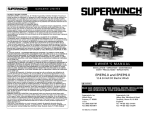
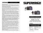
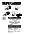
OWNER’S MANUAL
INSTALLATION • OPERATION • MAINTENANCE
SAFETY PRECAUTIONS • REPAIR PARTS
MODEL X1 & X1F
12 & 24 Volt DC Electric Winches
READ AND UNDERSTAND THIS MANUAL
BEFORE INSTALLATION AND OPERATION
OF YOUR SUPERWINCH PRODUCT.
Superwinch, Inc.
Winch Drive
Putnam, CT 06260
U.S.A.
Tel. (860) 928-7787
Fax (860) 928-1143
90-10884 Rev- 05/08/03
Superwinch, Ltd.
Abbey Rise, Whitchurch Road
Tavistock, Devon PL 19 9DR
England
Tel. (1822) 614101
Fax (1822) 615204
GENERAL SAFETY
I N F O R M AT I O N
INTRODUCTION
Thank you very much for purchasing a Superwinch product. We hope and
expect that you will be pleased with the performance and reliability of this
unit. If you are not, for any reason, please contact our Customer Service
Department: (860) 928-7787 USA; (1822) 614101 England.
When requesting information or ordering replacement parts; always give the
following information:
1. Winch Part Number
2. Part Number (found in Replacement Parts List section)
3. Part Description
It is extremely important that you read and understand this Owner’s Manual
prior to installing and using your winch. Pay particular attention to “General
Safety Information” and be sure that anyone else who might use your winch
also studies this section.
Pay particular attention to the caution notes preceded
with this symbol. The notes contain advice for your
protection.
UNPACKING: This carton contains the following items. Please unpack carefully. Read instructions before beginning.
Description
Quantity
Winch assembly with wire rope and hook installed
Switch and harness assembly with two 5' long 8-gauge wires
Handsaver
Circuit breaker assembly with hardware
Poly bag containing: 2 bolts, 2 washers, 2 nuts,
4 flat washers and 5 cable ties
1
1
1
1
1
S P E C I F I C AT I O N S
Motor
Volt Load
Speed
Current
DC
lbs kg Ft/min m/min Amps
Working Load . . . . . 2,000 lbs. (907 kg)
Stall Load . . . . . . . 2,500 lbs. (1,134 kg)
Wire Rope . . . . . . . . . 3/16” x 25 ft.
Voltage . . . . . . . . 12 or 24 Volt DC
Motor . . . . . . . . . . . . . . . . . .1.3 hp
Gear Ratio . . . . . . . . . . . . . . . 123:1
Weight . . . . . . . . . . 18 lbs. (8.2 kg)
0
0
2,000 907
24
0
0
2,000 907
ROLLING LOAD
25
7.6
30
9
2.7
200
25
7.6
20
9
2.7
100
CAPACITY**
Slope*
10% (6º)
20% (11º)
30% (17º)
100% (45º)
Lbs.**
kg**
10,000
4535
6,800
3084
5,200
2359
2,600
1179
Ratings assume a 10% coefficient of friction.
* A 10% slope is a rise of one foot in ten feet. Slope in approximate degrees is also shown above.
** All loads shown are for single-line operation (see Figure 1). Double-line operation with optional
pulley block (P/N 2227) approximately doubles capacity of winch (see Figure 1).
2
1. The X1 winch is rated at 2,000
lbs. (single-line) capacity. DO NOT
OVERLOAD. DO NOT ATTEMPT
PROLONGED PULLS AT HEAVY
LOADS. DO NOT MAINTAIN
POWER TO THE WINCH IF THE
MOTOR STALLS. Overloads can
damage the winch and/or the
wire rope and create unsafe
operating conditions. FOR
HEAVY LOADS, WE RECOMMEND THE USE OF THE
OPTIONAL PULLEY BLOCK AND
HOOK ASSEMBLY (PART NO.
2227) TO DOUBLE-LINE THE
WIRE ROPE (Figure 1). This
reduces the load on the winch
and the strain on the wire rope
by approximately 50%.
Single Line
PERFORMANCE
12
Your new Superwinch is a powerful
machine. Treat it with respect, use it
with caution and always follow
these safety guidelines.
Double Line
Figure 1
2. AFTER READING AND UNDERSTANDING THIS MANUAL,
LEARN TO USE YOUR WINCH.
Practice using it so you will be
familiar with it when the need
arises. Periodically check the
winch installation to assure that
all bolts are tight.
3. DO NOT “move” your vehicle to
assist the winch in pulling a load.
The combination of the winch
and vehicle pulling together
could overload the wire rope and
the winch itself.
4. KEEP WINCHING AREA CLEAR.
Do not allow people to remain in
the area during winching operations. Do not step over a taut
wire rope or allow anyone else to
do so. Do not stand between the
winch and load.
5. INSPECT WIRE ROPE AND
EQUIPMENT FREQUENTLY. A
FRAYED WIRE ROPE WITH BROKEN STRANDS SHOULD BE
REPLACED IMMEDIATELY.
Always replace wire rope
with the manufacturer’s identical replacement part, (see
Replacement Parts List). Never
replace the wire rope with any
kind of rope other than the type
and size specified in the Wire
Rope section of this manual.
6. USE HEAVY LEATHER GLOVES
when handling wire rope. DO
NOT LET WIRE ROPE SLIDE
THROUGH YOUR HANDS. A broken strand could seriously injure
your hands.
7. KEEP CLEAR OF THE WINCH,
WIRE ROPE, AND HOOK WHEN
OPERATING WINCH. NEVER put
your fingers through the hook
when reeling in the last few feet
of line. If your finger should
become trapped in the hook, you
could lose your finger. Use the
HAND SAVER BAR (Figure 2) to
guide the hook within the last
few feet. Never guide a wire rope
on or off the drum with your hand.
Figure 2
3
GENERAL SAFETY
I N F O R M AT I O N
( C O N T. )
8. NEVER HOOK THE WIRE ROPE
BACK ONTO ITSELF. Use a nylon
sling (Superwinch Part No. 1509).
Hooking the wire rope onto itself
can damage the rope (Figure 3).
Wrong
Figure 3
13. AVOID CONTINUOUS PULLS
FROM EXTREME ANGLES as
this will cause the wire rope to
pile up at one end of the drum
(Figure 5). This can jam the wire
rope in the winch, causing damage to the wire rope or winch
itself.
Right
9. It is a good idea to lay a heavy
blanket or jacket over the wire
rope near the hook end when
pulling heavy loads (Figure 4). If
a wire rope failure should occur,
the cloth will act as a damper
and help prevent the rope from
whipping. Raise the hood of the
vehicle for added safety.
Right
Wrong
Figure 5
14. Always operate winch with an
unobstructed view of the winching operation.
15. IT IS RECOMMENDED THAT A
FAIRLEAD BE USED to guide
the wire rope onto the winch.
Two types of fairleads are
offered: the Hawse Fairlead,
Part No. 1507, and the Roller
Fairlead, Part No. 1560.
16. DO NOT OPERATE WINCH
WHEN UNDER THE INFLUENCE
OF DRUGS, ALCOHOL OR
MEDICATION.
Figure 4
10. NEVER USE YOUR WINCH FOR
LIFTING OR MOVING PEOPLE.
The winch is not designed nor
intended for use in lifting or
moving people.
11. Your winch is not designed or
intended for overhead hoisting
operations.
12. DO NOT ATTEMPT PULLS
FROM ANGLES WITHOUT
USING OPTIONAL FAIRLEAD,
P/N 1507 OR 1560, as damage
to winch and wire rope may result.
4
17. ALWAYS REMOVE THE
SWITCH BEFORE WORKING IN
OR AROUND THE WIRE ROPE,
FAIRLEAD, OR WINCH DRUM
(THE DANGER ZONE) so that
the winch cannot be turned on
accidentally.
18. NEVER WORK ON OR
AROUND THE FAIRLEAD OR
WINCH DRUM, WHEN WINCH
IS UNDER LOAD.
19. When using your winch to move
a load, place the vehicle transmission in neutral, set vehicle
parking brake, chock all wheels,
and keep the engine running.
GENERAL SAFETY
I N F O R M AT I O N
( C O N T. )
20. DO NOT USE THE WINCH TO
HOLD LOADS IN PLACE.
Use other means of securing
loads such as tie down straps.
Superwinch offers a wide variety
of tie down straps. Contact your
local Superwinch dealer.
21. USE ONLY FACTORY
APPROVED SWITCHES,
REMOTE CONTROLS, AND
ACCESSORIES. Use of non-factory approved components may
cause injury or property damage
and could void your warranty.
22. DO NOT MACHINE OR WELD
ANY PART OF THE WINCH.
Such alterations may weaken
the structural integrity of the
winch and could void your warranty.
23. Maintain 5 turns of wire rope
around wire rope drum to prevent the wire rope from pulling
off under load.
24. NEVER INSTALL WINCH IN
SUCH A WAY THAT THE
WARNING AND INSTRUCTION
LABELS ARE OBSCURED.
Someone who had not read this
manual may need to see them
to understand the proper operation of the winch. ALWAYS
CHECK FOR CORRECT DIRECTION OF ROTATION BEFORE
USING WINCH. The winch must
be properly wired to ensure correct direction of rotation.
25. When moving a load, slowly
take up the wire rope slack until
it becomes taut. Stop, recheck
all winching connections. Be
sure the hook is properly seated.
If a nylon sling is used, check the
attachment to the load.
26. Always install winch in such a
way that the operator will be
standing with a comfortable
posture, with unobstructed
access to, and a clear view of the
winch, its labels, and its controls.
I N S TA L L AT I O N
TOOLS NEEDED FOR MOUNTING
AND WIRING
Open End Wrenches – 9/16", (2), or
small adjustable wrenches, wire
strippers, or cutters, terminal
crimpers (pliers), torque wrench, Pair
3/8" bolts and nuts, four flat and
two lock washers.
MOUNTING
The mounting location for the
winch must be capable of handling
the loads of the job you intend the
winch to do. Suggested locations
are: a flat front or rear bumper of a
vehicle, on a pickup truck bed or the
winch stand on a trailer.
The winch can be mounted in a horizontal or vertical position (Figure
6). Do not mount the winch where
there would be the possibility of it being submerged in water.
The winch is weather resistant but
not waterproof.
Superwinch mounting (fitting) kits
are available for most popular vehicles. If you can’t obtain a kit locally,
contact Superwinch at the address
listed in this manual for the name of
a Superwinch dealer near you.
Vertical
Horizontal
Figure 6
5
MOUNTING (CONT.)
Drill two 7/16" (12mm) diameter
holes with center lines exactly
3-11/16" (93.66mm) apart (Figure 7)
in the support chosen for the
winch. Attach the winch to the support with two (2) 3/8-16 Hex Head
Bolts. Be sure the hardware is
assembled as shown. Tighten the
hardware to 35 lb. ft. torque.
Bolt
Flat Washer
Flat Washer
Lock Washer
Nut
Figure 7
to the battery negative terminal
(Figure 8). Be sure connections are
clean and tight. Do not connect the
switch or wiring to any other power
source in the vehicle.
Circuit
Protector
Circuit
Chassis Protector
Ground
Red
ELECTRICAL INSTALLATION
This winch operates on standard
automotive 12-or 24-volt Direct
Current.
If it is necessary to drill holes, to
feed the wires, be sure the wires
are protected from damage by
using a grommet (Figure 9). Use
cable ties to secure wires along the
route.
Grommet
Tie Strap
Figure 9
6
Solenoid
Figure 8
Be Prepared
The red wire from the switch is
connected to the circuit protector
terminal using the hardware provided. The other end of the circuit
protector is connected to the battery positive terminal. The black
wire from the switch is connected
Red
Battery
Cable
Figure 10
Do not
connect winch
to 110 Volt house current. Motor
damage or fatal shock may occur.
Automobile
batteries contain gasses which are flammable and
explosive. Wear eye protection during installation and remove all metal
jewelry. Do not lean over the battery while making connections.
Circuit
Protector
Black
Starting at the winch, feed the
wires into the engine compartment.
If possible, use the routing and support for the existing wiring.
Support
From Switch
When you make the ground connection, be sure to scrape off any
dirt from the bolt that would prevent a good connection.
Note: If the winch is mounted at
the rear of the vehicle, a special
wiring kit (P/N 1520) is available
from Superwinch.
If connection to the battery positive
terminal is not possible because of
the terminal design, connect the
circuit protector to the starter
solenoid “hot” side. Determine the
“hot” side by tracing the battery
cable to the solenoid connection.
Connect the red supply wire to the
same terminal to which the battery
cable is connected (Figure 10).
Secure the switch to the motor by
tightening the round thumb screw
on the outside of the switch (Figure
12). The screw threads into the
tapped hole between the brass
motor contact (Figure 11). Do not
use pliers or over-tighten the thumb
screw.
Note: Special adapters are available
from your local Auto Parts Dealers
for making connections to Side Post
Batteries.
The switch and motor end are
designed so the switch will mount
properly only when installed as
shown in Figure 11. Do not attempt
to install the switch in the opposite
direction. If the switch is installed
incorrectly and electrical contact
made, the winch will run in a direction opposite that is indicated on
the product label resulting in possible operator injury.
When extending the lead wires for
rear vehicle mount, always use 8
gauge wire or heavier to extend the
existing wires to the battery.
Figure 12
After the switch is in place, remove
excess slack from the wiring harness
in the vehicle by doubling over
slack areas and tying securely. Do
not leave any dangling or loose
wiring.
Switch
Wires
Figure 11
7
O P E R AT I O N
SWITCH OPERATION
When the switch springs back to the
“OFF” position, an electrical shunt provides dynamic braking action which
prevents the winch from coasting
(Figure 13). THIS BRAKING ACTION IS
NOT A LOAD HOLDING DEVICE.
When the switch is centered in the
“OFF” position, the shunt reduces the
action of a load backdriving the winch.
However, a load can cause the winch
to creep. With the switch removed
from the winch, there is a greater tendency for a load to backdrive the
winch.
Off
Rope In
LUBRICATION
Your new winch has lifetime lubrication. There will be some grease leaking
out of the winch, especially during the
first few operations. This is normal and
it is not necessary to grease or oil any
part of the winch at any time.
WIRE ROPE
A part of your winch that will require
periodic attention and eventual
replacement is the wire rope. Inspect
the wire rope for wear frequently. If
fraying exists, replace the wire rope at
once. Your winch uses 3/16" diameter
galvanized aircraft type 7 x 19 wire
rope that is 25 feet long (4,200 lb.
breaking strength). Always replace the
wire rope with Superwinch replacement wire rope, P/N 1511 (see
Replacement Parts List).
Rope Out
Figure 13
The winch is
not designed
as a load holding device.
The switch should be removed from
the winch when unattended to prevent unauthorized operation. A
Quickconnect (Superwinch P/N 1551) is
also available as an accessory to disarm
the winch. Because the winch will not
hold a load, in trailing or load holding
applications, tie down ropes or straps
must be used to secure loads.
Remote operation of the switch
(Figure 14) can be achieved by tying
one end of a cord through each “ear”
of the switch.
FREE SPOOL OPERATION MODEL X1F
To disengage the clutch for freewheeling the wire rope out, pull
the knob at the wire rope end of
the winch straight out and rotate
the knob 90° (1/4 turn). The wire
rope can be pulled out by hand
(Figure 15). Avoid jerking the wire
rope off the drum when freespooling as this can cause the wire rope
to backlash and snarl on the drum.
Note: The clutch cannot be
released if there is a load on the
wire rope.
To engage the clutch, turn the
clutch knob until the square key
drops into the inner drum shaft
(Figure 16). Activate the control
switch on the winch until the key
drops into the outer drum shaft.
Check that the key is fully engaged
before applying a load to the wire
rope.
Figure 14
Figure 15
MAINTENANCE
Periodically check tightness of the
mounting bolts and electrical connections. Remove any dirt or corrosion that may have accumulated on
the electrical connection.
LUBRICATION
Your new winch has lifetime lubrication. There will be some grease
leaking out of the winch, especially
during the first few operations. This
is normal and it is not necessary to
grease or oil any part of the winch
at any time.
WIRE ROPE
A part of your winch that will
require periodic attention and
eventual replacement is the wire
rope. Inspect the wire rope for wear
frequently. If fraying exists, replace
the wire rope at once. Your winch
uses 3/16" diameter galvanized aircraft type 7 x 9 wire rope (4,200 lb.
breaking strength). Always replace
the wire rope with Superwinch
replacement wire rope, P/N 1511
(See pages 12 and 13).
Figure 16
MAINTENANCE
Periodically check tightness of the
mounting bolts and electrical connections. Remove any dirt or corrosion
that may have accumulated on the
electrical connections.
8
9
TROUBLE SHOOTING
If the winch motor labors and then
stops, the load is too great.
Evidence of this will be a motor
almost too hot to touch. Repeated
occurrence of this condition indicates that the load exerted on your
winch is beyond its capacity and
may burn out the winch motor. Use
of the accessory pulley block, P/N
2227, will increase the winch‘s
capacity.
MOTOR DOES NOT OPERATE
Follow these steps in order. Make
sure your vehicle engine is running
and then try operating your winch
after each step.
1. Remove switch, then replace it on
the motor, making certain that it
is aligned properly over brass
motor connectors and that thumb
screw is snug.
2. If motor does not operate, check
all electrical connections on battery and ground, making sure
that they are clean and tight.
3. Check the wiring harness to
determine if all insulation is
intact. Damaged insulation could
cause a short circuit.
TIPS F0R EXTENDING THE LIFE OF
YOUR WINCH
1. KEEP A TIGHTLY AND EVENLY
WOUND WIRE ROPE DRUM. Do
not allow the wire rope to
become loosely wound. A looselywound drum allows a wire rope
under load to work its way down
into the layers of wire rope on
the drum. When this happens,
the wire rope may become
wedged within the body of the
10
windings, damaging the wire
rope. To prevent this problem,
keep the wire rope tightly and
evenly wound on the drum at all
times. During winching, periodically check to see that the wire
rope is winding on evenly. A
good practice is to rewind the
wire rope under tension after
each use. One way to do this is to
attach the hook to a stationary
object at the top of a small hill or
incline and winch your vehicle up
the incline.
2. DO NOT ALLOW MOTOR TO
OVERHEAT. Remember, the
winch is only for intermittent use.
During long or heavy pulls the
motor will get hot. The internal
parts will be hotter than the case.
To check the motor temperature,
stop winching and carefully touch
the motor. If the motor is uncomfortably warm, allow the motor
to cool before continuing. Keep
the engine running to recharge
the battery during this break.
3. USE A PULLEY BLOCK FOR
HEAVY LOADS. To maximize
winch and wire rope life, use a
pulley block, P/N 2227, to doubleline heavier loads.
5. PREVENT KINKS BEFORE THEY
OCCUR.
a
b
c
Figure 18
a. This is the start of a kink. At this time,
the wire rope should be straightened.
b. The wire rope was pulled and loop has
tightened into a kink. Wire rope is now
permanently damaged and must be
replaced.
c. The result of kinking is that each
strand pulls a different amount causing
strands under greatest tension to break
and reduce load capacity of the wire
rope. The wire rope must be replaced.
6. EQUIPPING THE WINCH WITH A
ROLLER FAIRLEAD, P/N 1560,
Figure 19, will substantially
reduce wear on the wire rope
during angle pulls. The rollers
eliminate heavy rubbing and
abrasion to the wire rope.
Figure 17
4. The pull required to start a load
moving is often much greater
than the pull required to keep it
moving. AVOID FREQUENT
STOPPING AND STARTING
DURING A PULL.
Figure 19
11
REPLACEMENT
PA R T S L I S T
Reference
Number
1
2
3
4
5
6
7
8
9A
9
11
12
13
14
15
16
17
18
19
20
NS
Reference
Number
Description
Handsaver
Rotating Gear Drum
Perimeter Bearing
Carrier Bearing
Planetary Gearing Assembly
Nylon Step Washer
10-Tooth Sun Gear
Flat Thrust Washer
Stationary Ring Gear w/ Needle Bearing
12 Volt Motor w/Ring Gear & Needle Bearing
24 Volt Motor w/Ring Gear & Needle Bearing
Shim Washer
Bushing
5/16" Socket Head Cap Screw
Main Frame Base Plate
Repair Switch Assembly w/ two 3 ft. leads (includes
two butt splices for connecting to old harness)
3/16" x 25' Cable & Hook Assembly
12V Circuit Breaker Assembly
24V Circuit Breaker Assembly
Rope Retainer
Pair of 3/8" Bolts & Nuts, 4 Flat Washers &
2 Locking Washers
Handsaver Label
Pulley Block
AR denotes “As Required”
12
REPLACEMENT
PA R T S L I S T
Part Number
Qty
89-32300
90-32038
90-23137
90-23140
90-23138
90-12418
90-22865
90-23120-08
90-12629
90-32425
90-32429
90-23120-05
90-12174
90-23056-02
90-41019
1519A
1
1
1
2
1
1
1
1
1
1
1
AR
1
2
1
1
1511
90-22873
90-22873-01
90-12419
1
1
1
1
90-22892
90-12417
2227
1
1
1
Description
Part Number
Handsaver
Rotating Drive Shaft Assembly
Drum Assembly
Perimeter Bearing
Carrier Bearing
89-32300
90-32057-01
90-32054
90-23137
90-23140
1
1
1
1
1
6
7
8
9
10
Planetary Gear Assembly
Nylon Step Washer
10 Tooth Sun Gear
Flat Thrust Washer
1.3 HP 12 Volt Motor w/Gearbox & Needle Bearing
1.3 HP 24 Volt Motor w/Gearbox & Needle Bearing
90-23138
90-12418
90-22865
90-23120-08
90-32425
90-32429
1
1
1
1
1
1
10A
11
13
14
15
Stationary Gear w/Needle Bearing
Washer
Freespooling Knobshaft Assembly
5/16" Socket Head Cap Screw
Pair of 3.8" Bolts & Nuts, 4 Flat Washers &
2 Locking Washers
90-12454
90-23120-11
90-12534
90-23056-02
90-22892
1
1
1
1
1
16
17
20
21
22
Base Plate
Outboard Housing
Flange Bushing
Cable Tension Set
3/16" x 25' Wire Rope & Hook Assembly
(Model 1141, 1142)
3/16" x 50' WIre Rope w/out Hook (Model 1177)
Clevis Hook (Model 1177)
3/16" x 50' Wire Rope & Hook Assembly
(Model 1181A)
90-32067
90-32058
90-23167-01
90-12536
1
1
1
1
1511
1511E
90-22812
1511A
1
1
1
1
1
2
3
4
5
AR denotes “As Required”
Qty
13
REPLACEMENT
P A R TPSA R
LT
I SST L(I CS O
T N T. )
Reference
Number
25
26
27
28
29
NS
14
Description
Part Number
Qty
Freewheel Label
Handsaver Label
Repair Switch with 3' Leads
Assembly of two Circuit Breakers on bracket (12V)
Assembly of two Circuit Braekers on bracket (24V)
Cable Retainer
Pulley Block
90-12520
90-12417
1519
90-22873
90-22873-01
90-23164-04
2227
1
1
1
1
1
1
1