1
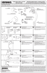
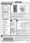
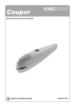
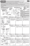
INSTALLATION INSTRUCTIONS FOR TUBULAR
KNOB AND LEVER HANDLE LOCKSETS
INSTRUCCIONES DE INSTALACIÓN PARA CONJUNTOS DE
CERRADURA DE PERILLA TUBULAR Y MANIJA DE PALANCA
FOR BRINKS KEYED ENTRY, INTERIOR LOCKING, AND INTERIOR
NON-LOCKING KNOB AND LEVER HANDLE LOCKSETS
PARA CONJUNTOS DE CERRADURA DE BRINKS DE PERILLA Y PALANCA
DE ENTRADA E INTERIORES CON LLAVE, E INTERIORES SIN LLAVE
For Replacement Installation Instructions,
(S2) MACHINE SCREWS (2)
Instrucciones para instalación de reemplazo:
Remove existing door lock, latch assembly, and strike plate and begin at Step 4.
TORNILLOS (S2) PARA METAL (2)
For New Installation Instructions,
Instrucciones para instalación nueva:
Begin at Step 1
INSIDE LEVER
MANIJA INTERIOR
Quite la cerradura, el cerrojo y la hembra del cerrojo instaladas y empiece en el
Paso 4.
Empiece en el Paso 1.
OUTSIDE LEVER
MANIJA EXTERIOR
LATCH
CERROJO
SQUARE CORNER
FACEPLATE
PLACA FRONTAL
CON ESQUINAS
CUADRADAS
PRIVACY KEY
LLAVE DE PRIVACIDAD
ANTI-PRY SHIELD*
ESCUDO ANTIPALANCA*
BED & BATH INTERIOR LOCKSETS ARE PROVIDED
WITH A PRIVACY KEY FOR LOCKING & UNLOCKING
ALTHOUGH A FLATHEAD SCREWDRIVER WILL ALSO
WORK.
INSIDE KNOB
PERILLA INTERIOR
SE PROVEEN LOS CONJUNTOS DE CERROJOS PARA
PUERTAS INTERIORES DE RECÁMARAS Y BAÑOS
CON UNA LLAVE DE PRIVACIDAD PARA CERRAR Y
ABRIR AUNQUE TAMBIÉN SE PUEDE UTILIZAR UN
DESARMADOR PLANO.
(S1) LATCH SCREWS (2)**
TORNILLOS (S1)
DE CERROJO (2)**
STRIKE PLATE
PLACA DE LA
HEMBRA DEL
CERROJO
(S3) STRIKE PLATE SCREWS (2)**
TORNILLOS (S3) DE PLACA HEMBRA (2)**
KEYS (2)*
LLAVES (2)*
*PARA CERRADURAS DE ENTRADA CON LLAVE
**BED & BATH AND HALL & CLOSET LOCKSETS ARE PROVIDED
WITH FOUR (S1) LATCH SCREWS, WHICH ARE USED FOR BOTH
LATCH AND STRIKE INSTALLATION.
**LOS CONJUNTOS DE CERRADURAS PARA RECÁMARAS Y
BAÑOS, Y PARA PASILLOS Y CLOSETS, SE PROPORCIONAN CON
CUATRO TORNILLOS (S1) DE CERROJO, LOS CUALES SE
UTILIZAN TANTO PARA LA INSTALACIÓN DEL CERROJO COMO
DE LA PLACA HEMBRA
OUTSIDE KNOB
PERILLA EXTERIOR
1
Mark Door with Template
Marque la Puerta con la Plantilla
a. Mark the center line for the lockset about 38” (965 mm)
from the floor.
b. Apply the template to the door with the dotted fold line on the
door edge.
c. Select 2-3/8" (60 mm) or 2-3/4" (70 mm) backset as desired
and mark center of hole on door face. (Most residential doors
have a 2-3/8" backset.)
d. Mark the center for the latch hole on the door edge according
to the thickness of your door.
a. Marque la línea central para el juego de cerradura
aproximadamente a 965 mm (38") del piso.
b. Coloque la plantilla sobre la puerta con la línea punteada de
doblez en el borde de la puerta.
c. Seleccione una distancia o “entrada” (del canto o borde) de
60 mm (2-3/8") o de 70 mm (2-3/4") según corresponda y marque
el centro del agujero en la cara de la puerta. (La mayoría de las
puertas residenciales tienen una distancia del canto o borde de la
puerta de 60 mm (2-3/8").
d. Marque el centro del agujero del cerrojo en el canto de la puerta
de acuerdo con el espesor de su puerta.
2
Drill Holes
Perfore los Agujeros
a. Drill a 2-1/8" (54 mm) hole on door face from both sides to
avoid splitting the wood.
b. Drill a 1" (25.4 mm) hole for latch.
c. Insert latch into hole, mark outline of faceplate, and chisel 1/8"
(3 mm) deep or until the faceplate is flush with the door edge.
a. Perfore un agujero de 54 mm (2-1/8") en la cara de la puerta por
ambos lados para evitar astillar la madera.
b. Perfore un agujero de 25.4 mm (1") para el cerrojo.
c. Inserte el cerrojo en el agujero; marque el contorno de la placa
frontal, y utilice un formón para quitar una capa de madera de
3 mm (1/8") de profundidad o hasta que la placa frontal quede al
ras del borde o canto de la puerta.
3
Prepare Door Jamb for Strike Plate
Prepare la Jamba de la puerta para la Placa de la
hembra del cerrojo
38"
965 mm
b
a
2-1/8"
1"
25,4 mm
54 mm
a
c
a
7/8"
DIAMETER
DIÁMETRO
22 mm
1/2"
13 mm
38"
965 mm
a. Mark centerline on the door jamb exactly opposite the latch
hole.
b. Drill two 7/8" (22 mm) holes about 5/8" (16 mm) deep. The
holes should overlap by about 1/2" (13 mm). Use a chisel to
clean up the edges.
c. Center the Strike Plate over the hole. Trace the outline with a
pencil, then chisel the jamb approximately 1/16" (1.6 mm)
deep or until the Strike Plate is flush with the jamb.
d. See Step 8 for Strike Plate installation.
d
b
CAM
LEVA
b
a
*WITH KEYED ENTRY LOCK ONLY
4
c
Selecting the Proper Backset
a. Backset is the distance from the door edge to the center of
the 2-1/8" (54 mm) hole on the door face.
b. The latch can be adjusted to fit either a 2-3/8" (60 mm) or a
2-3/4" (70 mm) Backset. The 2-3/8" Backset is common for
residential doors.
c. To adjust the Backset, move the Cam with the square hole
towards the latch bolt for the 2-3/8" (60 mm) Backset or
towards the rear of the latch for the 2-3/4" (70 mm) Backset.
/4"
2-3 m
m
r- o - 70
"
/8
o
2-3 m m
60
2-3/8" BACKSET (60 mm)
DISTANCIA DE 60 mm (2-3/8")
a
b
2-3/4" BACKSET (70 mm)
DISTANCIA DE 70 mm (2-3/4")
5
Install Latch
6
Install Outside Knob or Lever
c,d
a. Select appropriate faceplate (square or round corners) to
match the cutout in the door edge.
b. To change the faceplate, carefully separate the faceplate from
the latch using a flathead screwdriver. Align and "snap" on the
desired faceplate.
c. Insert the latch into the 1" hole in the door edge as shown.
Be sure the bevelled face of the latch bolt is towards the door
jamb.
d. Insert two (S1) Latch Screws in the faceplate holes and
tighten.
(S1)
b
OUTSIDE LEVER
MANIJA EXTERIOR
OUTSIDE KNOB
PERILLA EXTERIOR
a
a
b
a. Insert the square spindle of the Outside Knob or Lever
through the square hole in the latch. Press flush against the
door face.
b. For Keyed Entry locksets, the keyhole must be oriented as
shown.
NOTE:
If installing into a door with an existing hole that is less than
2-1/8" (54 mm) in diameter, you may choose to remove the
Anti-Pry Shield instead of re-drilling the door. To remove the
Anti-Pry Shield, remove the two attachment screws. Removal
of the Anti-Pry Shield will not affect the function of the lockset.
a. Marque la línea central en la jamba de la puerta en posición
exactamente opuesta al agujero del cerrojo.
b. Perfore dos orificios de (22 mm) 7/8" a aproximadamente 16 mm
(5/8") de profundidad. Los orificios deben tener un traslape de
aproximadamente 13 mm (1/2"). Use un formón para limpiar los
bordes.
c. Centre la Placa de la hembra del cerrojo sobre el agujero. Marque
el contorno con un lápiz; luego use un formón para quitar una
capa de madera de 1.6 mm (16") de profundidad o hasta que la
Placa de la hembra del cerrojo quede al ras de la jamba.
d. Vea la instalación de la Placa de la hembra del cerrojo en el
Paso 8.
Cómo seleccionar la distancia o “entrada” correcta
a. La distancia del canto o borde de la puerta hasta el centro del
agujero de 54 mm (2-1/8") en la cara de la puerta se le conoce
algunas veces como “entrada”.
b. El cerrojo se puede ajustar para que quepa ya sea en una
distancia o“entrada” de 60 mm (2-3/8") o de 70 mm (2-3/4"). La
distancia o “entrada” de 60 mm (2-3/8") es común para puertas
residenciales.
c. Para ajustar la distancia o “entrada”, mueva la Leva con el agujero
cuadrado hacia el pasador del cerrojo para la distancia o
“entrada” de 60 mm (2-3/8") o hacia la parte posterior del cerrojo
para la distancia o “entrada” de 70 mm (2-3/4").
Instale el Cerrojo
a. Seleccione la placa frontal (esquinas cuadradas o redondeadas)
para igualar el rebajo en el borde de la puerta.
b. Para cambiar la placa frontal, separe cuidadosamente la placa
frontal del cerrojo mediante el uso de un desarmador plano.
Alinee y “empuje” en la placa frontal deseada.
c. Inserte el cerrojo en el agujero de 25.4 mm (1") en el canto o
borde de la puerta tal como se muestra. Asegúrese que la cara
biselada del pasador del cerrojo se encuentra hacia la jamba de
la puerta.
d. Inserte dos Tornillos (S1) del cerrojo a través de los orificios en
la placa frontal y apriételos firmemente.
Instale la Perilla o Manija exterior
a. Inserte el huso cuadrado de la Perilla o Manija exterior a
través del agujero cuadrado en el cerrojo. Empuje hasta
quedar al ras de la cara de la puerta
b. Para los Conjuntos de entrada con llave, el ojo de la llave debe
quedar orientado tal como se muestra.
NOTA:
Si se instala en una puerta con agujero ya existente que tiene
un diámetro inferior a 54 mm (2-1/8"), usted puede decidir
realizar la instalación sin el Escudo antipalanca en vez de
volver a perforar la puerta. Para quitar el Escudo antipalanca,
desmonte los dos tornillos de sujeción. El hecho de desmontar
el Escudo antipalanca no afecta de manera alguna el
funcionamiento del conjunto de cerrojo.
INSIDE LEVER
MANIJA INTERIOR
INSIDE KNOB
PERILLA INTERIOR
ROSE
ROSETA
(S2)
THUMBTURN
MARIPOSA DEL SEGURO
DEADLOCKING
PLUNGER
ÉMBOLO DE CIERRE DE SEGURIDAD
8
Install Strike Plate
9
Reverse Levers If Necessary
d
STRIKE PLATE
PLACA DE LA
HEMBRA DEL
CERROJO
b
Install Inside Knob or Lever
ROSE
(S2)
ROSETA THUMBTURN
MARIPOSA DEL SEGURO
LATCH BOLT
PASADOR DEL CERROJO
a
7
(S3)
c
CORRECT CORRECTO
INCORRECT INCORRECTO
TIP POINTING UP
PUNTA DIRIGIDA
HACIA ARRIBA
TIP POINTING DOWN
PUNTA DIRIGIDA
HACIA ABAJO
BEFORE
ANTES
Instale la Perilla o Manija interior
a. Before installing the Inside Knob or Lever, place the
Thumbturn in a horizontal or vertical orientation as desired
(both orientations will work).
b. Slide the Inside Knob or Lever over the square spindle until
flush with the door.
c. Insert the two (S2) Machine Screws through the holes in
the rose and tighten firmly. For Lever installation, the lever
handle must be rotated to gain access to the second
screw hole.
a. Antes de instalar la Perilla o Manija interior, coloque la
Mariposa del seguro con la orientación vertical u horizontal
deseada (ambas orientaciones funcionarán).
b. Deslice la Perilla o Manija interior por sobre el huso cuadrado
hasta quedar al ras de la puerta.
c. Inserte los dos Tornillos (S2) para metal a través de los
orificios en la roseta y apriételos firmemente. Para instalar la
Manija, la manija debe ser girada para tener acceso al agujero
del segundo tornillo.
Instale la Placa de la Hembra del cerrojo
a. For Keyed Entry Locksets (new installation) - position the
Strike Plate so that the latch bolt is extended into the hole in
the Strike Plate while the deadlocking plunger is depressed
by the Strike Plate. (For a replacement installation, replace
the Strike Plate if desired or needed.)
b. For Bed and Bath or Hall and Closet Locksets, position the
Strike Plate so that the latch bolt is extended into the hole in
the Strike Plate. (The latches with these locksets do not
have a deadlocking plunger.)
c. For Keyed Entry Locksets: While holding the Strike Plate
in position, mark the screw hole locations and drill two 5/32"
(4 mm) pilot holes for the screws. Insert two (S3) Strike
Plate Screws through the holes in the Strike Plate and
tighten firmly.
d. For Bed and Bath or Hall and Closet Locksets: While
holding the Strike Plate in position, mark the screw hole
locations and drill two 1/8" (3 mm) pilot holes for the
screws. Insert two (S1) Latch Screws through the
holes in the Strike Plate and tighten firmly.
a. Para los Conjuntos de entrada con llave (en una instalación
nueva) coloque la Placa de la hembra del cerrojo de manera tal
que el pasador del cerrojo se extiende hacia el interior del
agujero en la Placa de la hembra del cerrojo, mientras que el
émbolo de cierre de seguridad es presionado por la Placa de la
hembra del cerrojo. (En caso de instalación de reemplazo, se
puede reemplazar la placa de la hembra del cerrojo si así se
requiere o se desea.)
b. Para los Conjuntos de recámara o de baño y closet, coloque la
Placa de la hembra del cerrojo de tal manera que el pasador del
cerrojo se extiende hacia el interior del agujero de la Placa de la
hembra, (Los cerrojos en estos conjuntos de cerradura no
incluyen el émbolo de cierre de seguridad.)
c. Para los Conjuntos de entrada con llave : Mientras sostiene la
Placa de la hembra en posición, marque las ubicaciones de los
agujeros de los tornillos y perfore dos agujeros piloto de 4 mm
(5/32") para los tornillos. Inserte dos Tornillos (S3) de la Placa
hembra del cerrojo a través de los agujeros en la Placa hembra
del cerrojo y apriételos firmemente.
d. Para los Conjuntos de recámara o de baño y closet : Mientras
sostiene la Placa de la hembra en posición, marque las
ubicaciones de los agujeros de los tornillos y perfore dos
agujeros piloto de 3 mm (1/8") para los tornillos. Inserte dos
Tornillos (S3) de la Placa hembra del cerrojo a través de los
agujeros en la Placa hembra del cerrojo y apriételos firmemente.
Para invertir las Manijas en caso necesario
a. Levers should always be installed with the handle pointing
towards the hinges of the door.
b. For levers with a "curl" or "wave" design, the tip should
point down to achieve best fit for your hand.
c. If your lever has its tip pointing up, the Inside and Outside
Levers need to be switched.
d. Be sure the Lever Lockset is unlocked.
e. Locate the hole at the base of the neck on the Outside
Lever. Using the Lever Tool provided, push into the hole on
the catch while pulling the lever away from the lock chassis.
Leave the cylinder in the spindle. If it comes out, replace it.
f. Repeat this step for the Inside Lever.
g. Now slide the lever that you removed from the inside onto
the outside spindle until it clicks into place. Slide the other
lever onto the inside spindle until it clicks into place. Test
lock with key and thumbturn for proper operation.
NOTE:
Example shows Keyed Entry lock. Bed & Bath and
Hall & Closet locks do not have cylinders.
e
a. Las manijas siempre debe ser instaladas con la manija
apuntando hacia las bisagras de la puerta.
b. Para las palancas con un diseño de “rizo” o de “onda”, la
punta debe apuntar hacia abajo para lograr el mejor ajuste
para su mano.
c. Si su manijas tiene su punta apuntando hacia arriba, las
Manijas interior y exterior debe ser intercambiadas.
d. Asegúrese que el Conjunto de cerrojo de palanca no este
cerrado con seguro.
e. Ubique el agujero en la base del cuello en la Manija exterior.
Con la Herramienta de manija provista, empuje hacia el
interior del agujero sobre el dispositivo de cierre a la vez que
jala la manija del bastidor del cerrojo. Deje el cilindro en el
huso. Si sale el cilindro, reemplácelo.
f. Repita este paso para la Manija interior.
g. Ahora deslice la manija que usted desmontó del lado
interior por sobre el huso exterior hasta que entra a presión.
Deslice la otra manija por sobre el huso interior hasta que
entra a presión. Pruebe la cerradura con la llave y la mariposa
de seguro para verificar el funcionamiento correcto.
NOTA:
El ejemplo muestra una cerradura con Acceso con llave. Las
cerraduras de Recámaras y Baños y de Pasillos y Clósets no
tienen cilindros.
CATCH HOLE
AGUJERO DE
DISPOSITIVO DE CIERRE
LEVER TOOL
HERRAMIENTA DE MANIJA
e
f
AFTER
DESPUÉS
CYLINDER
CILINDRO
SPINDLE
HUSO
For backset 2-3/4" (70mm)
Para una distancia o “entrada” de 70 mm (2-3/4”)
TEMPLATE
PLANTILLA
Fold on dotted line and fit on door edge
Doble a lo largo de la línea punteada y
coloque sobre el borde de la puerta
For backset 2-3/8" (60mm)
Para una distancia o “entrada” de 60 mm (2-3/8”)
Make a 1" (25.4mm) hole at center of door edge
Perfore un agujero de 25.4 mm (1”) en el centro del
borde o canto de la puerta
CL CL CL
1-3/4"
45mm
1-9/16"
40mm
g
Fits 2-1/8" (54mm) cylinder hole
Se adapta a un agujero de cilindro
de 54 mm (2-1/8”)
Brink's trademark & copyright work are
used with permission.
Se utilizan con autorización la marca
registrada y los trabajos con derechos
reservados de Brink.
1-3/8"
35mm
Hampton Products International Corp.
50 Icon
Foothill Ranch, CA 92610-3000 USA
www.hamptonproducts.com
1-800-562-5625
© 2009 Hampton Products International Corp.
999-00252 REVA 06/09
LIFETIME WARRANTY - This product is fully warranted to be free of defects in material and workmanship for the life of the product. If a defect in material or workmanship occurs, call 800-562-5625 for instructions on how to have it
replaced or repaired free of charge. This warranty is null and void if the product was used for purposes for which it was not designed, is abused, misused, modified or improperly installed, operated, maintained, and/or repaired. NOT LIABLE
FOR INCIDENTAL, INDIRECT, OR CONSEQUENTIAL DAMAGES. Some states do not allow the exclusion or limitation of incidental or consequential damages, so the above limitation or exclusion may not apply to you. This warranty gives
you specific rights, and you may also have other rights that vary from state to state.
GARANTÍA DE POR VIDA - Este producto está totalmente garantizado de no tener defectos en materiales y mano de obra durante la vida del producto. Si ocurre un defecto en materiales o en la mano de obra, llame al teléfono 800-562-5625
para obtener instrucciones sobre cómo poder reemplazarlo o reparado sin costo alguno. Esta garantía es nula y sin valor si el producto se utilizó para objetivos para el que no fue diseñado, o sufre abuso, mal uso, es modificado o instalado,
accionado, mantenido y/o es reparado incorrectamente. NO HAY RESPONSABILIDAD ALGUNA POR DAÑOS INCIDENTALES O INDIRECTOS. Algunos estados no permiten la exclusión o limitación de daños incidentales o indirectos, por lo
que esta exclusión puede no ser aplicable a usted. Esta garantía le proporciona derechos legales y usted podrá tener otros derechos que varían de estado a estado.